EP0803191B1 - Frame structure for spinning reel - Google Patents
Frame structure for spinning reel Download PDFInfo
- Publication number
- EP0803191B1 EP0803191B1 EP97302710A EP97302710A EP0803191B1 EP 0803191 B1 EP0803191 B1 EP 0803191B1 EP 97302710 A EP97302710 A EP 97302710A EP 97302710 A EP97302710 A EP 97302710A EP 0803191 B1 EP0803191 B1 EP 0803191B1
- Authority
- EP
- European Patent Office
- Prior art keywords
- frame assembly
- cover
- spinning reel
- rotor
- handle
- Prior art date
- Legal status (The legal status is an assumption and is not a legal conclusion. Google has not performed a legal analysis and makes no representation as to the accuracy of the status listed.)
- Expired - Lifetime
Links
- 238000009987 spinning Methods 0.000 title claims description 44
- RTAQQCXQSZGOHL-UHFFFAOYSA-N Titanium Chemical compound [Ti] RTAQQCXQSZGOHL-UHFFFAOYSA-N 0.000 claims description 4
- 238000004519 manufacturing process Methods 0.000 claims description 4
- 239000010936 titanium Substances 0.000 claims description 4
- 229910052719 titanium Inorganic materials 0.000 claims description 4
- 229910052751 metal Inorganic materials 0.000 claims description 3
- 239000002184 metal Substances 0.000 claims description 3
- 229920003002 synthetic resin Polymers 0.000 claims description 3
- 239000000057 synthetic resin Substances 0.000 claims description 3
- 238000004891 communication Methods 0.000 claims description 2
- 230000001419 dependent effect Effects 0.000 claims 1
- 238000004804 winding Methods 0.000 description 5
- 238000000465 moulding Methods 0.000 description 4
- 229910000838 Al alloy Inorganic materials 0.000 description 3
- 238000000034 method Methods 0.000 description 3
- 230000002093 peripheral effect Effects 0.000 description 3
- 239000007787 solid Substances 0.000 description 3
- 238000010276 construction Methods 0.000 description 2
- 238000004512 die casting Methods 0.000 description 2
- 239000007769 metal material Substances 0.000 description 2
- 230000003252 repetitive effect Effects 0.000 description 2
- 229910052782 aluminium Inorganic materials 0.000 description 1
- XAGFODPZIPBFFR-UHFFFAOYSA-N aluminium Chemical compound [Al] XAGFODPZIPBFFR-UHFFFAOYSA-N 0.000 description 1
- 230000000712 assembly Effects 0.000 description 1
- 238000000429 assembly Methods 0.000 description 1
- 230000000903 blocking effect Effects 0.000 description 1
- 238000005266 casting Methods 0.000 description 1
- 230000005484 gravity Effects 0.000 description 1
- 239000000463 material Substances 0.000 description 1
- 229920005989 resin Polymers 0.000 description 1
- 239000011347 resin Substances 0.000 description 1
- XLYOFNOQVPJJNP-UHFFFAOYSA-N water Substances O XLYOFNOQVPJJNP-UHFFFAOYSA-N 0.000 description 1
Images


Classifications
-
- A—HUMAN NECESSITIES
- A01—AGRICULTURE; FORESTRY; ANIMAL HUSBANDRY; HUNTING; TRAPPING; FISHING
- A01K—ANIMAL HUSBANDRY; AVICULTURE; APICULTURE; PISCICULTURE; FISHING; REARING OR BREEDING ANIMALS, NOT OTHERWISE PROVIDED FOR; NEW BREEDS OF ANIMALS
- A01K89/00—Reels
- A01K89/015—Reels with a rotary drum, i.e. with a rotating spool
-
- A—HUMAN NECESSITIES
- A01—AGRICULTURE; FORESTRY; ANIMAL HUSBANDRY; HUNTING; TRAPPING; FISHING
- A01K—ANIMAL HUSBANDRY; AVICULTURE; APICULTURE; PISCICULTURE; FISHING; REARING OR BREEDING ANIMALS, NOT OTHERWISE PROVIDED FOR; NEW BREEDS OF ANIMALS
- A01K89/00—Reels
- A01K89/01—Reels with pick-up, i.e. with the guiding member rotating and the spool not rotating during normal retrieval of the line
- A01K89/01121—Frame details
- A01K89/011221—Frame details with line or water shields
-
- A—HUMAN NECESSITIES
- A01—AGRICULTURE; FORESTRY; ANIMAL HUSBANDRY; HUNTING; TRAPPING; FISHING
- A01K—ANIMAL HUSBANDRY; AVICULTURE; APICULTURE; PISCICULTURE; FISHING; REARING OR BREEDING ANIMALS, NOT OTHERWISE PROVIDED FOR; NEW BREEDS OF ANIMALS
- A01K89/00—Reels
- A01K89/01—Reels with pick-up, i.e. with the guiding member rotating and the spool not rotating during normal retrieval of the line
- A01K89/01121—Frame details
Definitions
- the present invention relates to a frame structure, and particularly to a frame structure for a spinning reel whereby the fishing line is reeled onto a spool by means of a rotor, mounted on the fishing rod, whose rotation is coupled with the rotation of a handle.
- the conventional spinning reel is equipped with a reel body, a rotor that is rotatably supported on the reel body, and a spool which is disposed forward of the rotor, around whose outside surface the fishing line is wound.
- the reel body is equipped with a handle for rotating the rotor.
- the reel body is usually fabricated from an injection-molded resin or aluminum die casting; and is provided with an integrally formed frame assembly and mounting leg, and with a cover.
- the drive components are disposed within the frame assembly.
- the mounting leg has a leg member that projects upward from the frame assembly, and a rod mounting member that projects to the sides at the distal end of the leg member.
- the cover member is used to cover the opening of the frame assembly.
- the rotor is rotatably supported on the frame assembly, and is rotatably driven by a drive mechanism provided thereto.
- the spool is supported on the frame assembly in such a manner that it can move forward and backward, and is moved forward and backward by a level wind mechanism provided thereto.
- the rotating handle shaft is rotatably supported by the frame assembly and the cover.
- Such an assembly is disclosed, e.g., in GB-A-361 601.
- the frame assembly can be made lighter in weight and more precise by thinning the wall and reducing sinkage during molding.
- the frame assembly and the mounting leg are integrally formed.
- reducing the frame assembly wall thickness in order to reduce weight and improve precision can produce thickness deviations in the thin-walled frame assembly due to pull exerted on the frame assembly by the thick mounting leg during molding.
- this can produce molding strain and uneven shrinkage, making it difficult to maintain a high degree of precision.
- a spinning reel frame structure for a spinning reel including a spool (4), a rotor (3) and a handle (1) coupled to said rotor for rotating said rotor, said spinning reel frame structure being mountable on a fishing rod and comprising:
- the invention provides a cover for a spinning reel frame structure according to the invention comprising:
- the invention provides a spinning reel comprising:
- the invention provides a method of making a spinning reel frame structure comprising the steps of
- Figs. 1 to 3 depict a first preferred embodiment of the present invention in which a spinning reel comprises a reel body 2 on which a handle 1 is rotatably supported, a rotor 3, and a spool 4.
- the rotor 3 is rotatably supported at the front of the reel body 2.
- the spool is used for winding a fishing line around its peripheral surface, and is disposed at the front of the rotor 3 in such a manner that it can move forward and backward.
- the reel body 2 is equipped with a frame assembly 10 which supports the rotor 3 and the spool 4, and with a cover 11 which detachably screws onto the frame assembly 10.
- the frame assembly 10 comprises, for example, a thin-walled aluminum alloy component.
- the frame assembly 10 has a side in which an opening 10a is defined. Opening 10a in turn communicates with the interior 10c of the frame assembly 10.
- the interior 10c of the frame assembly 10 is equipped with a rotor drive mechanism 5 for rotating the rotor 3, a level wind mechanism 6 for winding up the fishing line evenly through forward and backward motion of the spool 4, and a handle support member 7 which rotatably supports the handle 1.
- the cover 11 preferably is fabricated of a metal, for example, from titanium, and preferably is manufactured by the lost wax process. Other known manufacturing processes can also be used to manufacture the cover 11.
- the cover 11 comprises a thin-walled cover member 11a that covers the opening 10a of the frame assembly 10, and a mounting leg member 11b that projects upward from the cover member 11 a.
- the front and back surfaces of the cover member 11 a are essentially smooth.
- the mounting leg member 11b is a solid, thick component provided at its distal end with a rod mounting member 11c that projects in both directions longitudinally. Any other known configuration of the rod mounting member 11c can also be used.
- the rotor drive mechanism 5 comprises a master gear 13 which is affixed to and rotates in tandem with a handle shaft 12 to which the handle 1 is affixed, and a pinion gear 14 which meshes with the master gear 13.
- the pinion gear 14 takes the form of a cylinder; its front end 14a passes through the center of the rotor 3 and extends toward the spool 4 side. A thread is formed at its distal end.
- the central section 14c and basal end section 14d of the pinion gear 14 in the axial direction are rotatably supported on the frame assembly 10 of the reel body 2 by means of bearings 15 and 16.
- the level wind mechanism 6 is a mechanism for moving the spool shaft 20, which is affixed to the center of the spool 4, in the longitudinal direction so that the spool 4 moves in the same direction.
- the level wind mechanism 6 is provided with a threaded shaft 21 disposed above the spool shaft 20, a slider 22 which moves in the longitudinal direction along the threaded shaft 21, and an intermediate gear 23 affixed to the distal end 21b of the threaded shaft 21.
- the threaded shaft 21 is disposed parallel to the spool shaft 20, and is rotatably supported by the frame assembly 10. Grooves 21 a are formed on the outside surface of the threaded shaft 21.
- the slider 22 is slidably mounted on a guide shaft 24 disposed above the threaded shaft 21 and parallel to the threaded shaft 21.
- the basal end 20a of the spool shaft 20 is affixed to the slider 22.
- the intermediate gear 23 meshes with the pinion gear 14.
- the handle support member 7 comprises a support sleeve 8 provided to the frame assembly 10, and two bearings 9 which are disposed within the support sleeve 8 at intervals in the handle shaft 12 axial direction, that is, in the direction perpendicular to the frame assembly 10. More than two bearings 9 can be used if desired.
- the support sleeve 8 projects outward from the frame assembly 10 perpendicular to the spool shaft 20 (and thus the frame assembly 10).
- the rotor 3 comprises a cylindrical member 30, and a first rotor arm 31 and second rotor arm 32 which are disposed on opposite sides of the cylindrical member 30.
- the cylindrical member 30 and the rotor arms 31 and 32 preferably are integrally formed, but can be separately formed and subsequently joined together.
- a front wall 33 is formed on the front of the cylindrical member 30, and a boss 33a is formed in the central portion of the front wall 33.
- the front end 14a of the pinion gear 14 and the spool shaft 20 are passed through a through hole 33b in the boss 33.
- a nut 34 is disposed on the front side of the front wall 33; this nut screws onto the threaded section at the distal end 14b of the pinion gear 14.
- a bearing 35 which rotatably supports the spool shaft 20 is disposed on the inside edge of the nut 34.
- the front wall 33 of the rotor 3 is provided with a cylindrical first anti-entanglement component 36 in which a pair of slits extending in the axial direction are made.
- This first anti-entanglement component 36 prevents the fishing line wound around the spool 4 from entering through the gap between the spool 4 and the rotor 3 and becoming entangled by the spool shaft 20.
- the gap with the rotor 3 within the spool 4 is provided with a second anti-entanglement component 37 in order to prevent the fishing line wound around the spool 4 from entering the interior through the gap between the spool 4 and the rotor 3.
- the second anti-entanglement component 37 takes the form of a bowl; a pair of arc-shaped through holes 37a are formed in its front end to allow the first anti-entanglement component 36 to pass through.
- a bearing 38 which rotatably supports the spool shaft 20 is disposed in the center of the second anti-entanglement component 37.
- a cylindrical member 37b for blocking the gap 37c between the back end of the spool 4 and the rotor 3, and a pair of rotor engagement members 39a and 39b which project outward from the cylindrical member 37b.
- the rotor engagement members 39a and 39b are respectively engaged by the pair of rotor arms 31 and 32 provided to the rotor 3, and serve to rotate the second anti-entanglement component 37 in conjunction with the rotor 3.
- a first bail supporting member 40 is mounted in swiveling fashion on the inside edge side of the distal end of the first rotor arm 31.
- the first bail supporting member 40 is rotatably supported on the first rotor arm 31 by two bearings 40a.
- the distal end 40b of the first bail supporting member 40 is provided with a line roller 41 for guiding the fishing line onto the spool 4.
- a second bail supporting member 42 is mounted in swiveling fashion on the inside edge side of the distal end of the second rotor arm 32.
- the second bail supporting member 42 is fabricated, in a preferred embodiment, from a material with a higher specific gravity than that of other components, and can function as a balancer to cancel out the unbalance produced by the first bail supporting member 40 and the line roller 41 during rotation.
- the bail 43 is disposed between the line roller 41 at the distal end of the first bail supporting member 40 and the second bail supporting member 42.
- the bail supporting members 40 and 42, the line roller 41, and the bail 43 together constitute the bail assembly 45.
- Mounting the bail supporting members 40 and 42 on the inside edge sides of the rotor arms 31 and 32 in this way produces a small radius of gyration on the part of the bail assembly 45, reducing the likelihood of it hitting the rod or the hand. It is therefore possible to shorten the mounting leg member 11b, bringing the spool 4 closer to the rod and reducing the overall size of the spinning reel.
- the two bail supporting members 40 and 42 can swivel around a single pivoting axis M.
- center of rotation C1 indicates the point of intersection of the pivoting axis M and the mounting plane of the first bail supporting member 40 of the first rotor arm 31
- center of rotation C2 indicates the point of intersection of the pivoting axis M and the mounting plane of the second bail supporting member 42 of the second rotor arm 32
- the center of rotation C2 is located more towards the front than is the center of rotation C1. That is, the pivoting axis M inclines backward compared to the axis which extends perpendicular to the spool shaft 20.
- the pivoting planes of the bail supporting members 40 and 42 extend perpendicular to the pivoting axis M.
- An anti-reverse mechanism 50 is preferably located in the interior of the cylindrical member 30 of the rotor 3.
- the anti-reverse mechanism 50 preferably is equipped with a roller-type one-way clutch (not shown) and a control mechanism 51 for switching the one-way clutch between enabled and disabled mode.
- the outer ring of the one-way clutch is affixed to the frame assembly 10 and the inner ring is affixed to the pinion gear 14.
- the control mechanism 51 has a control lever 52 located at the bottom of the frame assembly 10. Operating the control lever 52 switches the one-way clutch between the two modes so that the rotor 3 is prevented from reversing in the enabled mode and allowed to reverse in the disabled mode.
- the spool 4 is disposed between the first rotor arm 31 and the second rotor arm 32 of the rotor 3, and is affixed to the distal end of the spool shaft 20.
- the spool 4 preferably is provided with a spooling drum 4a, a rear flange 4b formed integrally at the back of the spooling drum 4a, and a front flange 4c affixed to the front of the spooling drum 4a.
- the spooling drum 4a extends as far as the outside edge of the cylindrical member of the rotor 3, and has a greater drum width than do conventional spinning reels.
- the height of the two flanges 4b and 4c is lower than that in conventional spinning reels. This reduces resistance when the line is released, and helps to prevent slippage of the line, even when fine line is wound around the spooling drum 4a.
- the bail 43 is moved from the retrieve position to the release line position in order to cast the line.
- This causes the first and second bail supporting members 40 and 42 to rotate in the same direction with the pivoting axis M as the center. Since the first and second bail supporting members 40 and 42 are disposed on the inside of the first and second rotor arms 31 and 32 and the pivoting axis M is inclined backward with respect to the spool shaft 20, the first bail supporting member 40 and the line roller 41 located at its distal end move closer to the inside than when in the retrieve position. This prevents the fishing line released during casting from becoming entangled by the first bail supporting member 40 and the line roller 41.
- the bail 43 is moved to the retrieve position. This preferably is accomplished automatically by the action of a cam and spring (not shown) when the handle 1 is rotated in the retrieve direction.
- a cam and spring (not shown) when the handle 1 is rotated in the retrieve direction.
- the rotational force is transmitted to the pinion gear 14 via the handle shaft 12 and the master gear 13.
- the rotational force that has been transmitted to the pinion gear 14 is in turn transmitted to the rotor 3 via the front end 14a of the pinion gear 14 so that the rotor 3 rotates in the retrieve direction.
- the threaded shaft 21 is rotated by the intermediate gear 23 which meshes with the pinion gear 14.
- the slider 22, which engages the spiral groove 21 a in the threaded shaft 21, moves in the longitudinal direction guided by the guide shaft 24.
- This causes the spool shaft 20 and the spool 4 to undergo reciprocating motion in the longitudinal direction so that the fishing line, which has been guided onto the spool 4 by the bail 43 and the line roller 41, is wound around the outside surface of the spooling drum 4a of the spool 4 in a manner which is substantially even in the longitudinal direction.
- the thick mounting leg member 11b is integrally formed with the cover member 11a, while the thin-walled frame assembly 10, which houses the various drive components, is fabricated as a separate member from the mounting leg member 11b.
- This allows the frame assembly 10 to be fabricated with high precision, while at the same time allowing high strength of mounting leg member 11b to be maintained. Since the mounting leg member 11 b is integrally formed with the cover member 11a, strength can be maintained in a structure that is simpler than one involving separate members.
- the handle shaft is supported by the frame assembly exclusively. In another embodiment, the handle shaft is jointly supported by the frame assembly and the cover.
- the spinning reel comprises a reel body 102 on which a double handle 101 is rotatably supported, a rotor 3, and a spool 4.
- the rotor 3 is rotatably supported at the front of the reel body 2.
- the spool 4 is used for winding the fishing line around its peripheral surface, and is disposed at the front of the rotor 3 in such a manner that it can move forward and backward.
- the reel body 102 is equipped with a frame assembly 110 which supports the rotor 3 and the spool 4, and with a cover 111 which detachably screws onto the frame assembly 110.
- the frame assembly 110 comprises, for example, a thin-walled synthetic resin component.
- the interior 110c of the frame assembly 110 is provided with a rotor drive mechanism 5 for rotating the rotor 3 and with a level wind mechanism 6 for winding up the fishing line evenly through forward and backward motion of the spool 4.
- the outside surface of the frame assembly 110 is provided with a handle support member 107 which houses a bearing 9a for rotatably supporting one end of the handle shaft 112.
- the cover 111 is fabricated, for example, from an aluminum alloy or another high strength, lightweight metal, and preferably is manufactured by a die casting process.
- the cover 111 comprises a thin-walled cover member 111a that covers an opening 110a in a side of the frame assembly 110, and a mounting leg member 111b that projects upward from the cover member 111a.
- the outside surface of the cover member 111a is provided with a handle support member 111d which houses a bearing 9b for rotatably supporting the other end of the handle shaft 112.
- a screw cap 111 e detachably screws onto the handle support member 111d. This screw cap 111e prevents water and foreign matter from entering the interior.
- the mounting leg member 111b preferably is a thick solid component.
- a rod mounting member 111c that projects in both directions longitudinally is disposed at its distal end.
- the two ends of the handle shaft 112 are rotatably supported by the bearings 9a and 9b, and a master gear 113, preferably an integrally formed master gear, is disposed at the midpoint of the handle shaft 112.
- a detachable shaft body 112a is mounted in nonrotating fashion on the handle shaft 112, passing through its center.
- the basal end of the double handle 101 is linked to the shaft body 112a.
- a fixing bolt 112b screws onto the other end of the shaft body 12a, and the shaft body 112a is secured to the handle shaft 112 by fixing bolt 112b.
- the head of the fixing bolt 112b is covered by the screw cap 111e.
- the mounting leg member 111b and one of the shaft supports 111d components of which high strength is required are integrated, thereby allowing the rest of the frame assembly 110 to be made lighter and thinner, affording higher precision. Since a relatively high strength metal material preferably is used for the cover 111, the need to increase the thickness of the mounting leg member 111b and cover member 111a is obviated, preventing the reel from becoming bulky.
- the frame assembly 110 preferably is fabricated from a relatively lightweight synthetic resin, preventing the reel from becoming overly heavy.
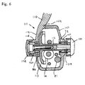
- the handle shaft is supported by the frame assembly exclusively, or by the frame assembly and the cover together. As shown in Figs. 7 and 8, the shaft can also be supported by the cover exclusively.
- the reel body 202 of the spinning reel comprises a frame assembly 210 which supports the rotor 3 and the spool 4, and a cover 211 which detachably screws onto the frame assembly 210.
- the frame assembly 210 comprises, for example, a thin-walled aluminum alloy component.
- the interior 210a of the frame assembly 210 is equipped with a rotor drive mechanism 5 for rotating the rotor 3 and with a level wind mechanism 6 for winding up the fishing line evenly through forward and backward motion of the spool 4.
- the cover 211 is fabricated, for example, from titanium, and preferably is manufactured by a lost wax process.
- the cover 211 comprises a thin-walled cover member 211a that covers the opening 210a of the frame assembly 210, and a mounting leg member 211 b that projects upward from the cover member 211 a.
- the cover member 211a is provided with a handle support 207 which rotatably supports the handle 201.
- the mounting leg member 211b preferably is a thick solid component.
- a rod mounting member 211c that projects in both directions longitudinally is disposed at its distal end.
- the rotor drive mechanism 5 comprises a handle shaft 212 to which the handle 201 is linked, an integrally formed master gear 213 which is located at the distal end of the handle shaft 212, and a pinion gear 14 which meshes with the master gear 213.
- the handle shaft 212 is rotatably supported by the handle support 207.
- the handle support 207 comprises a support sleeve 208 provided to the cover member 211a, and two bearings 9, disposed within the support sleeve 208 at intervals in the axial direction of the handle shaft 212, for rotatably supporting the handle shaft 212.
- the support sleeve 208 extends outward from the cover member 211 a in a direction perpendicular to the spool shaft 20.
- the mounting leg member 211b and the handle support 207 components of which high strength is required, preferably are integrated, thereby allowing the rest of the frame assembly 210 to be made lighter and thinner, affording higher precision. Since a relatively high strength metal material is preferably used for the cover 211, the need to increase the thickness of the mounting leg member 211b and cover member 211a is obviated, preventing the reel from becoming bulky.
- inventive spinning reel is not limited to the foregoing embodiments, and the present invention has potential application in designs equipped with a drag mechanism, or those equipped with a braking mechanism which incorporates a brake lever, rather than an anti-reverse mechanism.
- mounting leg cover member, and other components is not limited to those described in the context of the foregoing embodiment.
- the frame assembly and the mounting leg member are constituted as separate members. Since the presence of both thin areas and thick areas in a single component is eliminated, the thick areas remain unaffected during molding, even when the wall thickness of the frame assembly is reduced. Thus, the precision of the frame assembly can be maintained at a high level by reducing the thickness of the frame assembly.
- the cover member is a simple cover for covering the frame assembly, and as such does not require particularly high precision.
- the mounting leg member can be made thick in order to maintain high strength on the part of the mounting leg member. Since the mounting leg member is integrated with the cover, a structure that is simpler than that entailing separate members can be adopted while still maintaining strength.
Landscapes
- Life Sciences & Earth Sciences (AREA)
- Environmental Sciences (AREA)
- Animal Husbandry (AREA)
- Biodiversity & Conservation Biology (AREA)
- Spinning Or Twisting Of Yarns (AREA)
Applications Claiming Priority (6)
| Application Number | Priority Date | Filing Date | Title |
|---|---|---|---|
| JP103032/96 | 1996-04-25 | ||
| JP10303296 | 1996-04-25 | ||
| JP10303296 | 1996-04-25 | ||
| JP02928697A JP3372809B2 (ja) | 1996-04-25 | 1997-02-13 | スピニングリールのフレーム構造 |
| JP2928697 | 1997-02-13 | ||
| JP29286/97 | 1997-02-13 |
Publications (3)
| Publication Number | Publication Date |
|---|---|
| EP0803191A2 EP0803191A2 (en) | 1997-10-29 |
| EP0803191A3 EP0803191A3 (en) | 1998-08-19 |
| EP0803191B1 true EP0803191B1 (en) | 2005-01-26 |
Family
ID=26367461
Family Applications (1)
| Application Number | Title | Priority Date | Filing Date |
|---|---|---|---|
| EP97302710A Expired - Lifetime EP0803191B1 (en) | 1996-04-25 | 1997-04-21 | Frame structure for spinning reel |
Country Status (8)
| Country | Link |
|---|---|
| US (1) | US5788173A (zh) |
| EP (1) | EP0803191B1 (zh) |
| JP (1) | JP3372809B2 (zh) |
| KR (1) | KR100433369B1 (zh) |
| CN (1) | CN100364391C (zh) |
| DE (1) | DE69732316T2 (zh) |
| MY (1) | MY116897A (zh) |
| TW (1) | TW323218B (zh) |
Families Citing this family (15)
| Publication number | Priority date | Publication date | Assignee | Title |
|---|---|---|---|---|
| JP3556058B2 (ja) * | 1996-10-30 | 2004-08-18 | 株式会社シマノ | スピニングリールのスプール軸往復動機構 |
| JP4445094B2 (ja) * | 1999-10-27 | 2010-04-07 | 株式会社シマノ | スピニングリールのロータ |
| JP2003079291A (ja) * | 2001-09-12 | 2003-03-18 | Shimano Inc | スピニングリールの往復移動機構 |
| JP2003225039A (ja) * | 2002-02-05 | 2003-08-12 | Shimano Inc | スピニングリールのリール本体 |
| US7118059B2 (en) | 2003-01-29 | 2006-10-10 | Shimano Inc. | Reel unit for spinning reel |
| JP4022480B2 (ja) * | 2003-01-29 | 2007-12-19 | 株式会社シマノ | スピニングリールのリール本体 |
| US7028937B2 (en) * | 2003-02-05 | 2006-04-18 | Shimano Inc. | Reel unit for spinning reel |
| JP2004236568A (ja) * | 2003-02-05 | 2004-08-26 | Shimano Inc | スピニングリールのリール本体 |
| JP4804279B2 (ja) * | 2006-08-31 | 2011-11-02 | 株式会社シマノ | スピニングリール |
| US7275705B1 (en) | 2006-09-07 | 2007-10-02 | Shakespeare Company, Llc | Spinning reel having two-piece frame and leg assembly with concealable attachment points |
| WO2012112560A1 (en) | 2011-02-14 | 2012-08-23 | Arribe Manufacturing, Llc | Fishing reel |
| JP6166558B2 (ja) * | 2013-03-13 | 2017-07-19 | 株式会社シマノ | 両軸受リール |
| JP6419020B2 (ja) * | 2015-04-28 | 2018-11-07 | グローブライド株式会社 | 魚釣用スピニングリール |
| JP6871141B2 (ja) * | 2017-12-12 | 2021-05-12 | グローブライド株式会社 | 魚釣用スピニングリール |
| JP7113707B2 (ja) * | 2018-09-14 | 2022-08-05 | 株式会社シマノ | スピニングリール |
Family Cites Families (12)
| Publication number | Priority date | Publication date | Assignee | Title |
|---|---|---|---|---|
| GB361601A (en) * | 1930-11-15 | 1931-11-26 | Light Casting Reel Company Ltd | Improvements in and relating to casting reels for angling |
| US3788570A (en) * | 1970-12-12 | 1974-01-29 | Ryobi Ltd | Spinning reel for fishing |
| JPS591509Y2 (ja) * | 1979-03-17 | 1984-01-17 | ダイワ精工株式会社 | 釣用リ−ルのボデイカバ−止め構造 |
| JPS57166925A (en) * | 1981-04-03 | 1982-10-14 | Daiwa Seiko Co | Production of enclosure of spinning reel |
| JPS5883267U (ja) * | 1981-11-30 | 1983-06-06 | ダイワ精工株式会社 | 魚釣用スピニングリ−ル |
| JPS6083519A (ja) * | 1983-10-13 | 1985-05-11 | 株式会社シマノ | 釣用リ−ル |
| JPH0618459Y2 (ja) * | 1986-07-21 | 1994-05-18 | リョービ株式会社 | スピニングリール |
| KR930001505Y1 (ko) * | 1991-06-08 | 1993-03-30 | 주식회사은성사 | 낚시용 스피닝릴의 방수장치 |
| GB2261354B (en) * | 1991-10-15 | 1995-01-18 | Shimano Kk | Spinning reel |
| JP2561243Y2 (ja) * | 1992-03-06 | 1998-01-28 | 株式会社シマノ | スピニングリール |
| JPH065465U (ja) * | 1992-06-29 | 1994-01-25 | 株式会社シマノ | スピニングリール |
| US5443571A (en) * | 1992-07-15 | 1995-08-22 | Zebco Corporation | Wrap around side cover for a spinning fishing reel |
-
1997
- 1997-02-13 JP JP02928697A patent/JP3372809B2/ja not_active Expired - Fee Related
- 1997-02-24 TW TW086102210A patent/TW323218B/zh not_active IP Right Cessation
- 1997-03-06 KR KR1019970007418A patent/KR100433369B1/ko not_active IP Right Cessation
- 1997-03-17 US US08/818,926 patent/US5788173A/en not_active Expired - Lifetime
- 1997-04-21 EP EP97302710A patent/EP0803191B1/en not_active Expired - Lifetime
- 1997-04-21 DE DE69732316T patent/DE69732316T2/de not_active Expired - Lifetime
- 1997-04-24 MY MYPI97001806A patent/MY116897A/en unknown
- 1997-04-25 CN CNB971137420A patent/CN100364391C/zh not_active Expired - Lifetime
Also Published As
| Publication number | Publication date |
|---|---|
| US5788173A (en) | 1998-08-04 |
| JP3372809B2 (ja) | 2003-02-04 |
| TW323218B (zh) | 1997-12-21 |
| JPH104836A (ja) | 1998-01-13 |
| DE69732316T2 (de) | 2006-01-12 |
| KR19980069705A (ko) | 1998-10-26 |
| DE69732316D1 (de) | 2005-03-03 |
| EP0803191A2 (en) | 1997-10-29 |
| CN1173277A (zh) | 1998-02-18 |
| EP0803191A3 (en) | 1998-08-19 |
| KR100433369B1 (ko) | 2004-08-30 |
| CN100364391C (zh) | 2008-01-30 |
| MY116897A (en) | 2004-04-30 |
Similar Documents
| Publication | Publication Date | Title |
|---|---|---|
| EP0803191B1 (en) | Frame structure for spinning reel | |
| JP4804279B2 (ja) | スピニングリール | |
| US7121491B2 (en) | Reel unit for spinning reel | |
| JP2003225039A (ja) | スピニングリールのリール本体 | |
| EP0839445B1 (en) | Spinning reel having a narrow reel body housing | |
| EP0811320B1 (en) | Spinning reel | |
| JP3339522B2 (ja) | スピニングリール | |
| KR100942709B1 (ko) | 스피닝 릴의 로터 | |
| EP0806137B1 (en) | Spinning reel | |
| KR101058363B1 (ko) | 스피닝 릴의 마스터 기어 | |
| JP3892697B2 (ja) | スピニングリールの釣り糸案内機構 | |
| EP1407662B1 (en) | Fishing line guide mechanism for spinning reel | |
| KR20040071073A (ko) | 스피닝 릴의 릴 본체 | |
| JPH08131027A (ja) | スピニングリール | |
| JP4022480B2 (ja) | スピニングリールのリール本体 | |
| JP2000060374A (ja) | スピニングリールの釣り糸案内機構 | |
| JP7391062B2 (ja) | 魚釣用スピニングリール | |
| JP7384851B2 (ja) | 魚釣用スピニングリール | |
| JP2000023600A (ja) | 釣り用リールのレベルワインド機構 | |
| JP4141275B2 (ja) | スピニングリールのリール本体 | |
| JPH11169036A (ja) | 釣り用リール | |
| JP4128303B2 (ja) | スピニングリールのスプール及び糸巻補助具 | |
| JPH11196720A (ja) | スピニングリール | |
| JP2000217473A (ja) | スピニングリールのスプール | |
| JP2003174838A (ja) | スピニングリールのスプール |
Legal Events
| Date | Code | Title | Description |
|---|---|---|---|
| PUAI | Public reference made under article 153(3) epc to a published international application that has entered the european phase |
Free format text: ORIGINAL CODE: 0009012 |
|
| AK | Designated contracting states |
Kind code of ref document: A2 Designated state(s): DE DK FR GB IT SE |
|
| PUAL | Search report despatched |
Free format text: ORIGINAL CODE: 0009013 |
|
| AK | Designated contracting states |
Kind code of ref document: A3 Designated state(s): DE DK FR GB IT SE |
|
| 17P | Request for examination filed |
Effective date: 19990413 |
|
| 17Q | First examination report despatched |
Effective date: 20001106 |
|
| GRAP | Despatch of communication of intention to grant a patent |
Free format text: ORIGINAL CODE: EPIDOSNIGR1 |
|
| GRAS | Grant fee paid |
Free format text: ORIGINAL CODE: EPIDOSNIGR3 |
|
| GRAA | (expected) grant |
Free format text: ORIGINAL CODE: 0009210 |
|
| AK | Designated contracting states |
Kind code of ref document: B1 Designated state(s): DE DK FR GB IT SE |
|
| REG | Reference to a national code |
Ref country code: GB Ref legal event code: FG4D |
|
| REF | Corresponds to: |
Ref document number: 69732316 Country of ref document: DE Date of ref document: 20050303 Kind code of ref document: P |
|
| PG25 | Lapsed in a contracting state [announced via postgrant information from national office to epo] |
Ref country code: SE Free format text: LAPSE BECAUSE OF FAILURE TO SUBMIT A TRANSLATION OF THE DESCRIPTION OR TO PAY THE FEE WITHIN THE PRESCRIBED TIME-LIMIT Effective date: 20050426 Ref country code: DK Free format text: LAPSE BECAUSE OF FAILURE TO SUBMIT A TRANSLATION OF THE DESCRIPTION OR TO PAY THE FEE WITHIN THE PRESCRIBED TIME-LIMIT Effective date: 20050426 |
|
| PLBE | No opposition filed within time limit |
Free format text: ORIGINAL CODE: 0009261 |
|
| STAA | Information on the status of an ep patent application or granted ep patent |
Free format text: STATUS: NO OPPOSITION FILED WITHIN TIME LIMIT |
|
| 26N | No opposition filed |
Effective date: 20051027 |
|
| ET | Fr: translation filed | ||
| PGFP | Annual fee paid to national office [announced via postgrant information from national office to epo] |
Ref country code: IT Payment date: 20100421 Year of fee payment: 14 |
|
| PG25 | Lapsed in a contracting state [announced via postgrant information from national office to epo] |
Ref country code: IT Free format text: LAPSE BECAUSE OF NON-PAYMENT OF DUE FEES Effective date: 20110421 |
|
| REG | Reference to a national code |
Ref country code: FR Ref legal event code: PLFP Year of fee payment: 20 |
|
| PGFP | Annual fee paid to national office [announced via postgrant information from national office to epo] |
Ref country code: FR Payment date: 20160309 Year of fee payment: 20 |
|
| PGFP | Annual fee paid to national office [announced via postgrant information from national office to epo] |
Ref country code: DE Payment date: 20160412 Year of fee payment: 20 Ref country code: GB Payment date: 20160420 Year of fee payment: 20 |
|
| REG | Reference to a national code |
Ref country code: DE Ref legal event code: R071 Ref document number: 69732316 Country of ref document: DE |
|
| REG | Reference to a national code |
Ref country code: GB Ref legal event code: PE20 Expiry date: 20170420 |
|
| PG25 | Lapsed in a contracting state [announced via postgrant information from national office to epo] |
Ref country code: GB Free format text: LAPSE BECAUSE OF EXPIRATION OF PROTECTION Effective date: 20170420 |