EP0802995B1 - Procede de rentrage de peignes pour metiers a tisser et dispositif correspondant - Google Patents
Procede de rentrage de peignes pour metiers a tisser et dispositif correspondant Download PDFInfo
- Publication number
- EP0802995B1 EP0802995B1 EP96935464A EP96935464A EP0802995B1 EP 0802995 B1 EP0802995 B1 EP 0802995B1 EP 96935464 A EP96935464 A EP 96935464A EP 96935464 A EP96935464 A EP 96935464A EP 0802995 B1 EP0802995 B1 EP 0802995B1
- Authority
- EP
- European Patent Office
- Prior art keywords
- gap
- reed
- warp thread
- threader
- dents
- Prior art date
- Legal status (The legal status is an assumption and is not a legal conclusion. Google has not performed a legal analysis and makes no representation as to the accuracy of the status listed.)
- Expired - Lifetime
Links
- 235000014676 Phragmites communis Nutrition 0.000 title claims description 113
- 238000000034 method Methods 0.000 title claims description 9
- 238000009499 grossing Methods 0.000 claims description 3
- 230000001678 irradiating effect Effects 0.000 claims description 3
- 230000005622 photoelectricity Effects 0.000 claims description 3
- 230000033001 locomotion Effects 0.000 description 19
- 230000007246 mechanism Effects 0.000 description 18
- 239000004744 fabric Substances 0.000 description 4
- 230000004044 response Effects 0.000 description 3
- 230000008859 change Effects 0.000 description 2
- 238000004519 manufacturing process Methods 0.000 description 2
- 238000012986 modification Methods 0.000 description 2
- 230000004048 modification Effects 0.000 description 2
- 235000004522 Pentaglottis sempervirens Nutrition 0.000 description 1
- 240000004050 Pentaglottis sempervirens Species 0.000 description 1
- 206010044565 Tremor Diseases 0.000 description 1
- 238000013459 approach Methods 0.000 description 1
- 238000006243 chemical reaction Methods 0.000 description 1
- 238000005520 cutting process Methods 0.000 description 1
- 238000010586 diagram Methods 0.000 description 1
- 238000002474 experimental method Methods 0.000 description 1
- 239000012530 fluid Substances 0.000 description 1
- 238000012545 processing Methods 0.000 description 1
- 230000007480 spreading Effects 0.000 description 1
- 238000003892 spreading Methods 0.000 description 1
- 238000012546 transfer Methods 0.000 description 1
Images


Classifications
-
- D—TEXTILES; PAPER
- D03—WEAVING
- D03J—AUXILIARY WEAVING APPARATUS; WEAVERS' TOOLS; SHUTTLES
- D03J1/00—Auxiliary apparatus combined with or associated with looms
- D03J1/14—Apparatus for threading warp stop-motion droppers, healds, or reeds
Definitions
- the present invention relates to a method of drawing a warp thread in a reed of a loom and a reed drawing-in apparatus used in the same method, in more detail, it relates to said method and apparatus wherein not only a warp thread can be properly and smoothly drawn into a respective gap between adjacent dents even of a reed where the dents are laid with extremely high density without being cut off during the reed drawing-in operation, but also a threader for hooking a warp thread and drawing it into the reed can be used for a longer time. It is a state-of-the-art invention serving to streamline a reed drawing-in job especially for the production of high-density fabrics.
- the present applicant has proposed a high-precision reed drawing-in apparatus in Japanese Patent Publication No.8-16301 comprising a search light source irradiating search light onto a reed and a CCD camera picturing the reed surface irradiated with the search light and a microcomputer for calculating the distance to a target gap between adjacent dents on the basis of a picture signal output from said CCD camera and then for outputting a numerical movement command signal in proportion to the calculated distance, and a threader having a hook part which is formed thinner than the gap between adjacent dents of the reed, wherein the hook part is thrust into the gap so as to hook a warp thread and draw it into said gap, and a work carrier carrying said search light source, CCD camera, microcomputer and threader which sequentially moves from one gap to another on the reed in accordance with said numerical movement command signal so as to draw a warp thread into a target gap with the hook part of the threader.
- the present invention is to solve those problems and to provide both a reed drawing-in method whereby a warp thread can be properly and smoothly drawn into a respective gap between adjacent dents of even an extremely high-density reed without being cut off during the reed drawing-in operation so that the operation is hardly suspended, and a high-precision apparatus used in the same method.
- Claim 3 describes an advantageous embodiment of the apparatus of claim 2.
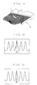
- Figure 1 is a schematic plan view of the reed drawing-in apparatus embodied in the present invention
- Figure 2 is a schematic sectional view of the work carrier carrying a CCD camera, a beam source, a gap opener and a threader
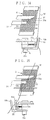
- Figure 3 is a fragmentary enlarged sectional view of the work carrier showing the motions of a gap opener and a threader embodied in the present invention
- Figure 4 is an enlarged perspective view of a warp thread suction tensioner excluding the beam source of Figure 1
- Figure 5 is a fragmentary enlarged view of a warp thread selector of the work carrier showing said selector hooking a warp thread sorted out from a warp thread holder and drawing said thread toward the delivery position
- Figure 6 is a fragmentary enlarged view of a warp thread cutter and a warp thread manipulator of the work carrier showing said cutter cutting off a warp thread and said manipulator picking up said cut-off thread
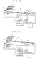
- Figure 7 is a block diagram showing the three-way control signal flow between a
- the method adopted in the present invention is characterized in that a warp thread, held in a thread supply section arranged opposite to the reed of a loom, is sequentially drawn into a respective gap by means of the association between a "Gap Opening Operation” where the dents disposed on both sides of the respective gap are temporarily and sequentially enlarged by intermittently stopping a work carrier provided with a gap opener and a threader while the work carrier is moving in the latitudinal direction of the reed, and a "Threader Inserting Operation" where the threader is thrust into the enlarged gap.
- the apparatus adopted in the present invention is characterized in that the associated movement between a gap opener which temporarily spreads apart the dents disposed on both sides of a target gap just located where a work carrier has stopped, and a threader which is thrust into the gap enlarged by the gap opener and hooks a warp thread from the thread supply section and draws said warp thread into the enlarged gap, is incorporated into the work carrier which sequentially stops in response to the respective gap while moving in the latitudinal direction of the reed.
- a work carrier movement is adopted in the present invention for sequentially spreading apart the dents disposed on both sides of a respective gap.
- This work carrier is under the numerical control of an input movement command signal and sequentially and precisely stops in response to the respective gap while moving in the latitudinal direction of the reed.
- the precise shift of the work carrier across the reed is realized by means of a light beam source, a CCD camera and a microcomputer carried on the carrier. Namely, when the light beam projects a localised search beam towards the surface of the reed where a number of dents are disposed, a CCD camera converts the quantity of light received, which varies according to whether there is a dent at a searched area, into photoelectricity and outputs said light quantity as a picture signal to a microcomputer.
- a microcomputer calculates the distance to a target gap existing between adjacent dents on the basis of said picture signal output from said CCD camera and then outputs a numerical movement command signal so as to numerically control a shift motor installed in the work carrier and shift said work carrier to a computed position.
- the gap opener and the threader are also carried on the work carrier of the present invention.
- the gap opener is a mechanical part which is thrust into a respective target gap between adjacent dents of the reed just opposite where the work carrier has stopped under the numerical control of the input movement command signal as mentioned above and temporarily enlarges the gap.
- a sharp-pointed or lanceolate pin by means of a back-and-forth driving mechanism (e.g. a servomotor and cam mechanism) can be adopted.
- a back-and-forth driving mechanism e.g. a servomotor and cam mechanism
- the threader it is thrust into the enlarged gap and hooks a warp thread from the thread supply section arranged opposite the reed with a hook part provided at its tip end so as to draw said warp thread into the reed.
- the threader moves in association with and subsequently to the gap opener also by means of a back-and-forth driving mechanism such as a servomotor. Therefore, the hook part is longitudinally arranged on the threader along a gap formed by the reed-dents.
- a back-and-forth driving mechanism such as a servomotor. Therefore, the hook part is longitudinally arranged on the threader along a gap formed by the reed-dents.
- the computer receiving the information that the work carrier has stopped successively sends a thrust signal and a reed drawing-in signal to the driving mechanism of the gap opener and the threader respectively.
- a high-density reed (400 dents/inch) (R) is horizontally placed on the apparatus (D).
- a reversely rotatable ball screw (B) driven by a shift control motor (servomotor) (M) is horizontally suspended below said reed (R).
- Said ball screw (B) engages with a work carrier (WC) so as to make said carrier shift just by a required distance.
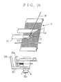
- a warp thread suction tensioner (31) as shown in Figure 4 and a warp thread manipulator (32), a warp thread cutter (33), a warp thread transport hook (34) and a warp thread selector (35) respectively as shown in Figures 5 and 6, and a warp thread arrangement mechanism (40) as shown in Figures 17 and 18, are all systematically carried on the work carrier (WC) along the transfer passage of the warp thread.
- said beam source (11) and warp thread suction tensioner (31) are placed above the reed (R) arranged on the reed drawing-in apparatus (D) while said CCD camera (12) and threader (23) are opposedly placed below the reed (R) against the beam source (11).
- Said beam source (11), warp thread suction tensioner (31), CCD camera (12) and threader (23) are all arranged so that they shift together with the work carrier (WC).
- a gap between adjacent dents of the high-density reed (R) searched by the beam source (11) is imaged in the CCD camera (12) and the imaged gap is analyzed with a microcomputer (C) installed on the work carrier (WC). Then, the analysis data is sent to the servomotor (M) as shown in Figure 7 so that the work carrier (WC) shifts accordingly and reaches a gap between adjacent dents where the search light intensity becomes largest directly below the gap.
- said computer (C) emits a thrust signal to the servomotor (22) of the gap opener (21) so as to actuate upward projection of a sharp-pointed pin (21a)(a gap opener tip) through the target gap.
- the projection of the sharp-pointed pin (21a) causes the dents on both sides of the gap to separate so that the gap becomes enlarged.
- said computer (C) emits a threading signal to the servomotor (24) of the threader (23).
- the actuation of the threader (23) causes its hook part (2f) to be thrust into the gap and to project a little above the reed (R) (see Figures 10 and 11).
- a warp thread (W) is led into the upper side of the reed (R) and the end portion of the thread (W) is drawn into the warp thread suction tensioner (31).
- This warp thread suction tensioner (31) takes into the warp thread (W) through its suction opening (31a) under a required air suction pressure in engagement with a compressor (not shown in the drawings).
- the warp thread (W) taken into the tensioner (31) is arranged so that it meets the hook part (2f) projecting above the reed (R).
- a infrared LED (light emitting diode) of super-high luminance is adopted as the beam source (11) provided above the reed (R) arranged on the reed drawing-in apparatus (D) embodied in the present invention.
- This LED is upwardly rotatably and escapably installed on a bracket (H) hinged with the work carrier (WC).
- the LED along with a warp thread suction tensioner (31) are sprung up so that they escape to a position where they do not interfere with the reed (R).
- the CCD camera (12) arranged below the reed (R) is for the purpose of linear image processing wherein charge coupled elements are arranged in one line parallel with the latitudinal direction of the reed-dents (4096 picture elements:2 ⁇ /picture element).
- This camera (12) excites photoelectrical conversion according to the intensity of search light passing the interval between adjacent dents of the reed (R) so as to output a picture signal.
- the picture signal output by this camera (12) is sent to the microcomputer (C) for smoothing as shown in Figures 12 and 13.
- an address (1900) where the quantity of light received has peaked is read as a target gap.
- the computer (C) is preliminarily programmed so that it can read the current position of the sharp-pointed pin (21a) of the gap opener (21) and that of the hook part (2f) of the threader (23). Therefore, the computer (C) automatically emits a movement command signal to the work carrier (WC) so as to shift the sharp-pointed pin (21a) and the hook part right below an adjacent gap on the right-hand side of the previously threaded gap.
- the shift of the sharp-pointed pin (21a) and the hook part (2f) to the latitudinal direction of the reed-dents or the shift thereof to the subsequent gap accompanies that of the work carrier (WC).
- the carrier (WC) shifts by rotation of the ball screw provided at the lower portion of the reed drawing-in apparatus (D).
- rotating a servomotor (M) engaged with the ball screw (B) by a fixed rate see a control mechanism chart in Figure 7) enables the sharp-pointed pin (21a) and the hook part (2f) to accurately shift to the target gap.
- the microcomputer (C) emits a thrust signal to a servomotor (22) of the gap opener (21) so as to cause the sharp-pointed pin (a gap opener tip)(21a) to project above the reed (R). Because the tip of the pin (21a) is aimed at the target gap, it is properly thrust into the intermediate position between adjacent dents without colliding with the dents and enlarges the gap.
- said microcomputer (C) sends a threading signal to the servomotor (24) of the threader (23) so as to actuate said servomotor (24).
- the hook part (2f) smoothly projects through the gap and extends upwardly a little above the reed (R) (see Figure 10).
- the sharp-pointed pin (21a) of the gap opener (21) provided with the reed drawing-in apparatus embodied in the present invention has a tapered tip, the diameter of which at the foot is 2mm and the length of which along the sloping side is 7mm.
- the hook part (2f) of the threader (23) adopted in the reed drawing-in apparatus embodied in the present invention has a tip portion, the thinnest part of which is 3 ⁇ and the thickest part of which is only 70 ⁇ and the gap is enlarged by 2mm with the sharp-pointed pin (21a) as mentioned above, and also because the hook part (2f) is accurately carried and positioned just below an intermediate position between adjacent dents, it can be smoothly and spaciously drawn into a reed even with 400 dents/inch.
- one warp thread (W) is selected from a number of the files of warp threads (W ⁇ W ⁇ ⁇ ⁇ ⁇ ) orderly arranged in a warp thread holder (51) of the reed drawing-in apparatus (D) by means of the shedding motion of a pair of leasing strings that are not shown in the drawings.
- the warp thread selector (35) carried on the central part of the work carrier (WC) catches this selected warp thread (W) (see Figure 5). Namely, a hook (35a) capable of catching only one warp thread (W) is formed on said warp thread selector (35). When the selected thread is hooked on the hook (35a), the hook (35a) swings towards the work carrier (WC) so as to draw the selected warp thread (W) near a fixed position.
- the warp thread transport hook (34) provided on the selector (35) starts moving.
- This hook (34) is a warp thread relay mechanism whereby the selected thread (W) hooked on the selector (35) is shifted to a position where the warp thread manipulator (32) can pick up the warp thread (W), and consists of a hook member horizontally moving to and fro as shown in Figures 5 and 6. In this way, the selected warp thread (W) transported by the warp thread transport hook (34) is delivered to the manipulator (32).
- the warp thread manipulator (32) has a pair of forks (32a) and (32b) between which the warp thread (W) transported from the selector (35) is put. Then, the warp thread (W) between said forks (32a) and (32b) is cut at a fixed location with scissor blades (3e) and (3e) of the warp thread cutter (33) (see Figure 6) and the manipulator (32) revolves around a support axis (32c) in the direction of the arrow indicated in Figure 14 with the warp thread (W) between the forks (32a) and (32b) so as to carry the warp thread (W) to the delivery position (see Figure 15).
- the warp thread (W) picked up and carried to the delivery position by the manipulator (32) with its forks (32a) and (32b), as shown in Figure 15, is taken into the warp thread suction tensioner (31) by air suction pressure so that it can be held stable while being hooked on the hook part (2f) of the threader (21).
- the manipulator (32) further proceeds to revolve around the support axis (32c) and returns to the original position. Then, the end portion of the warp thread (W) hooked on the hook part (2f) is further taken into the suction tensioner (31) so that it is held taut and straight.
- the suction opening (31a) of the warp thread suction tensioner (31) is formed flatly compressed in the direction of the hook part (2f) and also has a deep-cut slit (31b) formed in the direction of the forks (32a) and (32b) of the manipulator (32) which has arrived at the delivery position, even if the warp thread (W) is partly slack when the forks (32a) and (32b) have picked up and carried it, its end portion is taken in and pulled into the suction opening (31a) so that it is held taut and stable.
- the threading signal output by the microcomputer (C) switches the servomotor (24) of the threader (23) to the return mode.
- the warp thread (W) hooked on the hook part (2f) is still held sufficiently taut, it slips out of the suction opening (31a) against air suction pressure of the warp thread suction tensioner (31), is threaded through the gap and is discharged from the hook part (2f) below the reed (R).
- the servomotor (22) of the gap opener (21) is also switched to the return mode so that the sharp-pointed pin (21a) is retracted downwardly from the enlarged gap of the reed-dents.
- the reed-dents elastically recover.
- a warp thread arrangement mechanism (40) wherein a cut-off warp thread is orderly arranged, is provided below the reed (R) so that a warp thread drawn into the reed-dents gives no trouble either to the search for a target gap or to the operation of the gap opener (21) and the threader (23) respectively.
- this warp thread arrangement mechanism (40) is explained more in detail with reference to Figs. 17 and 18.
- a warp thread receiving bracket (42) for bundling warp threads (W) lowers according to the rotational angle of a cam (43). Then, a swing arm (41) moving horizontally to and fro by means of a boss (44a) of a crank plate (44) rotates above the bracket (42) and brushes aside a newly drawn-in warp thread (W) from the underside of the reed (R). The bracket (42) turns to rise so that it raises a bundle of warp threads including the warp thread (W) which has been newly drawn-in and put aside, and then the swing arm (41) returns to the original position passing under the bracket (42).
- the microcomputer (C) calculates the distance between the gap where the previously drawn-in warp thread (W) is and an adjacent or target gap to the right-hand side of said previously drawn-in gap so as to command the work carrier (WC) to shift to said target gap. In this way, sequentially drawing warp threads (W) into the reed-dents enables successive reed drawing-in operations.
- the warp thread holder (51) for orderly holding the files of warp threads (W ⁇ W ⁇ ⁇ ⁇ ) slides to and fro against the selector (35) by means of a rack and pinion which is not shown in the drawings.
- the selector (35) carried on the work carrier (WC) also slides towards the files of warp threads (W) arranged in the holder (51) during the reed drawing-in operation in response to the driving of the servomotor (M).
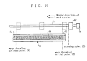
- the microcomputer (C) installed on the work carrier (WC) confirms by analyzing a picture signal output by the CCD camera that the work carrier (WC) is set on a predetermined starting point (0) of the ball screw (B) (step “a” of Figure 20). Then, the work carrier (WC) is shifted from the starting point (0) to a reed drawing-in initial point (S) of the reed (R) (step “b” of Figure 20).
- This initial point (S) is located at a gap in one of the two marginal regions between low-density areas (RL) formed at both sides of the reed (R) and a high-density area (RH) interposed between said low-density areas (RL) while the ultimate point (E) is located at a gap in the other marginal region.
- the microcomputer (C) installed on the work carrier (WC) analyzes and detects the position of the first gap and shifts the work carrier (WC) just below said gap under the numerical control and stops it (step “c" of Figure 20).
- the sharp-pointed pin (21a) of the gap opener (21) projects through the target gap where the work carrier (WC) has stopped, the dents disposed on both sides of the gap are separate so that said gap is enlarged (step “d” of Figure 20).
- the hook part (2f) of the threader (23) is thrust into the enlarged gap so that it projects a little above the reed (R) (step “e” of Figure 20).
- One warp thread (W) is selected from the files of warp threads (W ⁇ W ⁇ ⁇ ) (step “f” of Figure 20) and this selected thread is subject to air suction pressure while being hooked on the hook part (2f) of the threader (23) (step “g” of Figure 20). Thereafter, the warp thread (W) is drawn into the gap of the reed-dents by retracting the threader (23) below the reed (R) (step “h” of Figure 20).
- step "k” of Figure 20 After the sharp-pointed pin (21a) of the gap opener (21) has been retreated below the reed (R) (step “i” of Figure 20) and the warp thread (W) hooked on the hook part (2f) has been unhooked (step “j” of Figure 20), one cycle of reed drawing-in operation is completed (step “k” of Figure 20).
- the microcomputer (C) reads whether there is a gap left or not and if so, the same reed drawing-in operation as mentioned above is performed on an adjacent gap (see “N" route in step “k” of Figure 20).
- two servomotors (22) and (24) are adopted as back-and-forth driving control mechanism for the sharp-pointed pin (21a) of the gap opener (21) and the threader (23) respectively in the present embodiment, but it is also possible to drive them with just one servomotor by causing time lag between the movement of the sharp-pointed pin (21a) and that of the hook part (2f) of the threader (23). It is also possible to adopt a driving mechanism by means of fluid pressure such as an air cylinder instead of those two servomotors.
- the sharp-pointed or lanceolate pin (21a) which is thicker at the foot is adopted as a tip of the gap opener (21) in the present embodiment, but it is also possible to insert an oar-like slat into a gap of adjacent reed-dents and twist said slat in the gap so as to enlarge it.
- a skillful means is adopted on the basis of the association between a "Gap Opening Operation” where the gap opener temporarily enlarges a respective gap by separating reed-dents disposed on both sides of the gap and a "Threader Inserting Operation” where the threader is thrust into the enlarged gap. Therefore, even when the reed drawing-in operation is performed on a high-density reed having an extremely fine gap between adjacent reed-dents, there is no case where the warp thread is damaged or cut off due to excessive stress such as friction during said operation.
- the reed drawing-in apparatus embodied in the present invention can properly and automatically perform fast reed drawing-in operation even on a high-density reed with more than 400 dents/inch. Therefore, it serves more effectively than the prior art proposed in Japanese Patent Publication No.8-16301 to streamline preparatory work in the factory where a high-density fabric is manufactured, so that its industrial applicability is extremely high.
Landscapes
- Engineering & Computer Science (AREA)
- Textile Engineering (AREA)
- Auxiliary Weaving Apparatuses, Weavers' Tools, And Shuttles (AREA)
- Looms (AREA)
Claims (3)
- Procédé de rentrage d'un fil de chaíne (W) dans un interstice entre les dents adjacentes dans un peigne haute densité (R) d'un métier à tisser, comprenant les étapes ci-dessous:(a) irradiation locale de la surface du peigne (R) avec un faisceau de détection infrarouge;(b) conversion d'une quantité de lumière dudit faisceau de détection variable en fonction de la présence d'une dent au niveau de la surface irradiée en photoélectricité par l'intermédiaire d'une caméra à dispositif de couplage de charge (CCD) (12), pour obtenir un signal d'image de sortie ayant une forme d'onde;(c) lissage de la forme d'onde;(d) détermination de l'emplacement d'une crête de la forme d'onde lissée;(e) calcul de la distance par rapport à un interstice visé entre les dents adjacentes sur la base de l'emplacement de la crête par l'intermédiaire d'un micro-ordinateur (C) avant d'entrer un signal de commande de déplacement numérique dans un porte-ouvrage (WC), pouvant être déplacé dans la direction de la largeur du peigne (R), de sorte à déplacer avec précision ledit porte-ouvrage (WC) vers une position de rentrage du peigne, en fonction des besoins, ledit porte-ouvrage (WC) comportant un dispositif d'ouverture des interstices (21) avec une aiguille à pointe tranchante (21a) destinée à agrandir ledit interstice et comportant un enfile-aiguille (23) pour rentrer un fil de chaíne (W) dans l'interstice;(f) agrandissement temporaire dudit interstice visé par enfoncement de l'aiguille (21a) dans l'interstice en vue de séparer les dents agencées sur les côtés opposés de l'interstice; et(g) enfoncement de l'enfile-aiguille (23) dans l'interstice agrandi et accrochage d'un fil de chaíne (W) provenant d'une section d'amenée des fils (31, 32), agencée en un point opposé au peigne (R), pour rentrer ainsi ledit fil de chaíne (W) dans l'interstice.
- Dispositif de rentrage de peigne pour un peigne haute densité (R) d'un métier à tisser, comprenant un porte-ouvrage (WC), pouvant se déplacer dans la direction de la largeur du peigne (R) vers une position de rentrage du peigne, selon les besoins, en présence d'un signal de commande de déplacement numérique, ledit porte-ouvrage (WC) comportant:(a) une source de faisceau (11) pour irradier localement la surface du peigne (R) avec un faisceau;(b) une caméra à dispositif de couplage de charge (12) destinée à convertir une quantité de lumière dudit faisceau variable en fonction de la présence d'une dent au niveau de la surface irradiée en photoélectricité, pour obtenir un signal d'image de sortie ayant une forme d'onde;(c) un micro-ordinateur (C) destiné à calculer la distance par rapport à un interstice visé entre les dents adjacentes sur la base d'un emplacement d'une crête déterminé à partir d'une forme d'onde dérivée dudit signal d'image de sortie, et pour émettre ledit signal de commande de déplacement numérique pour déplacer ledit porte-ouvrage (WC) vers la position de rentrage du peigne;(d) un enfile-aiguille (23) destiné à s'enfoncer dans l'interstice temporairement agrandi pour accrocher un fil de chaíne provenant d'une section d'amenée des fils (31, 32) agencée en un point opposé au peigne (R), et pour rentrer le fil de chaíne (W) dans l'interstice; caractérisé en ce que la source de faisceau est une source de faisceau infrarouge, la forme d'onde, sur la base de laquelle est déterminé l'emplacement de la crête étant lissée; et par(e) un dispositif d'ouverture des interstices (21) comportant une aiguille à pointe tranchante (21a) destinée à séparer les dents adjacentes sur les côtés opposés de l'interstice visé pour agrandir temporairement l'interstice lorsque le porte-ouvrage (WC) a atteint la position de rentrage du peigne.
- Dispositif de rentrage de peigne selon la revendication 2, dans lequel l'aiguille à pointe tranchante (21a) du dispositif d'ouverture (21) et l'enfile-aiguille (23) sont alignés dans la direction longitudinale de l'interstice entre les dents adjacentes.
Applications Claiming Priority (4)
| Application Number | Priority Date | Filing Date | Title |
|---|---|---|---|
| JP7292576A JPH09137342A (ja) | 1995-11-10 | 1995-11-10 | 経糸の筬通し方法、および同方法に用いる高精度筬通し機 |
| JP292576/95 | 1995-11-10 | ||
| JP29257695 | 1995-11-10 | ||
| PCT/JP1996/003142 WO1997017484A1 (fr) | 1995-11-10 | 1996-10-28 | Procede de rentrage de peignes pour metiers a tisser et dispositif correspondant |
Publications (2)
| Publication Number | Publication Date |
|---|---|
| EP0802995A1 EP0802995A1 (fr) | 1997-10-29 |
| EP0802995B1 true EP0802995B1 (fr) | 2000-01-19 |
Family
ID=17783567
Family Applications (1)
| Application Number | Title | Priority Date | Filing Date |
|---|---|---|---|
| EP96935464A Expired - Lifetime EP0802995B1 (fr) | 1995-11-10 | 1996-10-28 | Procede de rentrage de peignes pour metiers a tisser et dispositif correspondant |
Country Status (6)
| Country | Link |
|---|---|
| US (1) | US5806156A (fr) |
| EP (1) | EP0802995B1 (fr) |
| JP (1) | JPH09137342A (fr) |
| CN (1) | CN1175986A (fr) |
| DE (1) | DE69606279T2 (fr) |
| WO (1) | WO1997017484A1 (fr) |
Families Citing this family (9)
| Publication number | Priority date | Publication date | Assignee | Title |
|---|---|---|---|---|
| DE50111691D1 (de) * | 2000-06-20 | 2007-02-01 | Staeubli Ag Pfaeffikon | Vorrichtung und verfahren zur einführung von kettfäden in ein webblatt |
| JP4900306B2 (ja) * | 2008-04-03 | 2012-03-21 | 株式会社豊田自動織機 | ドローイングマシン |
| EP2199443B1 (fr) * | 2008-12-19 | 2016-03-16 | Stäubli AG Pfäffikon | Unité mobile pour le rentrage de la chaine |
| CN105350167B (zh) * | 2015-11-30 | 2017-01-25 | 浙江日发纺织机械股份有限公司 | 一种自动穿经机的经纱供给及切换机构 |
| DE202015008820U1 (de) * | 2015-12-28 | 2017-03-29 | Peter Beike | Kettfädeneinfädelvorrichtung |
| CN105755655B (zh) * | 2016-05-03 | 2017-11-03 | 佛山慈慧通达科技有限公司 | 一种全自动穿筘机 |
| CN105951282B (zh) * | 2016-06-29 | 2017-11-03 | 天津市纺织机械器材研究所 | 一种用于无限长编筘机的自动放料机构 |
| CN108315852B (zh) * | 2018-02-12 | 2019-07-23 | 首都师范大学 | 纺纱机穿线方法及装置 |
| CN111705400A (zh) * | 2020-06-30 | 2020-09-25 | 山东日发纺织机械有限公司 | 一种自动穿经机及筘刀插入钢筘的控制方法 |
Family Cites Families (11)
| Publication number | Priority date | Publication date | Assignee | Title |
|---|---|---|---|---|
| US1624928A (en) * | 1923-01-08 | 1927-04-19 | Barber Colman Co | Warp-drawing machine |
| US4215455A (en) * | 1979-04-02 | 1980-08-05 | Barber-Colman Company | Reed opener assembly |
| CH663040A5 (de) * | 1984-06-18 | 1987-11-13 | Bopp & Co Ag G | Maschine zum einziehen von kettfaeden in einen webkamm. |
| JPS6143460A (ja) * | 1984-08-07 | 1986-03-03 | Mitsubishi Electric Corp | 混成集積回路装置 |
| DE3638090C1 (de) * | 1986-11-07 | 1988-02-11 | Fischer Oskar Gmbh & Co | Vorrichtung zum Einziehen von Kettfaeden in ein Webblatt |
| US4894893A (en) * | 1987-06-11 | 1990-01-23 | C K D Kabushiki Kaisha | Pneumatic reed drawing-in apparatus |
| CH678196A5 (fr) * | 1988-05-27 | 1991-08-15 | Benninger Ag Maschf | |
| US5029374A (en) * | 1989-04-13 | 1991-07-09 | Hunter Associates Laboratory, Inc. | Loom reed drawing-in machine |
| JPH0424252A (ja) * | 1990-05-18 | 1992-01-28 | Nippon Filcon Co Ltd | 自動筬通し装置と自動筬通し方法 |
| JPH0816301B2 (ja) * | 1991-10-04 | 1996-02-21 | 合資会社橋詰研究所 | 高精度筬通し機 |
| JPH05311546A (ja) * | 1992-02-10 | 1993-11-22 | Nippon Filcon Co Ltd | 自動筬通し装置と自動筬通し方法 |
-
1995
- 1995-11-10 JP JP7292576A patent/JPH09137342A/ja active Pending
-
1996
- 1996-10-28 EP EP96935464A patent/EP0802995B1/fr not_active Expired - Lifetime
- 1996-10-28 CN CN96191403.3A patent/CN1175986A/zh active Pending
- 1996-10-28 DE DE69606279T patent/DE69606279T2/de not_active Expired - Fee Related
- 1996-10-28 US US08/836,584 patent/US5806156A/en not_active Expired - Fee Related
- 1996-10-28 WO PCT/JP1996/003142 patent/WO1997017484A1/fr not_active Ceased
Also Published As
| Publication number | Publication date |
|---|---|
| WO1997017484A1 (fr) | 1997-05-15 |
| DE69606279T2 (de) | 2000-08-03 |
| JPH09137342A (ja) | 1997-05-27 |
| CN1175986A (zh) | 1998-03-11 |
| EP0802995A1 (fr) | 1997-10-29 |
| US5806156A (en) | 1998-09-15 |
| DE69606279D1 (de) | 2000-02-24 |
Similar Documents
| Publication | Publication Date | Title |
|---|---|---|
| KR102209230B1 (ko) | 직기 모니터링 장치, 직기 및 모니터링 방법 | |
| EP0802995B1 (fr) | Procede de rentrage de peignes pour metiers a tisser et dispositif correspondant | |
| CN111498610B (zh) | 一种纱筒头纱尾纱捕获打结装置及方法 | |
| US7356893B2 (en) | Device for the separation of threads from a thread layer | |
| JPS59112053A (ja) | 欠陥のある横糸を縦糸開口から取出す装置を有するシヤトルなし織機 | |
| JP5774273B2 (ja) | 製織用たて糸群のたて糸を織機ハーネスの部材へ引き込むための引込機械および方法 | |
| US5165454A (en) | Detection of warp in reed dent before loom start up | |
| CA1333986C (fr) | Appareil de remplacement automatique de canette pour metier a tisser a navette | |
| EP1247886B1 (fr) | Dispositif et procédé d'entraînement d'un métier à tisser | |
| US4898213A (en) | Device for mending and trimming broken warp yarn | |
| EP0328680A1 (fr) | Appareil automatique a enfiler les fils de chaine | |
| GB2286601A (en) | Gripper axminster loom | |
| EP0449279B1 (fr) | Méthode pour localiser l'espacement entre des dents correspondant à un fil de chaîne cassé, et dispositif de localisation et de rentrage | |
| KR0184009B1 (ko) | 경사 통경기의 드롭 와이어 조종장치 | |
| JPS63288248A (ja) | 織機のひ道から欠陥よこ糸を除去する配置 | |
| EP0452932B1 (fr) | Méthode et dispositif de contrÔle pour la réparation des fils de chaîne | |
| KR930004078B1 (ko) | 수복(修腹)후의 경사의 처리방법 | |
| JP2844383B2 (ja) | たて糸補修装置 | |
| JPH0441747A (ja) | 切断たて糸の筬羽位置検出方法 | |
| NL8602827A (nl) | Werkwijze voor het losmaken van foutieve inslagdraden bij weefmachines en inrichting hierbij aangewend. | |
| JPH0816301B2 (ja) | 高精度筬通し機 | |
| JP2777741B2 (ja) | 筬羽位置検出方法 | |
| EP0508514A1 (fr) | Procédé et dispositif pour isoler un bout de fil d'un fil de chaîne cassé de la chaîne dans un métier à tisser |
Legal Events
| Date | Code | Title | Description |
|---|---|---|---|
| PUAI | Public reference made under article 153(3) epc to a published international application that has entered the european phase |
Free format text: ORIGINAL CODE: 0009012 |
|
| 17P | Request for examination filed |
Effective date: 19970726 |
|
| AK | Designated contracting states |
Kind code of ref document: A1 Designated state(s): CH DE LI |
|
| GRAG | Despatch of communication of intention to grant |
Free format text: ORIGINAL CODE: EPIDOS AGRA |
|
| 17Q | First examination report despatched |
Effective date: 19990224 |
|
| GRAG | Despatch of communication of intention to grant |
Free format text: ORIGINAL CODE: EPIDOS AGRA |
|
| GRAG | Despatch of communication of intention to grant |
Free format text: ORIGINAL CODE: EPIDOS AGRA |
|
| GRAH | Despatch of communication of intention to grant a patent |
Free format text: ORIGINAL CODE: EPIDOS IGRA |
|
| RBV | Designated contracting states (corrected) |
Designated state(s): CH DE LI |
|
| GRAH | Despatch of communication of intention to grant a patent |
Free format text: ORIGINAL CODE: EPIDOS IGRA |
|
| GRAA | (expected) grant |
Free format text: ORIGINAL CODE: 0009210 |
|
| AK | Designated contracting states |
Kind code of ref document: B1 Designated state(s): CH DE LI |
|
| REG | Reference to a national code |
Ref country code: CH Ref legal event code: NV Representative=s name: E. BLUM & CO. PATENTANWAELTE Ref country code: CH Ref legal event code: EP |
|
| REF | Corresponds to: |
Ref document number: 69606279 Country of ref document: DE Date of ref document: 20000224 |
|
| PLBE | No opposition filed within time limit |
Free format text: ORIGINAL CODE: 0009261 |
|
| STAA | Information on the status of an ep patent application or granted ep patent |
Free format text: STATUS: NO OPPOSITION FILED WITHIN TIME LIMIT |
|
| 26N | No opposition filed | ||
| PGFP | Annual fee paid to national office [announced via postgrant information from national office to epo] |
Ref country code: CH Payment date: 20031030 Year of fee payment: 8 |
|
| PGFP | Annual fee paid to national office [announced via postgrant information from national office to epo] |
Ref country code: DE Payment date: 20031103 Year of fee payment: 8 |
|
| PG25 | Lapsed in a contracting state [announced via postgrant information from national office to epo] |
Ref country code: LI Free format text: LAPSE BECAUSE OF NON-PAYMENT OF DUE FEES Effective date: 20041031 Ref country code: CH Free format text: LAPSE BECAUSE OF NON-PAYMENT OF DUE FEES Effective date: 20041031 |
|
| PG25 | Lapsed in a contracting state [announced via postgrant information from national office to epo] |
Ref country code: DE Free format text: LAPSE BECAUSE OF NON-PAYMENT OF DUE FEES Effective date: 20050503 |
|
| REG | Reference to a national code |
Ref country code: CH Ref legal event code: PL |