EP0802515B1 - Fahrzeugidentifikationssystem für ein elektrisches Mautgebühreneinzugssystem - Google Patents
Fahrzeugidentifikationssystem für ein elektrisches Mautgebühreneinzugssystem Download PDFInfo
- Publication number
- EP0802515B1 EP0802515B1 EP19970106105 EP97106105A EP0802515B1 EP 0802515 B1 EP0802515 B1 EP 0802515B1 EP 19970106105 EP19970106105 EP 19970106105 EP 97106105 A EP97106105 A EP 97106105A EP 0802515 B1 EP0802515 B1 EP 0802515B1
- Authority
- EP
- European Patent Office
- Prior art keywords
- vehicle
- radio wave
- antennas
- location
- directional
- Prior art date
- Legal status (The legal status is an assumption and is not a legal conclusion. Google has not performed a legal analysis and makes no representation as to the accuracy of the status listed.)
- Expired - Lifetime
Links
- 238000005305 interferometry Methods 0.000 claims description 25
- 238000001514 detection method Methods 0.000 claims description 10
- 230000000881 depressing effect Effects 0.000 claims 1
- 238000000034 method Methods 0.000 description 8
- 238000012545 processing Methods 0.000 description 7
- 238000005259 measurement Methods 0.000 description 6
- 238000004891 communication Methods 0.000 description 5
- 238000010586 diagram Methods 0.000 description 5
- 230000002411 adverse Effects 0.000 description 4
- 230000000903 blocking effect Effects 0.000 description 4
- 238000000691 measurement method Methods 0.000 description 4
- 230000002596 correlated effect Effects 0.000 description 2
- 230000000875 corresponding effect Effects 0.000 description 2
- 230000000694 effects Effects 0.000 description 2
- 208000001992 Autosomal Dominant Optic Atrophy Diseases 0.000 description 1
- 206010011906 Death Diseases 0.000 description 1
- 238000004458 analytical method Methods 0.000 description 1
- 238000013480 data collection Methods 0.000 description 1
- 230000004927 fusion Effects 0.000 description 1
- 238000009434 installation Methods 0.000 description 1
- 230000035945 sensitivity Effects 0.000 description 1
Images


Classifications
-
- G—PHYSICS
- G07—CHECKING-DEVICES
- G07B—TICKET-ISSUING APPARATUS; FARE-REGISTERING APPARATUS; FRANKING APPARATUS
- G07B15/00—Arrangements or apparatus for collecting fares, tolls or entrance fees at one or more control points
- G07B15/06—Arrangements for road pricing or congestion charging of vehicles or vehicle users, e.g. automatic toll systems
- G07B15/063—Arrangements for road pricing or congestion charging of vehicles or vehicle users, e.g. automatic toll systems using wireless information transmission between the vehicle and a fixed station
-
- G—PHYSICS
- G08—SIGNALLING
- G08G—TRAFFIC CONTROL SYSTEMS
- G08G1/00—Traffic control systems for road vehicles
- G08G1/01—Detecting movement of traffic to be counted or controlled
- G08G1/017—Detecting movement of traffic to be counted or controlled identifying vehicles
Definitions
- This invention relates to a vehicle identification system, and particularly relates to a vehicle identification system applicable to the electric toll collection (ETC) systems provided with a means for measuring the location of a vehicle by measuring direction of arrival (DOA) of a radio wave transmitted from the vehicle.
- ETC electric toll collection
- DOA direction of arrival
- a conventional vehicle identification system to be applied to ETC systems for use on toll roads is disclosed in US-A-5, 440, 109.
- an infrared beacon which is a component of an infrared communication system (IRK)
- an infrared video camera which is a component of an infrared location measurement system
- RD traffic radar system
- NV usual video camera
- FIR vehicle identification-recording system
- the system for identifying a vehicle which comes in a prescribed area in accordance with the present invention is provided with a receiving means for receiving a radio wave transmitted from the vehicle which comes in the prescribed area, an identification means for identifying the vehicle based on the ID signal included in said radio wave which is received by said receiving means, a directional finder for measuring the direction of arrival of the radio wave, and a location detection means for calculating the location of the vehicle based on the direction of arrival measured by the directional finder.
- the vehicle identification system in accordance with the present invention is provided with a means for measuring the direction of arrival of a radio wave transmitted from the vehicle which comes in the prescribed area by way of the two dimensional interferometry principle in terms of the directional angle and depression angle.
- a system for identifying the vehicle which comes in a toll collection area and for collecting a prescribed toll from the vehicle in accordance with this embodiment of the present invention is additionally provided with a vehicle tracking means for calculating the locus of the vehicle based on the identification information of the vehicle outputted from the identification means and the location information of the vehicle outputted from the location detection means, a camera means for taking a picture of the vehicle and outputting picture data, and a toll collection means for collecting a desired toll from the vehicle based on the locus data supplied from the vehicle tracking means and the picture data supplied from the camera means.
- the vehicle identification system of the embodiment identifies vehicles applying two-dimensional interferometry principle.
- a plurality of antennas 25 of a directional finder is deployed horizontally on a gantry 30, and the antennas 25 receive radio waves transmitted from vehicles.
- the antenna 25 is an array antenna comprising at least two antenna elements 50.
- directional lines 1 and 2 are drawn from the position of each antenna 25 based in the DOAs measured by way of the radio wave transmitted from a vehicle, and then the position of intersection of the two directional lines is determined as the location of the vehicle 10.
- a plurality of antenna elements 50 are used.
- the element numbers (natural numbers from 1 to n) are assigned to each antenna element 50.
- a signal outputted from each antenna element 50 is referred to as X1, X2, X3, ....,Xn wherein the numbers represent the element numbers respectively, and when antenna elements 50 are paired to form pairs, the phase difference ⁇ ij of each pair is represented by the following equation (1).
- the symbol i and j in the equation (1) represent the element numbers assigned to each antenna element 50.
- the theoretical value (or measured value) of signals received by each antenna element 50 is calculated (or measured) for all the directional angles ⁇ in the predetermined range, and the theoretical values (or measured values) are stored in a memory device.
- the theoretical values (or measured values) are represented as A1( ⁇ ), A2( ⁇ ), A3( ⁇ ), ..., An( ⁇ ) corresponding to the element numbers given to each antenna element 50.
- the phase difference of each antenna element 50 pair is represented by the following equation (2).
- the standard phase difference A ij ( ⁇ ) represented by the equation (2) is calculated previously for all the directional angles ⁇ .
- the directional angle ⁇ at which the phase difference ⁇ ij represented by the equation (1) becomes nearest the standard phase difference A ij ( ⁇ ) represented by the equation (2) is obtained, and the obtained directional angle is estimated to be the direction of arrival (DOA).
- DOA direction of arrival
- the least-square method is used for estimation of the DOA, and then the DOA ⁇ at which the following equation (3) becomes the minimum is determined.
- the DOA of the radio wave received by means of at least one pair of antennas 25 disposed horizontally on the gantry 30 as shown in Fig. 1 is determined by way of the above-mentioned one dimensional interferometry principle.
- Directional lines 1 and 2 are drawn from the position, where each antenna 25 is provided, based on the DOA of radio wave measured by means of each antenna 25 as shown in Fig. 3B.
- the intersection of the directional lines 1 and 2 drawn from each antenna 25 is detected as the location of the vehicle 10 which transmitted radio wave.
- the vehicle identification system by way of one dimensional interferometry principle tracks the locus of a vehicle by measuring one-dimensionally only the DOA of radio wave transmitted from the vehicle.
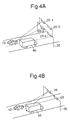
- a small vehicle 10 such as a passenger car moves side by side in parallel with a large vehicle 40 such as a trailer or a bus as shown in Fig. 4B
- radio wave from the vehicle 10 is blocked by the large vehicle 40 and does not arrive at the antenna 25 (this condition is referred to as shadowing). It is sometimes difficult to measure the location of a vehicle 10 in the case that the location is measured only by way of the DOA.
- a plurality of antennas 20 is deployed not only in horizontal direction but also in vertical direction as shown in Fig. 5.
- the directional angle and depression angle of arrival radio wave from the vehicle are measured two-dimensionally.
- the location of a vehicle is measured by way of two dimensional interferometry principle.
- At least two antennas 20 out of a plurality of antennas deployed in horizontal direction and vertical direction are selected as the antennas used for measurement of the directional angle and depression angle.
- the location of a vehicle in the vertical plane and horizontal plane is measured based on the information obtained from the selected antennas 20.
- An array antenna comprising at least three antenna elements 50 as shown in Fig. 6A is used as the antenna 20.
- the antenna 20 is installed with a depression angle of about 45 degrees toward the road to increase the radio wave sensitivity and range of measurement as shown in Fig. 6B.
- n antenna elements 50 to which the element numbers from 1 to n are given respectively are used.
- Signals outputted from each antenna element 50 are represented by X1, X2, X3, ..., Xn, wherein the numbers represent the element number respectively.
- Antenna elements 50 are paired to form pairs, and the phase difference ⁇ ij of each pair is represented by the above-mentioned equation (1).
- the theoretical value (or measured value) of a signal to be outputted from each antenna element 50 is determined previously for all the directional angle ⁇ and depression angle ⁇ , and these values are stored in a memory device.
- the theoretical value (or measured value) is represented by A1( ⁇ , ⁇ ), A2( ⁇ , ⁇ ), A3( ⁇ , ⁇ ), ..., An( ⁇ , ⁇ ) corresponding to the element number given to each antenna element 50.
- the standard phase A ij ( ⁇ , ⁇ ) represented by the equation (4) is determined previously for all the directional angle ⁇ and depression angle ⁇ .
- the directional angle ⁇ and depression angle ⁇ at which the phase difference ⁇ ij represented by the equation (1) becomes nearest the standard phase difference A ij ( ⁇ , ⁇ ) represented by the equation (4) is determined.
- the determined directional angle ⁇ and depression angle ⁇ are estimated to be a DOA of radio wave from a vehicle.
- the least square method is used for estimation of the DOA. That is, the DOA ⁇ and ⁇ at which the equation (5) becomes the minimum are determined.
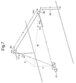
- the DOA ( ⁇ 1, ⁇ 1) and ( ⁇ 2 and ⁇ 2) of radio wave is determined.
- PA1 and PA2 are plane antennas
- ⁇ 1 and ⁇ 2 are directional angles of arriving radio wave
- ⁇ 1 and ⁇ 2 are depression angles of arriving radio wave
- b is a base line length namely a distance between PA1 and PA2
- d1 and d2 are horizontal distances from a vehicle 10 to each antenna 20
- h is a height from the vehicle 10 to the gantry 30
- H is the height of the gantry 30 to be installed.
- the installation height of the transceiver equipped with the vehicle from the ground is H-h.
- the location on the horizontal plane of the vehicle 10 which is transmitting radio wave is represented by coordinates X and Y having the origin at the location of the antenna 20 as shown in Fig. 8.
- the location X and Y of the vehicle 10 on the horizontal plane is determined by way of the following equations (6) to (10) using the measured DOA (directional angle and depression angle) of radio wave and the known base line length.
- d 1 bcos ⁇ 2 sin( ⁇ 1 + ⁇ 2 )
- d 2 bcos ⁇ 1 sin( ⁇ 1 + ⁇ 2 )
- At least two antennas which are estimated to be positioned at the place where the antennas can receive radio wave from the vehicle without blocking of radio wave by a large vehicle 40 are selected out of a plurality of antennas deployed.
- the locus of the DOA of radio wave measured for each antenna are traced, and most suitable antennas 20 are selected, that is, antennas deviated significantly from the average locus are not selected,
- antennas 20 are measured by way of two dimensional interferometry principle, it is possible to deploy antennas 20 not only in horizontal direction but also in vertical direction.
- the optimal combination of antennas 20 which receive radio wave without blocking by a large vehicle is selected, and thus the adverse effect of shadowing is suppressed.
- combinations of antennas such as antenna 20-1 and antenna 20-2, and antenna 20-1 and antenna 20-3 corresponds such optimal combination.
- the location of a vehicle is calculated both for the horizontal plane and vertical plane based on the directional angle and depression angle of arriving radio wave from the vehicle, the location of the vehicle is measured therefore more accurately.
- a vehicle 10 is provided with an IC card decoder 60 for analyzing an IC card on which information for identifying the vehicle is recorded and a transceiver 70 for transmitting an ID code signal analyzed by the decoder 60 by way of radio wave.
- the information such as the vehicle number, name of owner of the vehicle, and specified bank account number is recorded previously.
- the vehicle identification system at least four antennas 20 disposed in horizontal and vertical direction namely two dimensionally as shown in Fig. 4A, each antenna has at least three antenna elements 50 as shown in Fig. 6A, and receives the ID code signal transmitted from the vehicle 10.
- the plurality of antennas 20 receives radio wave (ID code signal) including the ID code transmitted from the transceiver 70 of the vehicle 10.
- the location of the vehicle 10 which transmitted radio wave is measured using the radio wave received by two antennas 20 which are selected by an antenna selector 100.
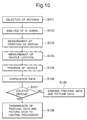
- the antenna selector 100 selects at least two antennas which are estimated to receive sufficiently radio wave from the vehicle without blocking of radio wave by a large vehicle as described hereinbefore. Alternately, the antenna selector 100 traces the locus of the DOA of radio wave measured by each antenna 20, rejects antennas with significant deviation from the average locus, and selects at least two optimal antennas 20 (S101).
- the radio wave namely ID code signal received by two antennas 20 selected by the antenna selector 100 is analyzed by a signal analyzer 110, and the vehicle 10 which transmitted the ID code signal is specified based on the analysis result of the signal analyzer 110 (S102).
- the directional angle ⁇ and depression angle ⁇ namely the DOA of the radio wave received by the antennas 20 are determined by a direction detector (directional finder) 120 (S103).
- the antenna selector 100 selects the antennas 20-1 and 20-2 shown in Fig. 5
- the directional angle and depression angle of the arriving radio wave received by the antennas 20-1 and 20-2 namely ( ⁇ 1, ⁇ 1) and ( ⁇ 2, ⁇ 2) shown in Fig. 7, are determined as the DOA by the direction detector 120.
- a location detector 130 calculates the location of the vehicle 10 both on the horizontal plane and vertical plane based on the DOA measured by the direction detector 120 (S104).
- the processing performed by the direction detector 120 and location detector 130 is operated by way of two dimensional interferometry principle.
- the size of the vehicle 10 may be estimated based on the height information of the vehicle 10 calculated by the location detector 130.
- a vehicle tracking unit 140 stores correspondingly a locus data of the vehicle 10 obtained by tracking the location data of the vehicle 10 obtained by the location detector 130 and the ID data for identifying the vehicle 10 obtained by the signal analyzer 110 in a memory device not shown in the figure.
- the movement of the vehicle 10 is tracked by the vehicle tracking unit 140 (S105).
- the tracking processing by the vehicle tracking unit 140 is realized by storing successively location data in the memory device while location data of the vehicle 10 obtained every certain time interval from the location detector 130 are correlated for each location change by way of correlation processing.
- a video camera 150 that is a picture data collection means takes a picture of the toll collection area, and the picture data which includes the picture of the vehicle 10 which is coming in the area is collected.
- a data correlating unit 160 correlates the locus data of the vehicle 10 supplied from the vehicle tracking unit 140 with the picture data supplied from the video camera 150 (S106).
- the vehicle number that is the information for specifying the vehicle 10 included in the locus data is correlated with the vehicle number obtained from the picture taken by the video camera 150. The identification whether the vehicle 10 which had the IC card and transmitted the ID code signal is exactly the same as the vehicle 10 on the picture taken by the video camera 150 is judged.
- the data correlation unit 160 supplies the correlation result and locus data including the ID for specifying the vehicle 10 to a controller 170.
- the controller 170 collects automatically a prescribed toll from the vehicle 10 which comes in the toll collection area based on the data supplied from the data correlation unit 160.
- the toll is collected by automatic withdrawing of the prescribed amount for the toll from the specified bank account registered in the IC card.
- the controller 170 judges whether the vehicle 10 is a violator vehicle based on the locus data supplied from the data correlation unit 160 (S107). If the data correlation unit 160 finds an incomplete or unjust ID data, or conflict between the vehicle number included in the ID data and the vehicle number on the picture taken by the video camera 150, the controller 170 judges the vehicle 10 to be a violator vehicle.
- the controller 170 determines the vehicle 10 to be a violator vehicle
- the controller 170 sends the data of the vehicle 10 namely the locus data acquired by the vehicle tracking unit 140 and picture data acquired by the video camera 150 to the central controller 180 for registering (S108).
- the vehicle and owner of the vehicle are specified based on the locus and picture data, and a prescribed toll is collected later.
- the controller 170 controls the antenna selector 100, signal analyzer 110, direction detector 120, location detector 130, vehicle tracking unit 140, and data correlation unit 160 at desired timing.
- the DOA of radio wave transmitted from a vehicle is measured two-dimensionally based on the directional angle and depression angle, the vehicle location is measured both on the horizontal plane and vertical plane.
- the location of a vehicle which comes in the certain area is detected accurately.
- the adverse effect of shadowing can be suppressed, and therefore miss detection of a vehicle is prevented.
- antennas can be disposed not only in the horizontal direction but also in the vertical direction, and the optimal antennas can be selected so that the adverse blocking effect of radio wave by a large vehicle such as a trailer or a bus is eliminated.
- the size of a vehicle may be estimated based on the height information of the vehicle, and thus the vehicle is detected and identified easily.
Landscapes
- Physics & Mathematics (AREA)
- General Physics & Mathematics (AREA)
- Engineering & Computer Science (AREA)
- Computer Networks & Wireless Communication (AREA)
- Business, Economics & Management (AREA)
- Finance (AREA)
- Devices For Checking Fares Or Tickets At Control Points (AREA)
- Traffic Control Systems (AREA)
- Position Fixing By Use Of Radio Waves (AREA)
- Radar Systems Or Details Thereof (AREA)
- Optical Radar Systems And Details Thereof (AREA)
Claims (20)
- Fahrzeugidentifikationssystem zum Identifizieren eines in eine vorgegebene Zone einfahrenden Fahrzeugs mit:dadurch gekennzeichnet, dass das System weiter aufweist:einer Empfangseinrichtung (20) zum Empfangen einer von dem in die vorgegebene Zone einfahrenden Fahrzeug (10) ausgesandten Funkwelle, undeiner Identifikationseinrichtung (110) zum Identifizieren des Fahrzeugs auf der Basis eines in der von der Empfangseinrichtung empfangenen Funkwelle enthaltenen Kennungssignals,einen Richtungspeiler (120) zum Erfassen der Ankunftsrichtung der Funkwelle undeine Positionserfassungseinrichtung (130) zum Errechnen der Fahrzeugposition auf der Basis der von dem Richtungspeiler erfassten Ankunftsrichtung.
- Fahrzeugidentifikationssystem nach Anspruch 1, wobei die Empfangseinrichtung mit mehreren Antennen (20-1, 20-2, 20-3 und 20-4) versehen ist, von denen jede wenigstens drei Antennenelemente (50) aufweist, und wobei der Richtungspeiler mit einer Einrichtung versehen ist zum Messen des Richtungs- und des Depressionswinkels der auf jede Antenne gehenden Funkwelle auf der Basis der Phasendifferenz der von zwei Antennenelementen der betreffenden Antennen empfangenen Funkwelle von einer vorher festgelegten Standard- Phasendifferenz.
- Fahrzeugidentifikationssystem nach Anspruch 1 oder 2, wobei die Positionserfassungseinrichtung den Schnittpunkt von Richtungslinien, die von jeder Antenne ausgehend gezogen werden, als Position des Fahrzeugs in horizontaler Richtung bestimmt und wobei die Richtungslinien in der Ankunftsrichtung der von den jeweiligen Antennen empfangenen Funkwelle erstellt werden.
- Fahrzeugidentifikationssystem nach Anspruch 2 oder 3, wobei die Antennen der Antennengruppe in horizontaler bzw. vertikaler Richtung angeordnet sind.
- Fahrzeugidentifikationssystem nach Anspruch 2 oder 3, wobei die Antennengruppe wenigstens zwei horizontal und zwei vertikal angeordnete Antennen aufweist.
- Fahrzeugidentifikationssystem nach einem der Ansprüche 2 bis 5, ferner mit:einem Antennenwähler (100) zum Auswählen von wenigstens zwei Antennen, welche die vom Fahrzeug normal ausgesandte Funkwelle empfangen,wobei der Richtungspeiler die Ankunftsrichtung der von wenigstens zwei vom Wähler ausgewählten Antennen empfangenen Funkwelle misst.
- Fahrzeugidentifikationssystem nach einem der Ansprüche 2 bis 6, wobei die Antenne so angeordnet ist, dass die die Funkwelle empfangende Oberfläche der geneigten Depressionsrichtung zugewandt ist.
- Fahrzeugidentifikationssystem nach einem der Ansprüche 1 bis 7, ferner mit:
einer Fahrzeugverfolgungseinrichtung (140) zum Bestimmen der aktuellen Position des Fahrzeugs auf der Basis der von der Positionserfassungseinrichtung gemessenen Fahrzeugposition. - Fahrzeugidentifikationssystem nach einem der Ansprüche 1 bis 8, ferner mit:
einer Kameraeinrichtung (150) zum Aufnehmen eines Bildes des in die vorgegebene Zone einfahrenden Fahrzeugs. - Fahrzeugidentifikationssystem nach Anspruch 8, ferner mit:einer Kameraeinrichtung (150) zum Aufnehmen eines Bildes des in die vorgegebenen Zone einfahrenden Fahrzeugs sowie zum Ausgeben von Bilddaten, undeiner Einrichtung (160) zum Identifizieren des Fahrzeugs durch Korrelieren der von der Kameraeinrichtung gelieferten Bilddaten mit der von der Fahrzeugverfolgungseinrichtung erfassten aktuellen Position des Fahrzeugs.
- Fahrzeugidentifikationssystem nach einem der Ansprüche 1 bis 10, wobei der Richtungspeiler nach dem zweidimensionalen Interferometrieprinzip über den Richtungswinkel und den Depressionswinkel die Ankunftsrichtung der vom Fahrzeug ausgesandten Funkwelle ermittelt.
- Fahrzeugidentifikationssystem nach Anspruch 11, wobei die Positionserfassungseinrichtung die Position des Fahrzeugs in der horizontalen Ebene nach dem zweidimensionalen Interferometrieprinzip über den Richtungswinkel und den Depressionswinkel der Ankunftsrichtung der vom Richtungspeiler erfassten Funkwelle bestimmt.
- Fahrzeugidentifikationssystem nach Anspruch 1, wobei die vorgegebene Zone eine Mautgebühreneinzugszone ist, wobei das System weiter geeignet ist zum Einziehen einer Mautgebühr für das Fahrzeug und wobei das System ferner aufweist:eine Fahrzeugverfolgungseinrichtung (140) zum Errechnen der aktuellen Position des Fahrzeugs auf der Basis einer von der Identifizierungseinrichtung ausgegebenen Identitätsinformation und einer von der Positionserfassungseinrichtung ausgegebenen Fahrzeugpositionsmeldung, und zum Ausgeben der die aktuelle Position des Fahrzeugs repräsentierenden Daten,eine Kameraeinrichtung (150) zum Aufnehmen eines Bildes vom Fahrzeug und Ausgeben von Bilddaten; undeine Mautgebühreneinzugseinrichtung (170) zum Einziehen einer vorgegebenen Mautgebühr für das Fahrzeug auf der Basis der von der Fahrzeugverfolgungseinrichtung ausgegebenen Daten über die aktuelle Position und der von der Kameraeinrichtung ausgegebenen Bilddaten.
- Fahrzeugidentifikationssystem nach Anspruch 13, ferner mit:
einer Korrelationseinrichtung (160) zum Korrelieren der Daten der aktuellen Position mit den Bilddaten, einer Entscheidereinrichtung (170) zum Entscheiden auf der Grundlage des von der Korrelationseinrichtung gelieferten Korrelationsergebnisses, ob das Fahrzeug irgendeine Unstimmigkeit aufweist. - Fahrzeugidentifikationssystem nach Anspruch 13 oder 14, ferner mit:
einer Einrichtung (170, 180) zum Registrieren der aktuellen Position und der Bilddaten des Fahrzeugs, wenn dieses als eine Unstimmigkeit aufweisend eingestuft wird. - Fahrzeugidentifikationssystem nach einem der Ansprüche 13 bis 15, ferner mit:
einer Einrichtung (170) zum Löschen der Daten der aktuellen Position und der Bilddaten des Fahrzeugs, wenn dieses als keine Unstimmigkeit aufweisend eingestuft wurde. - Fahrzeugidentifikationssystem nach einem der Ansprüche 13 bis 16, wobei die Empfangseinrichtung mehrere Antennen (20-1, 20-2, 20-3, 20-4) mit jeweils wenigstens drei Antennenelementen (50) aufweist und wobei der Richtungspeiler mit einer Einrichtung zum Messen der Ankunftsrichtung der zu jeder Antenne gehenden Funkwelle auf der Basis der Phasendifferenz der von zwei Antennenelementen der betreffenden Antennen empfangenen Funkwelle von einer vorher registrierten Standard-Phasendifferenz versehen ist.
- Fahrzeugidentifikationssystem nach einem der Ansprüche 13 bis 17, wobei der Richtungspeiler die Ankunftsrichtung der vom Fahrzeug ausgesandten Funkwelle nach dem Interferometrieprinzip anhand des Richtungs- und des Depressionswinkels erfasst.
- Fahrzeugidentifikationssystem nach einem der Ansprüche 13 bis 18, wobei die Positionserfassungseinrichtung die Fahrzeugposition in der horizontalen Ebene und die Höhe in der senkrechten Ebene anhand des Richtungs- und des Depressionswinkels der vom Richtungspeiler ermittelten Ankunftsrichtung der Funkwelle erfasst.
- Fahrzeugidentifikationssystem nach einem der Ansprüche 14 bis 19, wobei die Korrelationseinrichtung mit einer Vorrichtung zum Korrelieren der im Kennungssignal enthaltenen Fahrzeugnummerinformation mit der Fahrzeugnummer auf dem von der Kamera aufgenommenen Bild versehen ist.
Applications Claiming Priority (3)
| Application Number | Priority Date | Filing Date | Title |
|---|---|---|---|
| JP9276596 | 1996-04-15 | ||
| JP92765/96 | 1996-04-15 | ||
| JP9276596A JP2918024B2 (ja) | 1996-04-15 | 1996-04-15 | 車両軌跡追尾装置 |
Publications (2)
| Publication Number | Publication Date |
|---|---|
| EP0802515A1 EP0802515A1 (de) | 1997-10-22 |
| EP0802515B1 true EP0802515B1 (de) | 2001-10-24 |
Family
ID=14063529
Family Applications (1)
| Application Number | Title | Priority Date | Filing Date |
|---|---|---|---|
| EP19970106105 Expired - Lifetime EP0802515B1 (de) | 1996-04-15 | 1997-04-14 | Fahrzeugidentifikationssystem für ein elektrisches Mautgebühreneinzugssystem |
Country Status (6)
| Country | Link |
|---|---|
| US (1) | US5969641A (de) |
| EP (1) | EP0802515B1 (de) |
| JP (1) | JP2918024B2 (de) |
| AU (1) | AU713387B2 (de) |
| CA (1) | CA2202575C (de) |
| DE (1) | DE69707548T2 (de) |
Families Citing this family (35)
| Publication number | Priority date | Publication date | Assignee | Title |
|---|---|---|---|---|
| SE511067C2 (sv) * | 1996-10-03 | 1999-07-26 | Combitech Traffic Syst Ab | Förfarande och anordning för registrering i en vägtull av ett fordons yttre kännetecken |
| JPH11120396A (ja) * | 1997-10-17 | 1999-04-30 | Nec Corp | 通信車両判定装置及び通信車両判定方法 |
| JP3233088B2 (ja) * | 1998-01-22 | 2001-11-26 | 松下電器産業株式会社 | 指向性制御アンテナ装置 |
| JP3782242B2 (ja) * | 1998-08-28 | 2006-06-07 | 株式会社東芝 | 料金収受システム、車載装置および料金収受方法 |
| JP2000315268A (ja) * | 1999-04-30 | 2000-11-14 | Toshiba Corp | 料金収受装置と料金収受装置の料金収受方法 |
| JP2001036545A (ja) * | 1999-05-17 | 2001-02-09 | Sony Corp | 情報処理装置および方法、情報処理システム、並びに媒体 |
| NL1012907C2 (nl) * | 1999-08-25 | 2001-02-27 | Amb It Holding Bv | Stelsel voor het bepalen van de positie van een transponder. |
| JP3641572B2 (ja) * | 2000-03-31 | 2005-04-20 | 三菱電機株式会社 | Etc情報通信制御用車載器 |
| US6339384B1 (en) | 2000-11-13 | 2002-01-15 | Robert Valdes-Rodriguez | Toll booth credit device |
| GB2372924A (en) * | 2001-02-22 | 2002-09-04 | Hewlett Packard Co | Networked electronic whiteboard |
| JP3666406B2 (ja) * | 2001-04-04 | 2005-06-29 | 日本電気株式会社 | ノンストップ料金課金方法及びシステム |
| JP4357137B2 (ja) * | 2001-05-11 | 2009-11-04 | 富士通マイクロエレクトロニクス株式会社 | 移動体追跡方法及びシステム |
| US20040083130A1 (en) * | 2002-10-03 | 2004-04-29 | Arthur Posner | Electronic toll collection system and method for rental and leased vehicles |
| US7080778B1 (en) | 2004-07-26 | 2006-07-25 | Advermotion, Inc. | Moveable object accountability system |
| SE528415C2 (sv) | 2005-03-22 | 2006-11-07 | Kapsch Trafficcom Ab | Ett system i en vägtull |
| JP4660300B2 (ja) * | 2005-07-04 | 2011-03-30 | 株式会社東芝 | 電波発射源検知装置 |
| JP4907910B2 (ja) * | 2005-07-04 | 2012-04-04 | 株式会社東芝 | 電波発射源検知装置 |
| US9076331B2 (en) * | 2007-07-16 | 2015-07-07 | Crucs Holdings, Llc | System and method to monitor vehicles on a roadway and to control driving restrictions of vehicle drivers |
| US8868220B2 (en) * | 2007-07-16 | 2014-10-21 | Crucs Holdings, Llc | Systems and methods for automatically changing operational states of appliances |
| US8432296B2 (en) * | 2009-08-14 | 2013-04-30 | Continental Automotive Systems, Inc. | System and method for deterring vehicle theft and managing vehicle parking |
| TWI464708B (zh) * | 2009-09-07 | 2014-12-11 | Fci Inc | Etcs終端之通信區限制裝置 |
| WO2013080570A1 (ja) * | 2011-12-02 | 2013-06-06 | パナソニック株式会社 | レーダ装置 |
| CN102565758B (zh) * | 2011-12-09 | 2013-11-27 | 北京握奇数据系统有限公司 | Etc系统中车载单元的定位装置和方法 |
| JP6149374B2 (ja) * | 2012-10-11 | 2017-06-21 | 中国電力株式会社 | 位置標定システム及び移動端末の位置を標定する方法 |
| JP6086203B2 (ja) * | 2012-12-05 | 2017-03-01 | 中国電力株式会社 | 移動体に位置情報を提供するシステム、及び位置情報提供方法 |
| US9297655B2 (en) * | 2013-03-15 | 2016-03-29 | Raytheon Company | Associating signal intelligence to objects via residual reduction |
| PL2804013T3 (pl) * | 2013-05-13 | 2015-10-30 | Kapsch Trafficcom Ag | Urządzenie do pomiaru położenia pojazdu albo jego powierzchni |
| SI2804014T1 (sl) * | 2013-05-13 | 2015-09-30 | Kapsch Trafficcom Ag | Naprava in postopek za določanje značilnosti vozila |
| ES2541427T3 (es) * | 2013-05-13 | 2015-07-20 | Kapsch Trafficcom Ag | Procedimiento para medir la posición de una superficie de un vehículo |
| EP3021502A4 (de) * | 2013-07-12 | 2017-03-15 | Wen-Sung Lee | Intelligentes heimpositionierungssystem und verfahren zum positionieren |
| JP6369824B2 (ja) * | 2013-10-23 | 2018-08-08 | 三菱重工機械システム株式会社 | 車両検出装置、車線制御システム、車両検出方法、及びプログラム |
| CN106304031B (zh) * | 2015-05-30 | 2019-07-09 | 北京智谷睿拓技术服务有限公司 | 移动终端运动状态确定方法及确定装置 |
| US10579887B2 (en) | 2017-12-01 | 2020-03-03 | At&T Intellectual Property I, L.P. | Identification using mobile device signatures and cameras |
| CN109031193B (zh) * | 2018-07-05 | 2021-04-16 | 中国人民解放军国防科技大学 | 一种基于信号到达方向的室内非法信号源定位系统及方法 |
| CN114372364B (zh) * | 2022-01-05 | 2025-08-29 | 深圳大学 | 多传感器瞬时车辆检测方法、系统、电子设备及存储介质 |
Family Cites Families (7)
| Publication number | Priority date | Publication date | Assignee | Title |
|---|---|---|---|---|
| GB1434638A (en) * | 1973-11-27 | 1976-05-05 | Standard Telephones Cables Ltd | Radio direction finding equipment |
| US4057803A (en) * | 1976-04-08 | 1977-11-08 | The United States Of America As Represented By The Secretary Of The Navy | Adaptive direction of arrival antennae system |
| DE4310580A1 (de) * | 1993-03-31 | 1994-10-06 | Siemens Ag | Automatisches Gebührenerfassungssystem |
| US5451758A (en) * | 1993-12-08 | 1995-09-19 | Jesadanont; Mongkol | Automatic non-computer network no-stop collection of expressway tolls by magnetic cards and method |
| US5404144A (en) * | 1994-05-04 | 1995-04-04 | The United States Of America As Represented By The Secretary Of The Navy | Simultaneous determination of incoming microwave frequency and angle-of-arrival |
| JP3195177B2 (ja) * | 1994-11-18 | 2001-08-06 | 株式会社豊田中央研究所 | 移動体特定装置 |
| US5648767A (en) * | 1994-11-30 | 1997-07-15 | Hughes Aircraft | Transponder detection system and method |
-
1996
- 1996-04-15 JP JP9276596A patent/JP2918024B2/ja not_active Expired - Fee Related
-
1997
- 1997-04-10 US US08/827,692 patent/US5969641A/en not_active Expired - Lifetime
- 1997-04-14 DE DE69707548T patent/DE69707548T2/de not_active Expired - Lifetime
- 1997-04-14 CA CA 2202575 patent/CA2202575C/en not_active Expired - Fee Related
- 1997-04-14 EP EP19970106105 patent/EP0802515B1/de not_active Expired - Lifetime
- 1997-04-14 AU AU17869/97A patent/AU713387B2/en not_active Ceased
Also Published As
| Publication number | Publication date |
|---|---|
| JPH09282505A (ja) | 1997-10-31 |
| US5969641A (en) | 1999-10-19 |
| CA2202575A1 (en) | 1997-10-15 |
| EP0802515A1 (de) | 1997-10-22 |
| DE69707548D1 (de) | 2001-11-29 |
| JP2918024B2 (ja) | 1999-07-12 |
| AU1786997A (en) | 1997-10-23 |
| AU713387B2 (en) | 1999-12-02 |
| CA2202575C (en) | 2001-01-23 |
| DE69707548T2 (de) | 2002-05-08 |
Similar Documents
| Publication | Publication Date | Title |
|---|---|---|
| EP0802515B1 (de) | Fahrzeugidentifikationssystem für ein elektrisches Mautgebühreneinzugssystem | |
| EP0580139B1 (de) | Verfahren und Vorrichtung zum Orten und Folgen von Antwortgeräten | |
| EP0715185B1 (de) | Verfahren und Vorrichtung zum Entdecken von Antwortgeräten | |
| DK2409409T3 (en) | Adaptive communications in an electronic tax collection system | |
| US6219613B1 (en) | Vehicle position determination system and method | |
| JP3195177B2 (ja) | 移動体特定装置 | |
| US20080278347A1 (en) | Electronic toll collection system with multi-beam antennas | |
| AU2015200711A1 (en) | Device and method for detecting an axle of a vehicle | |
| US6138912A (en) | Vehicle identification system and method using signal arrival angle measurement | |
| JPH1062551A (ja) | 自動相対位置検出用センサシステム | |
| US6034625A (en) | Radio-communication vehicle identification system | |
| JP2001195687A (ja) | 車両位置標定装置及びこれを備えた料金収受システム | |
| JP2000090307A (ja) | ノンストップ自動料金収受システム | |
| JP4810730B2 (ja) | 車載器位置検出装置 | |
| CN114419746B (zh) | 一种rsu标定方法、装置、电子设备和系统 | |
| KR20000068095A (ko) | 도로상의 차량 식별 방법 | |
| JP2000074680A (ja) | ナビゲーション装置 | |
| US7705750B2 (en) | System for use in stations for road tolls | |
| JP2000207673A (ja) | 受信レベル測定方法及び測定装置 | |
| JP2000132721A (ja) | 自動料金収受システム |
Legal Events
| Date | Code | Title | Description |
|---|---|---|---|
| PUAI | Public reference made under article 153(3) epc to a published international application that has entered the european phase |
Free format text: ORIGINAL CODE: 0009012 |
|
| 17P | Request for examination filed |
Effective date: 19970807 |
|
| AK | Designated contracting states |
Kind code of ref document: A1 Designated state(s): DE FR IT |
|
| GRAG | Despatch of communication of intention to grant |
Free format text: ORIGINAL CODE: EPIDOS AGRA |
|
| 17Q | First examination report despatched |
Effective date: 20001109 |
|
| GRAG | Despatch of communication of intention to grant |
Free format text: ORIGINAL CODE: EPIDOS AGRA |
|
| GRAG | Despatch of communication of intention to grant |
Free format text: ORIGINAL CODE: EPIDOS AGRA |
|
| GRAH | Despatch of communication of intention to grant a patent |
Free format text: ORIGINAL CODE: EPIDOS IGRA |
|
| GRAH | Despatch of communication of intention to grant a patent |
Free format text: ORIGINAL CODE: EPIDOS IGRA |
|
| GRAA | (expected) grant |
Free format text: ORIGINAL CODE: 0009210 |
|
| AK | Designated contracting states |
Kind code of ref document: B1 Designated state(s): DE FR IT |
|
| REF | Corresponds to: |
Ref document number: 69707548 Country of ref document: DE Date of ref document: 20011129 |
|
| ET | Fr: translation filed | ||
| PLBE | No opposition filed within time limit |
Free format text: ORIGINAL CODE: 0009261 |
|
| STAA | Information on the status of an ep patent application or granted ep patent |
Free format text: STATUS: NO OPPOSITION FILED WITHIN TIME LIMIT |
|
| 26N | No opposition filed | ||
| PGFP | Annual fee paid to national office [announced via postgrant information from national office to epo] |
Ref country code: FR Payment date: 20110426 Year of fee payment: 15 Ref country code: DE Payment date: 20110406 Year of fee payment: 15 |
|
| PGFP | Annual fee paid to national office [announced via postgrant information from national office to epo] |
Ref country code: IT Payment date: 20110419 Year of fee payment: 15 |
|
| REG | Reference to a national code |
Ref country code: FR Ref legal event code: ST Effective date: 20121228 |
|
| REG | Reference to a national code |
Ref country code: DE Ref legal event code: R119 Ref document number: 69707548 Country of ref document: DE Effective date: 20121101 |
|
| PG25 | Lapsed in a contracting state [announced via postgrant information from national office to epo] |
Ref country code: IT Free format text: LAPSE BECAUSE OF NON-PAYMENT OF DUE FEES Effective date: 20120414 Ref country code: FR Free format text: LAPSE BECAUSE OF NON-PAYMENT OF DUE FEES Effective date: 20120430 |
|
| PG25 | Lapsed in a contracting state [announced via postgrant information from national office to epo] |
Ref country code: DE Free format text: LAPSE BECAUSE OF NON-PAYMENT OF DUE FEES Effective date: 20121101 |