EP0802351B1 - Vorrichtung zum Ausgleich von Momentschwankungen - Google Patents
Vorrichtung zum Ausgleich von Momentschwankungen Download PDFInfo
- Publication number
- EP0802351B1 EP0802351B1 EP97106146A EP97106146A EP0802351B1 EP 0802351 B1 EP0802351 B1 EP 0802351B1 EP 97106146 A EP97106146 A EP 97106146A EP 97106146 A EP97106146 A EP 97106146A EP 0802351 B1 EP0802351 B1 EP 0802351B1
- Authority
- EP
- European Patent Office
- Prior art keywords
- cam
- torque
- motion conversion
- rotation shaft
- cylinder
- Prior art date
- Legal status (The legal status is an assumption and is not a legal conclusion. Google has not performed a legal analysis and makes no representation as to the accuracy of the status listed.)
- Expired - Lifetime
Links
Images


Classifications
-
- F—MECHANICAL ENGINEERING; LIGHTING; HEATING; WEAPONS; BLASTING
- F16—ENGINEERING ELEMENTS AND UNITS; GENERAL MEASURES FOR PRODUCING AND MAINTAINING EFFECTIVE FUNCTIONING OF MACHINES OR INSTALLATIONS; THERMAL INSULATION IN GENERAL
- F16H—GEARING
- F16H33/00—Gearings based on repeated accumulation and delivery of energy
- F16H33/02—Rotary transmissions with mechanical accumulators, e.g. weights, springs, intermittently-connected flywheels
-
- F—MECHANICAL ENGINEERING; LIGHTING; HEATING; WEAPONS; BLASTING
- F16—ENGINEERING ELEMENTS AND UNITS; GENERAL MEASURES FOR PRODUCING AND MAINTAINING EFFECTIVE FUNCTIONING OF MACHINES OR INSTALLATIONS; THERMAL INSULATION IN GENERAL
- F16H—GEARING
- F16H25/00—Gearings comprising primarily only cams, cam-followers and screw-and-nut mechanisms
- F16H25/16—Gearings comprising primarily only cams, cam-followers and screw-and-nut mechanisms for interconverting rotary motion and oscillating motion
-
- F—MECHANICAL ENGINEERING; LIGHTING; HEATING; WEAPONS; BLASTING
- F01—MACHINES OR ENGINES IN GENERAL; ENGINE PLANTS IN GENERAL; STEAM ENGINES
- F01L—CYCLICALLY OPERATING VALVES FOR MACHINES OR ENGINES
- F01L1/00—Valve-gear or valve arrangements, e.g. lift-valve gear
- F01L1/02—Valve drive
- F01L1/04—Valve drive by means of cams, camshafts, cam discs, eccentrics or the like
- F01L1/047—Camshafts
- F01L2001/0478—Torque pulse compensated camshafts
-
- F—MECHANICAL ENGINEERING; LIGHTING; HEATING; WEAPONS; BLASTING
- F01—MACHINES OR ENGINES IN GENERAL; ENGINE PLANTS IN GENERAL; STEAM ENGINES
- F01L—CYCLICALLY OPERATING VALVES FOR MACHINES OR ENGINES
- F01L2810/00—Arrangements solving specific problems in relation with valve gears
- F01L2810/03—Reducing vibration
-
- Y—GENERAL TAGGING OF NEW TECHNOLOGICAL DEVELOPMENTS; GENERAL TAGGING OF CROSS-SECTIONAL TECHNOLOGIES SPANNING OVER SEVERAL SECTIONS OF THE IPC; TECHNICAL SUBJECTS COVERED BY FORMER USPC CROSS-REFERENCE ART COLLECTIONS [XRACs] AND DIGESTS
- Y10—TECHNICAL SUBJECTS COVERED BY FORMER USPC
- Y10T—TECHNICAL SUBJECTS COVERED BY FORMER US CLASSIFICATION
- Y10T74/00—Machine element or mechanism
- Y10T74/21—Elements
- Y10T74/2101—Cams
- Y10T74/2107—Follower
Definitions
- This invention relates to a fluctuation torque cancellation apparatus which can be connected to a rotation shaft (i.e., an input shaft or an output shaft) of a motion conversion apparatus for converting a continuous rotational motion of the input shaft into a special rotational motion of the output shaft, such as an intermittent rotational motion and a swinging rotational motion, or a predetermined-type motion of the output shaft such as a combination of such rotational motions, and also can be connected to an input shaft of a pressing machine incorporating a motion conversion apparatus for converting a continuous rotational motion of the input shaft into a reciprocal linear motion of a slide.
- a rotation shaft i.e., an input shaft or an output shaft
- a motion conversion apparatus for converting a continuous rotational motion of the input shaft into a special rotational motion of the output shaft, such as an intermittent rotational motion and a swinging rotational motion, or a predetermined-type motion of the output shaft such as a combination of such rotational motions
- a torque, acting on the output shaft during the operation varies continuously, and a reaction force of this torque acts as a fluctuation torque on the input shaft.
- This torque, acting on the input shaft prevents a uniform rotation of the input shaft, and causes vibrations during the operation and an operation error resulting therefrom.
- the influence of this torque is great particularly during high-speed rotation of the apparatus, and therefore in order to achieve a high-speed design of the apparatus, it is necessary to suppress this fluctuation torque to a low level as much as possible.
- a fluctuation torque cancellation apparatus is proposed, for example, in Japanese Patent Unexamined Publication No. 60-4665.
- a follower to which a cam follower, engaged with a fluctuation torquecancelling compensation cam mounted on a continuously-rotating shaft (e.g. a cam shaft), is fixedly secured, is reciprocally moved in accordance with a cam curve of the compensation cam, so that a coil spring, provided to urge or press the follower, repeatedly accumulates and releases energy in accordance with a torque fluctuation of the continuously-rotating shaft.
- a similar fluctuation torque cancellation apparatus corresponding to the preamble of claim 1 is known from DE 44 37 958 A1, wherein a compensation torque is exerted on the rotation shaft using either only a spring or the air pressure.
- a cam curve is so determined that a very large cancellation torque can be produced during acceleration, and when this apparatus is used during low-speed rotation, the produced inertia load is smaller than during the high-speed rotation, and therefore the promoting torque of a level more than necessary is exerted during the acceleration, while the braking torque of a level more than necessary is exerted during deceleration, and in contrast with the intention, an unnecessary torque fluctuation is produced. And besides, when assembling such a fluctuation torque cancellation apparatus, the assembling operation must be effected while holding the coil spring in a considerablycompressed condition, which results in a problem that the efficiency of the operation is poor.
- a fluctuation torque cancellation apparatus which is'connected to a rotation shaft (i.e., an input shaft or an output shaft) of a motion conversion apparatus for converting a continuous rotational motion of the input shaft into a predetermined-type rotational motion of the output shaft, and is capable of positively suppressing a fluctuation torque of the motion conversion apparatus.
- Another object of the invention is to provide a fluctuation torque cancellation apparatus which is connected to an input shaft of a pressing machine incorporating a motion conversion apparatus for converting a continuous rotational motion of the input shaft into a reciprocal linear motion of a slide, and is capable of positively suppressing a fluctuation torque.
- a torque compensation value can be adjusted using both of a spring pressure and an air pressure, and the basic torque compensation is effected using the spring pressure, and when it is desired to adjust the torque compensation value, the air pressure is used.
- the torque compensation value can be varied in accordance with the rotational speed, and even when the air is not present in the apparatus, the torque compensation value is basically ensured by the spring pressure, and therefore even if an air leakage should occur, there is no problem.
- the spring force can be set to a smaller value as compared with the conventional construction, and therefore the degree of compressing of the spring during the assembling operation is decreased, and advantageously, the efficiency of the operation is enhanced.
- a fluctuation torque cancellation apparatus connectable to a rotation shaft of a motion conversion apparatus for converting a continuous rotational motion of an input shaft into a predetermined-type rotational motion of an output shaft; wherein the construction is such that, normally, a compensation torque is exerted on the rotation shaft, using only a pressing force by a spring, and when it is desired to vary a torque compensation value, a pressing force by the air is added, thereby applying the compensation torque to the rotation shaft using both of the spring pressure and the air pressure.
- One example of the fluctuation torque cancellation apparatus comprises:
- the space, receiving the spring member may be separate from the air chamber, or may be the same as the air chamber.
- the motion conversion apparatus to which the fluctuation torque cancellation apparatus is applied, can have a cam transmission mechanism so as to convert the continuous rotational motion of the input shaft into the intermittent rotational motion of the output shaft, and the rotation shaft of the motion conversion apparatus is one of an input shaft, having an indexing cam, and an output shaft fixedly mounted on a turret having cam followers engaged with an indexing cam.
- the cam transmission mechanism any one of a roller gear cam mechanism, a parallel cam mechanism, a barrel cam mechanism and a cylindrical cam mechanism can be used.
- the torque compensation cam may be fixedly mounted on that portion of the rotation shaft received in the motion conversion apparatus, or may be fixedly mounted on that portion of the rotation shaft projecting outwardly from the motion conversion apparatus.
- the torque compensation cam may be cover with a cam cover, and the torque compensation cam may be fixedly mounted on a rotation shaft mounted in the cam cover, and this rotation shaft may be connected to the rotation shaft of the motion conversion apparatus via power transmission means such as a belt or a coupling.
- Fig. 1 shows the construction of a fluctuation torque cancellation apparatus of the serial type according to a first embodiment of the invention.
- This fluctuation torque cancellation apparatus 1 is fixedly secured to a motion conversion apparatus 2 by mounting bolts 3.
- the fluctuation torque cancellation apparatus 1 includes a torque compensation cam 5 fixedly mounted on a rotation shaft 4 serving as an input/output shaft of the motion conversion apparatus 2, and the torque compensation cam 5 is engaged with a cam follower 6.
- the cam follower 6 is rotatably supported on a distal end portion of a slider 7, and the slider 7 is slidably received in a slide guide 8.
- the slide guide 8 cooperates with a cylinder 9 to form a casing, and a piston 10 is slidably received in the cylinder 9.
- a piston rod 11 is formed on and projects from that side or face of the piston 10 facing the slider 7, and a compression coil spring 12 is wound around the piston rod 11, and is provided between a cylindrical portion of the slider 7 and the piston 10.
- a seal member 13 is mounted on an outer peripheral surface of the piston 10, and forms an air-tight seal between an inner peripheral surface of the cylinder 9 and the outer peripheral surface of the piston 10.
- An air supply port 14 is formed through an end wall of the cylinder 9, and an air source 16, having a pressure control device 15, is connected to the air supply port 14. The air is supplied from the air source 16 to an air chamber 17 formed between the end surface of the cylinder 9 and the piston 10.
- the rotation shaft 4 of the motion conversion apparatus 2 serves as the input shaft.
- the torque compensation cam 5 fixedly mounted on the rotation shaft 4
- a cam surface, formed on a peripheral surface of the torque compensation cam 5 reciprocally moves the slider 7 while rotating the cam follower 6, as shown in Fig. 2.
- the coil spring 12 is compressed and expanded, so that a pressing force of the cam follower 6 against the torque compensation cam 5 is varied, thereby cancelling a fluctuation torque applied to the rotation shaft 4, thus effecting a torque compensation for the motion conversion apparatus 2. More specifically, when the fluctuation torque, acting on the rotation shaft 4, is large, the coil spring 12 is compressed to increase the compensation torque, and when the fluctuation torque is small, the coil spring 12 is expanded to decrease the compensation torque.
- the cam follower 6 When the air is not supplied from the air source 16, the cam follower 6 is pressed against the torque compensation cam 5 only by the pressing force of the coil spring 12, thus producing the compensation torque.
- the pressing force of the coil spring 12 is so determined that the cam follower 6 will not jump off the torque compensation cam 5 in this condition even at the maximum rotational speed of the motion conversion apparatus 2. Therefore, regardless of whether or not the air is present in the air chamber 17, the apparatus functions properly.
- the piston 10 within the cylinder 9 is urged or moved to compress the coil spring 12, so that the pressing force of the cam follower 6 against the torque compensation cam 5 increases, thereby increasing the torque compensation value for the motion conversion apparatus 2.
- the compensation torque suitable for the rotational speed in use can be produced.
- the air pressure within the air chamber 17 is increased to the maximum level as shown in Fig. 3, thereby producing the compensation torque in an optimum manner.
- the pressure control device 15 can be automatically adjusted in accordance with the rotational speed of the motion conversion apparatus 2 so that the optimum compensation torque can be obtained in accordance with the rotational speed of the motion conversion apparatus 2.
- the constructions of the relevant parts are so determined that the sum of a fluctuation torque Q1, applied to the rotation shaft (input shaft) 4 of the motion conversion apparatus 2, and a fluctuation torque Q2, applied to the rotation shaft 4 when reciprocally the slider 7 through the torque compensation cam 5 of the fluctuation torque cancellation apparatus 1, is always zero.
- an abutment portion is provided within the cylinder 9 so that the piston 10 can be stopped at this abutment portion, and with this arrangement there are set two stages, that is, "a weak condition” in which the air is not present in the air chamber, and “a strong condition” in which the maximum amount of air is supplied to abut the piston against the abutment portion, or the operating condition is switched between the ON state and the OFF state. If “this strong condition” is arranged to meet the conditions of the rotational speed to be used, “the weak condition” can be used when the rotational speed is low, and the operating condition is changed to "the strong condition” when the rotational speed becomes high. By doing so, it is possible to overcome the problem of the conventional apparatus that the spring force is very strong in "the strong condition, and rather produces a load at low rotational speed.
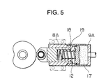
- Fig. 5 shows a modification of the first embodiment, and threaded portions 18 and 19 are provided respectively on a slide guide 8A and a cylinder 9A, and the slide guide 8A and the cylinder 9A are threadedly connected together, thus providing a mechanism for adjusting the spring force of the coil spring 12.
- the compression force of the coil spring 12 can be changed, and hence its spring force can be adjusted. Therefore, the initial torque compensation value by the coil spring 12 can be adjusted, and also the minimum torque compensation value, obtained with no air present in the air chamber 17, can be made smaller, and the maximum torque compensation value, obtained with the air fully filled in the air chamber 17, can be made larger.
- the air is supplied to the air chamber 17 if necessary, and thus the compensation torque is produced by the spring pressure and the air pressure, and therefore the fluctuation torque of the motion conversion apparatus can be positively suppressed regardless of the rotational speed. And besides, since the air chamber 17 is separate from the space receiving the coil spring 12, the air-tightness of the air chamber 17 can be relatively easily maintained. Further, by providing the mechanism for adjusting the pressing force of the coil spring 12, the initial value of the compensation torque can be adjusted, and also the range of the compensation torque value between its minimum and maximum values can be widened.
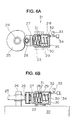
- Fig. 6 shows the construction of a fluctuation torque cancellation apparatus of the parallel type according to a second embodiment of the invention.
- This fluctuation torque cancellation apparatus 21 is fixedly secured to a motion conversion apparatus 22 by mounting bolts 23.
- the fluctuation torque cancellation apparatus 21 includes a torque compensation cam 25 fixedly mounted on a rotation shaft 24 serving as an input/output shaft of the motion conversion apparatus 22, and the torque compensation cam 25 is engaged with a cam follower 26.
- the cam follower 26 is rotatably supported on a distal end portion of a piston 27, and the piston 27 is slidably received in a cylinder 28.
- a piston rod 29 is formed on and projects from an inner surface of an end wall of the cylinder 28 toward the piston 27, and a compression coil spring 30 is wound around the piston rod 29, and is provided between a cylindrical portion of the piston 27 and the end wall of the cylinder 28.
- Seal members 31 are mounted on an outer peripheral surface of the piston 27, and form an air-tight seal between an inner peripheral surface of the cylinder 28 and the outer peripheral surface of the piston 27.
- An air supply port 32 is formed through the end wall of the cylinder 28, and an air source 34, having a pressure control device 33, is connected to the air supply port 32. The air is supplied from the air source 34 to an air chamber 35 defined by the piston 27 and the cylinder 28.
- Fig. 7 shows a modification of the second embodiment, and the cylinder 28 is divided into a cylinder 28A of a cylindrical shape and a cap-like cylinder cover 28B, and threaded portions 36 and 37 are provided respectively on the cylinder 28A and the cylinder cover 28B, and the cylinder 28A and the cylinder cover 28B are threadedly connected together, and a seal member 38 is provided between an inner peripheral surface of the cylinder cover 28B and an outer peripheral surface of the cylinder 28A.
- the apparatus can be formed into a compact construction. Further, by providing the mechanism for adjusting the pressing force of the coil spring 30, the initial value of the compensation torque can be adjusted, and also the range of the compensation torque value between its minimum and maximum values can be widened.
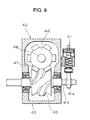
- Fig. 8 show a third embodiment of a fluctuation torque cancellation apparatus of the invention and a motion conversion apparatus.
- the fluctuation torque cancellation apparatus 41 is of the serial type as shown in Fig. 1, but may be of the parallel type as shown in Fig. 5.
- the fluctuation torque cancellation apparatus 41 is fixedly secured to a side surface of a housing 43 of the motion conversion apparatus 42, and a torque compensation cam 41a of the apparatus 41 is fixedly mounted on that portion of an input shaft 44 projecting outwardly from the side surface of the housing 43, the input shaft 44 extending through the housing 43.
- a roller gear cam 45 is fixedly mounted on the input shaft 44 within the housing 43.
- a plurality of cam followers 47 provided on an outer peripheral surface of a turret 46, are sequentially brought into engagement with the roller gear cam 45, and a continuous rotational motion of the roller gear cam 45 is converted into an intermittent rotational motion of the turret 46, and is outputted from an output shaft 48 provided at a central portion of the turret 46.
- the roller gear cam mechanism is used as a cam transmission mechanism of the motion conversion apparatus 42, the continuous rotational motion of the input shaft 44 can be positively converted into the intermittent rotational motion of the output shaft 48. And besides, since the torque compensation cam 41a of the fluctuation torque cancellation apparatus 41 is connected directly to the input shaft 44, there are advantages that the construction is simple, and that the maintenance can be easily effected.
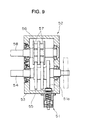
- Fig. 9 shows a fourth embodiment of a fluctuation torque cancellation apparatus of the invention and a motion conversion apparatus.
- the fluctuation torque cancellation apparatus 51 is of the serial type as shown in Fig. 1, but may be of the parallel type as shown in Fig. 5.
- the fluctuation torque cancellation apparatus 51 is fixedly secured to a lower surface of a housing 53 of the motion conversion apparatus 52, and a torque compensation cam 51a of the apparatus 51 is fixedly mounted on that portion of an input shaft 54 disposed within the housing 53, the input shaft 54 extending through the housing 53.
- a parallel cam 55 is fixedly mounted on the input shaft 54 within the housing 53, and a plurality of cam followers 57, provided on a turret 56, are sequentially brought into engagement with the parallel cam 55, and a continuous rotational motion of the parallel cam 55 is converted into an intermittent rotational motion of the turret 56, and is outputted from an output shaft 58 provided at a central portion of the turret 56.
- the parallel cam mechanism is used as a cam transmission mechanism of the motion conversion apparatus 52, the continuous rotational motion of the input shaft 54 can be positively converted into the intermittent rotational motion of the output shaft 58.
- the torque compensation cam 51a of the fluctuation torque cancellation apparatus 52 is provided within the motion conversion apparatus 52, the fluctuation torque cancellation apparatus 51 can be formed into a compact construction.
- a barrel cam mechanism or a cylindrical cam mechanism may be used as the cam transmission mechanism of the motion conversion apparatus, and in this case, also, the continuous rotational motion of the input shaft can be positively converted into the intermittent rotational motion of the output shaft.
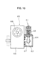
- Fig. 10 shows a fifth embodiment of a fluctuation torque cancellation apparatus of the invention and a motion conversion apparatus.
- the fluctuation torque cancellation apparatus 61 is of the serial type as shown in Fig. 1, but may be of the parallel type as shown in Fig. 5.
- a torque compensation cam 62 is housed or contained in a cam cover 64 fixedly secured to a slide guide 63, and the cam cover 64 is fixedly secured to a side surface of a housing 66 of the motion conversion apparatus 65.
- the torque compensation cam 62 is fixedly mounted on that portion of an input shaft 67 projecting outwardly from the housing 66, the input shaft 67 extending through the housing 66.
- a continuous rotational motion of the input shaft 67 is converted into an intermittent rotational motion of an output shaft 68, and is outputted from this output shaft 68.
- the torque compensation cam 62 is covered with the cam cover 64, dust and the like are prevented from depositing on a cam surface of the cam 62.
- Fig. 11 shows a sixth embodiment of a fluctuation torque cancellation apparatus of the invention and a motion conversion apparatus.
- the fluctuation torque cancellation apparatus 71 is of the serial type as shown in Fig. 1, but may be of the parallel type as shown in Fig. 5.
- a torque compensation cam 72 is housed in a cam cover 74 fixedly secured to a slide guide 73, and is fixedly mounted on a rotation shaft 75 extending through the cam cover 74.
- a pulley 76 is fixedly mounted on that portion of the rotation shaft 75 projecting outwardly from the cam cover 74.
- a pulley 80 is fixedly mounted on that portion of an input shaft 79 projecting outwardly from a housing 78 of the motion conversion apparatus 77, and a belt 81 is extended around the two pulleys 76 and 80.
- a continuous rotational motion of the input shaft 79 is converted into an intermittent rotational motion of an output shaft 82, and is outputted from this output shaft 82.
- the fluctuation torque cancellation apparatus 71 can be formed as a unit, and can be installed at a position spaced from the motion conversion apparatus 77.
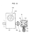
- Fig. 12 shows a seventh embodiment of a fluctuation torque cancellation apparatus of the invention and a motion conversion apparatus.
- the fluctuation torque cancellation apparatus 91 is of the same construction as that of the fluctuation torque cancellation apparatus shown in Fig. 11, and a torque compensation cam 92 of the apparatus 91 is housed in a cam cover 94 fixedly secured to a slide guide 93, and is fixedly mounted on a rotation shaft 95 extending through the cam cover 94.
- One end of the rotation shaft 95, disposed exteriorly of the cam cover 94, is connected by a coupling 99 to one end portion of an input shaft 98 projecting outwardly from a housing 97 of the motion conversion apparatus 96.
- a continuous rotational motion of the input shaft 98 is converted into an intermittent rotational motion of an output shaft 100, and is outputted from this output shaft 100.
- the fluctuation torque cancellation apparatus 91 can be formed as a unit, and can be installed at a position spaced from the motion conversion apparatus 96.
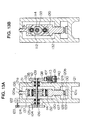
- FIG. 13 shows a pressing machine incorporating a motion conversion apparatus having an eighth embodiment of a fluctuation torque cancellation apparatus of the invention.
- a frame 121 of this pressing machine has a box-shape, and includes an upper support portion 121a, an intermediate support portion 121b and a lower support portion 121c.
- An upper guide portion 120a of a slide 120 slidably extends through the upper support portion 121a of the frame 121 through a bearing 126 for vertical (upward and downward) movement, and a lower guide portion 120b of the slide 120 slidably extends through the intermediate support portion 121b of the frame 121 through a bearing 127 for vertical movement.
- An upper die 128 is mounted on a lower end of the slide 120, and a lower die 129 is mounted on the lower support portion 121c of the frame 121 through a bolster 130.
- a pair of upper and lower cam followers 131 and 132 are rotatably mounted on an intermediate portion of the slide 120 through respective needles 137 and 138.
- An input shaft 114 extends horizontally through the intermediate portion of the slide 120 between the pair of cam followers 131 and 132.
- a heart-shaped drive plate cam 133 is fixedly mounted on the input shaft 114, and is interposed between and held in contact with the pair of cam followers 131 and 132.
- the input shaft 114 is rotatably supported at its opposite end portions on the frame 121 through bearings 134 and 135.
- a flywheel 125 is fixedly mounted on one end of the input shaft 114 through a shaft-fastening element 136, and this flywheel 125 is rotated through a belt 124 and a pulley 123 fixedly mounted on a rotation shaft of a motor 122 mounted on the upper support portion 121a of the frame 121.
- a torque compensation cam 112 of the fluctuation torque cancellation apparatus 101 is fixedly mounted on the other end of the input shaft 114 through a fastening element 139.
- the above pressing machine operates as follows.
- the motor 122 When the motor 122 is rotated, its rotational force is transmitted via the pulley 123 and the belt 124 to the flywheel 125 to rotate the input shaft 114, so that the slide 120 reciprocally moves linearly upward and downward through the drive plate cam 133 and the pair of cam followers 131 and 132, and a workpiece is worked or processed between the upper die 128, mounted on the slide 120, and the lower die 130 mounted on the lower support portion 121c of the frame 121.
- the fluctuation torque cancellation apparatus 101 operates to cancel a load fluctuation torque exerted on the input shaft 114.
- the fluctuation torque cancellation apparatus of this eighth embodiment is connected to the input shaft 114 of the pressing machine incorporating the motion conversion apparatus for converting the continuous rotational motion of the input shaft 114 into the linear reciprocal motion of the slide 120.
- the fluctuation torque cancellation apparatus 101 of this eighth embodiment itself is similar in construction to the fluctuation torque cancellation apparatus of Fig. 1 except that the torque compensation cam 112 is so shaped as to cancel the fluctuation torque acting on the input shaft 114 during the time when the slide 120 reciprocally moves to work the workpiece.
- the fluctuation torque cancellation apparatus 101 includes a slider 107, a slide guide 113, an air supply port 140 and so on.
- the torque compensation value can be adjusted, and the basic torque compensation is effected by the spring pressure, and when adjusting the torque compensation value, the air pressure is used, so that the torque compensation value can be varied in accordance with the rotational speed.
- the torque compensation value is basically ensured by the spring pressure, and therefore even if an air leakage should occur, there is no problem.
- the spring pressure can be made smaller as compared with the conventional construction, and therefore the degree of compressing of the spring during the assembling operation is decreased, and the efficiency of the assembling operation can be enhanced.
Landscapes
- Engineering & Computer Science (AREA)
- General Engineering & Computer Science (AREA)
- Mechanical Engineering (AREA)
- Transmission Devices (AREA)
- Press Drives And Press Lines (AREA)
Claims (13)
- Fluktuationsdrehmomentaufhebungs- bzw. -ausgleichseinrichtung für das Aufheben bzw. Ausgleichen eines auf eine Rotationswelle (4; 24; 44; 54; 67; 79; 98; 114) einer Bewegungsumwandlungseinrichtung (2; 22; 42; 52; 65; 77; 96) wirkenden Fluktuationsdrehmoments, umfassend eine Drehmomentkompensationsnocke bzw. einen Drehmomentkompensationskurvenkörper (5; 25; 41a; 51a; 62; 72; 92; 112), die bzw. der dazu geeignet ist, mit der Rotationswelle zur Rotation mit derselben verbunden zu werden, einen Nocken- bzw. Kurvenkörperfolger (6; 26), der in Rolleingriff mit einer Nocken- bzw. Kurvenkörperoberfläche der Nocke bzw. des Kurvenkörpers gehalten wird, ein Schieberteil (7; 27; 107), das den Nocken- bzw. Kurvenkörperfolger drehbar hält, einen Zylinder (9; 9A; 28; 28A), der das Schieberteil verschiebbar aufnimmt, ein mechanisches Federteil (12; 30), das in dem Zylinder zum elastischen Drücken bzw. Antreiben des Schieberteils nach der Nocke bzw. dem Kurvenkörper zu angebracht ist, so dass es dadurch den Nocken- bzw. Kurvenkörperfolger gegen die Nocken- bzw. Kurvenkörperoberfläche drückt, dadurch gekennzeichnet, dass:
der Zylinder eine darin defnierte bzw. begrenzte Luftkammer (17; 35) hat und Mittel (14, 15, 16; 32, 33, 34; 140) zum Zuführen einer eingestellten Menge an Luft in die Luftkammer in dem Zylinder vorgesehen sind. - Einrichtung gemäß Anspruch 1, dadurch gekennzeichnet, dass ein Raum in dem Zylinder, welcher das Federteil (12) aufnimmt, von der Luftkammer (17) durch einen Kolben (10) getrennt ist, welcher verschiebbar in dem Zylinder angebracht ist, und das Federteil zwischen dem Schieberteil und dem Kolben so vorgesehen ist, dass es aufgeweitet und verkürzt wird.
- Einrichtung gemäß Anspruch 1, dadurch gekennzeichnet, dass die Luftkammer (35) in dem Zylinder außerdem als ein Raum dient, der das Federteil (30) aufnimmt.
- Einrichtung gemäß Anspruch 2 oder 3, dadurch gekennzeichnet, dass ein Mittel (18, 19; 36, 37, 38) zum Einstellen der Federkraft des Federteils vorgesehen ist.
- Einrichtung gemäß irgendeinem der Ansprüche 1 bis 4, dadurch gekennzeichnet, dass die Bewegungsumwandlungseinrichtung einen Nocken- bzw. Kurvenkörperübertragungsmechanismus (45, 46, 47; 55, 56, 57) aufweist und die Rotationswelle der Bewegungsumwandlungseinrichtung eine der folgenden ist: eine Eingangswelle (4; 24; 44; 54; 67; 79; 98), die eine Schaltnocke bzw. einen Schaltkurvenkörper (45; 55) hat, eine Ausgangswelle (48; 58; 68, 82; 100), die fest auf einem Drehkopf (46; 56) angebracht ist, der Nocken- bzw. Kurvenkörperfolger (47; 57) hat, die mit der Schaltnocke bzw. dem Schaltkurvenkörper in Eingriff sind.
- Einrichtung gemäß Anspruch 5, dadurch gekennzeichnet, dass der Nocken- bzw. Kurvenkörperübertragungsmechanismus ein Rollenzahnrad- bzw. -getriebenocken- bzw. -kurvenkörpermechanismus (45, 46, 47) ist.
- Einrichtung gemäß Anspruch 5, dadurch gekennzeichnet, dass der Nocken- bzw. Kurvenkörperübertragungsmechanimus ein Parallelnocken- bzw. -kurvenkörpermechanismus (55, 56, 57) ist.
- Einrichtung gemäß Anspruch 5, dadurch gekennzeichnet, dass der Nocken- bzw. Kurvenkörperübertragungsmechanismus ein Trommelnocken- bzw. -kurvenkörpermechanismus ist.
- Einrichtung gemäß irgendeinem der Ansprüche 1 bis 8, dadurch gekennzeichnet, dass die Drehmomentkompensationsnocke bzw. der Drehmomentkompensationskurvenkörper fest auf jenem Teil der Rotationswelle angebracht ist, der in der Bewegungsumwandlungseinrichtung aufgenommen ist (Figur 9).
- Einrichtung gemäß irgendeinem der Ansprüche 1 bis 8, dadurch gekennzeichnet, dass die Drehmomentkompensationsnocke bzw. der Drehmomentkompensationskurvenkörper fest auf jenem Teil der Rotationswelle angebracht ist, der von der Bewegungsumwandlungseinrichtung nach auswärts vorsteht (Figuren 1B, 6B, 8, 10, 13A).
- Einrichtung gemäß Anspruch 10, dadurch gekennzeichnet, dass die Drehmomentkompensationsnocke bzw. der Drehmomentkompensationskurvenkörper mit einer Nokken- bzw. Kurvenkörperabdeckung (64; 74; 94) abgedeckt ist.
- Einrichtung gemäß Anspruch 11, dadurch gekennzeichnet, dass die Drehmomentkompensationsnocke bzw. der Drehmomentkompensationskurvenkörper fest auf einer Rotationswelle (75; 95) angebracht ist, die in der Nocken- bzw. Kurvenkörperabdeckung (74; 94) angebracht ist, und dass die Rotationswelle (75; 95) mit der Rotationswelle (79; 98) der Bewegungsumwandlungseinrichtung über ein Leistungs- bzw. Kraftübertragungsmittel (76, 80, 81; 99) verbunden ist.
- Einrichtung gemäß Anspruch 1, dadurch gekennzeichnet, dass die Rotationswelle eine Eingangswelle (114) einer Pressmaschine ist, welche die Bewegungsumwandlungseinrichtung enthält bzw. in welche die Bewegungsumwandlungseinrichtung eingebaut ist, die so aufgebaut ist, dass sie eine kontinuierliche Rotationsbewegung der Eingangswelle in eine hin- und hergehende Linearbewegung eines Schlittens (120) der Pressmaschine umwandelt.
Applications Claiming Priority (3)
| Application Number | Priority Date | Filing Date | Title |
|---|---|---|---|
| JP09820796A JP3742143B2 (ja) | 1996-04-19 | 1996-04-19 | 変動トルク相殺装置 |
| JP98207/96 | 1996-04-19 | ||
| JP9820796 | 1996-04-19 |
Publications (3)
| Publication Number | Publication Date |
|---|---|
| EP0802351A2 EP0802351A2 (de) | 1997-10-22 |
| EP0802351A3 EP0802351A3 (de) | 1998-10-28 |
| EP0802351B1 true EP0802351B1 (de) | 2001-12-05 |
Family
ID=14213549
Family Applications (1)
| Application Number | Title | Priority Date | Filing Date |
|---|---|---|---|
| EP97106146A Expired - Lifetime EP0802351B1 (de) | 1996-04-19 | 1997-04-15 | Vorrichtung zum Ausgleich von Momentschwankungen |
Country Status (5)
| Country | Link |
|---|---|
| US (1) | US6000298A (de) |
| EP (1) | EP0802351B1 (de) |
| JP (1) | JP3742143B2 (de) |
| KR (1) | KR100255398B1 (de) |
| DE (1) | DE69708738T2 (de) |
Cited By (1)
| Publication number | Priority date | Publication date | Assignee | Title |
|---|---|---|---|---|
| DE10139161B4 (de) * | 2000-12-07 | 2007-08-02 | Bongioanni Macchine S.P.A., Fossano | Schnellpressen zur Herstellung von Ziegeln |
Families Citing this family (27)
| Publication number | Priority date | Publication date | Assignee | Title |
|---|---|---|---|---|
| JP3276331B2 (ja) * | 1998-03-13 | 2002-04-22 | 株式会社ミツトヨ | 定圧力機構及び定トルク機構 |
| DE19914627B4 (de) * | 1999-03-31 | 2011-05-12 | Heidelberger Druckmaschinen Ag | Verfahren und Vorrichtung zur Kompensation der Drehschwingungen einer Druckmaschine |
| DE19914613A1 (de) * | 1999-03-31 | 2000-10-05 | Heidelberger Druckmasch Ag | Verfahren und Vorrichtung zur Tilgung der Drehschwingungen einer Druckmaschine |
| US6305279B1 (en) * | 1999-05-10 | 2001-10-23 | Fitel Innovations | Tool drive apparatus |
| JP3458306B2 (ja) * | 1999-09-10 | 2003-10-20 | 山久チヱイン株式会社 | ワーク搬送用駆動装置 |
| FR2802264B1 (fr) * | 1999-12-10 | 2002-07-26 | Renault | Dispositif d'equilibrage d'un moteur thermique |
| DE10217707A1 (de) * | 2002-04-17 | 2003-11-06 | Heidelberger Druckmasch Ag | Kompensation von Zylinderschwingungen in bedruckstoffverarbeitenden Maschinen |
| DE10320760B4 (de) * | 2002-06-10 | 2016-12-29 | Heidelberger Druckmaschinen Ag | Ausgleichsmomenten-Schaltung |
| DE10249109A1 (de) * | 2002-10-21 | 2004-05-06 | Eckold Gmbh & Co Kg | Werkzeug zum mechanischen Bearbeiten von Werkstücken |
| CN1771402A (zh) * | 2003-10-20 | 2006-05-10 | 帕斯卡工程株式会社 | 旋转轴用平衡器机构 |
| US6978749B2 (en) * | 2003-10-27 | 2005-12-27 | Borgwarner Inc. | Means to add torsional energy to a camshaft |
| KR101049190B1 (ko) * | 2008-04-21 | 2011-07-14 | 최영수 | 공기압을 이용한 동력발생장치 |
| FR2931235B1 (fr) * | 2008-05-13 | 2010-06-04 | Peugeot Citroen Automobiles Sa | Dispositif generateur de couple acyclique pilote et arbre rotatif presentant un tel dispositif |
| JP5205332B2 (ja) * | 2009-04-30 | 2013-06-05 | 東京計器株式会社 | 耐圧疲労試験装置 |
| JP2011075074A (ja) * | 2009-10-01 | 2011-04-14 | Meiyu-Giken Co Ltd | 永久磁石を用いた往復動緩衝装置 |
| JP5496696B2 (ja) * | 2010-01-27 | 2014-05-21 | Ntn株式会社 | ポンプ用タペット |
| CN103016663B (zh) * | 2011-09-22 | 2016-08-17 | 上海雅盟机械制造有限公司 | 一种通过凸轮轨迹改变实现转移作用力的装置 |
| JP2014103869A (ja) * | 2012-11-26 | 2014-06-09 | Yanmar Co Ltd | 植付部のトルク平準化機構 |
| JP3182205U (ja) * | 2012-12-26 | 2013-03-14 | 株式会社シマノ | 自転車用制御装置 |
| JP3182209U (ja) * | 2012-12-26 | 2013-03-14 | 株式会社シマノ | 自転車用制御装置 |
| CN103407186B (zh) * | 2013-07-31 | 2015-09-16 | 郑州市旭祥砂轮有限公司 | 一种弹簧强压机 |
| US9651133B2 (en) * | 2015-02-04 | 2017-05-16 | Google Inc. | Phased joint cam |
| ITUB20156042A1 (it) * | 2015-11-11 | 2017-05-11 | Giobbe Srl | Cinematismo in asse alettrico programmabile per il comando di un albero a moto alterno con recupero di energia |
| JP6477634B2 (ja) * | 2016-09-05 | 2019-03-06 | 株式会社豊田中央研究所 | 駆動力伝達装置 |
| CN107282833B (zh) * | 2017-05-31 | 2019-07-05 | 杭州欣湖弹簧有限公司 | 一种弹簧压并机 |
| KR102114888B1 (ko) * | 2019-05-07 | 2020-05-25 | 권오섭 | 트레이 모듈 및 이를 이용한 시공방법 |
| WO2020234790A1 (en) * | 2019-05-20 | 2020-11-26 | Majid Abedinzadeh Shahri | Unidirectional spring |
Family Cites Families (14)
| Publication number | Priority date | Publication date | Assignee | Title |
|---|---|---|---|---|
| US1738876A (en) * | 1924-05-23 | 1929-12-10 | Willys Overland Co | Engine balancer |
| US1753020A (en) * | 1924-10-20 | 1930-04-01 | Maschf Augsburg Nuernberg Ag | Reversible internal-combustion engine of the fuel-injection type |
| US2423701A (en) * | 1945-01-01 | 1947-07-08 | Marquette Metal Products Co | Pump |
| US2543649A (en) * | 1950-07-12 | 1951-02-27 | Gen Electric | Linkage for hydraulic actuators |
| DE2637314C2 (de) * | 1976-08-19 | 1983-12-15 | Carl Still Gmbh & Co Kg, 4350 Recklinghausen | Einrichtung für die automatische periodische Umsteuerung der Regenerativ- Beheizung von Verkokungsbatterien |
| US4352296A (en) * | 1980-09-18 | 1982-10-05 | General Motors Corporation | Chatter free gear driven cam actuated vacuum pump |
| JPS604665A (ja) * | 1983-06-23 | 1985-01-11 | Otsuka Kamu Kk | カムインデツクス装置 |
| US4658608A (en) * | 1984-11-09 | 1987-04-21 | Fox Douglas M | Security valve mechanism for a hydraulic system |
| DE3626185A1 (de) * | 1986-08-01 | 1988-02-18 | Heidelberger Druckmasch Ag | Getriebe zur bildung einer zyklisch ablaufenden bewegung aus einer rotationsbewegung |
| US4955243A (en) * | 1989-05-03 | 1990-09-11 | Sankyo Manufacturing Company, Ltd. | Motion transforming apparatus |
| JPH07116897A (ja) * | 1993-10-26 | 1995-05-09 | Sankyo Seisakusho:Kk | 機械式プレス装置 |
| US5544537A (en) * | 1994-01-21 | 1996-08-13 | Paper Machinery Corporation | Energy balance system configured to compensate for the changes in energy absorbed by a rotating shaft |
| JPH08210457A (ja) * | 1994-12-01 | 1996-08-20 | Shikoku Kakoki Co Ltd | カム装置 |
| JP3907742B2 (ja) * | 1996-04-01 | 2007-04-18 | 株式会社三共製作所 | 運動変換装置 |
-
1996
- 1996-04-19 JP JP09820796A patent/JP3742143B2/ja not_active Expired - Lifetime
-
1997
- 1997-04-15 EP EP97106146A patent/EP0802351B1/de not_active Expired - Lifetime
- 1997-04-15 DE DE69708738T patent/DE69708738T2/de not_active Expired - Lifetime
- 1997-04-17 US US08/840,863 patent/US6000298A/en not_active Expired - Fee Related
- 1997-04-18 KR KR1019970014315A patent/KR100255398B1/ko not_active Expired - Fee Related
Cited By (1)
| Publication number | Priority date | Publication date | Assignee | Title |
|---|---|---|---|---|
| DE10139161B4 (de) * | 2000-12-07 | 2007-08-02 | Bongioanni Macchine S.P.A., Fossano | Schnellpressen zur Herstellung von Ziegeln |
Also Published As
| Publication number | Publication date |
|---|---|
| EP0802351A3 (de) | 1998-10-28 |
| US6000298A (en) | 1999-12-14 |
| JPH09277094A (ja) | 1997-10-28 |
| JP3742143B2 (ja) | 2006-02-01 |
| KR100255398B1 (ko) | 2000-08-01 |
| DE69708738T2 (de) | 2002-05-08 |
| DE69708738D1 (de) | 2002-01-17 |
| EP0802351A2 (de) | 1997-10-22 |
Similar Documents
| Publication | Publication Date | Title |
|---|---|---|
| EP0802351B1 (de) | Vorrichtung zum Ausgleich von Momentschwankungen | |
| US5544576A (en) | Mechanical pressing machine having a load fluctuating torque cancelling device | |
| US4433755A (en) | Elevator apparatus | |
| JPS61228155A (ja) | エンジンの補機駆動装置 | |
| EP1570979A1 (de) | Hubantriebsmechanismus und diesen verwendende presse | |
| ITTO940856A1 (it) | Pressa meccanica. | |
| JPH08141684A (ja) | 鍛造機 | |
| CN107245844B (zh) | 洗衣机及其减速离合器 | |
| US3914977A (en) | Presses and the like | |
| CN116493618A (zh) | 一种数控机床智能电主轴系统 | |
| US6009773A (en) | Motion conversion apparatus | |
| US4955243A (en) | Motion transforming apparatus | |
| US4607732A (en) | Drive mechanism for a mechanical press | |
| CN208944943U (zh) | 冲床及其飞轮 | |
| US5603245A (en) | Method for a translatory motion of components | |
| CN206884276U (zh) | 模切辊设备和印刷模切装置 | |
| KR100310389B1 (ko) | 리벳팅 장치 | |
| JPH10328891A (ja) | プレス機械 | |
| US20250229313A1 (en) | Press brake and table driving method for press brake | |
| CN107415320B (zh) | 模切辊设备和印刷模切装置 | |
| JPH01120472A (ja) | 運動変換装置 | |
| CN222310713U (zh) | 一种转向机上无级自动补偿齿轮齿条间隙的压紧机构 | |
| JPH10267105A (ja) | 変動トルク相殺装置 | |
| CN101737470A (zh) | 含运动-停歇运动模式的自动化机械系统的节能减振方法 | |
| SU1180142A1 (ru) | Подающее устройство к радиально-обжимной машине |
Legal Events
| Date | Code | Title | Description |
|---|---|---|---|
| PUAI | Public reference made under article 153(3) epc to a published international application that has entered the european phase |
Free format text: ORIGINAL CODE: 0009012 |
|
| 17P | Request for examination filed |
Effective date: 19970415 |
|
| AK | Designated contracting states |
Kind code of ref document: A2 Designated state(s): DE GB IT |
|
| PUAL | Search report despatched |
Free format text: ORIGINAL CODE: 0009013 |
|
| AK | Designated contracting states |
Kind code of ref document: A3 Designated state(s): DE GB IT |
|
| 17Q | First examination report despatched |
Effective date: 20000518 |
|
| GRAG | Despatch of communication of intention to grant |
Free format text: ORIGINAL CODE: EPIDOS AGRA |
|
| GRAG | Despatch of communication of intention to grant |
Free format text: ORIGINAL CODE: EPIDOS AGRA |
|
| GRAH | Despatch of communication of intention to grant a patent |
Free format text: ORIGINAL CODE: EPIDOS IGRA |
|
| GRAH | Despatch of communication of intention to grant a patent |
Free format text: ORIGINAL CODE: EPIDOS IGRA |
|
| GRAA | (expected) grant |
Free format text: ORIGINAL CODE: 0009210 |
|
| AK | Designated contracting states |
Kind code of ref document: B1 Designated state(s): DE GB IT |
|
| REG | Reference to a national code |
Ref country code: GB Ref legal event code: IF02 |
|
| REF | Corresponds to: |
Ref document number: 69708738 Country of ref document: DE Date of ref document: 20020117 |
|
| PLBE | No opposition filed within time limit |
Free format text: ORIGINAL CODE: 0009261 |
|
| STAA | Information on the status of an ep patent application or granted ep patent |
Free format text: STATUS: NO OPPOSITION FILED WITHIN TIME LIMIT |
|
| 26N | No opposition filed | ||
| PGFP | Annual fee paid to national office [announced via postgrant information from national office to epo] |
Ref country code: DE Payment date: 20110413 Year of fee payment: 15 |
|
| PGFP | Annual fee paid to national office [announced via postgrant information from national office to epo] |
Ref country code: GB Payment date: 20110413 Year of fee payment: 15 |
|
| PGFP | Annual fee paid to national office [announced via postgrant information from national office to epo] |
Ref country code: IT Payment date: 20110421 Year of fee payment: 15 |
|
| GBPC | Gb: european patent ceased through non-payment of renewal fee |
Effective date: 20120415 |
|
| PG25 | Lapsed in a contracting state [announced via postgrant information from national office to epo] |
Ref country code: GB Free format text: LAPSE BECAUSE OF NON-PAYMENT OF DUE FEES Effective date: 20120415 |
|
| REG | Reference to a national code |
Ref country code: DE Ref legal event code: R119 Ref document number: 69708738 Country of ref document: DE Effective date: 20121101 |
|
| PG25 | Lapsed in a contracting state [announced via postgrant information from national office to epo] |
Ref country code: IT Free format text: LAPSE BECAUSE OF NON-PAYMENT OF DUE FEES Effective date: 20120415 |
|
| PG25 | Lapsed in a contracting state [announced via postgrant information from national office to epo] |
Ref country code: DE Free format text: LAPSE BECAUSE OF NON-PAYMENT OF DUE FEES Effective date: 20121101 |