EP0802290B1 - Kodiervorrichtung und Koderegistriervorrichtung für Möbelschlösser oder dergleichen - Google Patents
Kodiervorrichtung und Koderegistriervorrichtung für Möbelschlösser oder dergleichen Download PDFInfo
- Publication number
- EP0802290B1 EP0802290B1 EP97400853A EP97400853A EP0802290B1 EP 0802290 B1 EP0802290 B1 EP 0802290B1 EP 97400853 A EP97400853 A EP 97400853A EP 97400853 A EP97400853 A EP 97400853A EP 0802290 B1 EP0802290 B1 EP 0802290B1
- Authority
- EP
- European Patent Office
- Prior art keywords
- coding
- wheels
- buttons
- plate
- bolt
- Prior art date
- Legal status (The legal status is an assumption and is not a legal conclusion. Google has not performed a legal analysis and makes no representation as to the accuracy of the status listed.)
- Expired - Lifetime
Links
- 239000002184 metal Substances 0.000 claims description 3
- 229910052751 metal Inorganic materials 0.000 claims description 3
- 239000000523 sample Substances 0.000 claims 3
- 230000003213 activating effect Effects 0.000 claims 1
- 230000004913 activation Effects 0.000 claims 1
- 150000002739 metals Chemical class 0.000 claims 1
- 230000006870 function Effects 0.000 description 2
- 230000009471 action Effects 0.000 description 1
- 230000008859 change Effects 0.000 description 1
- 210000000038 chest Anatomy 0.000 description 1
- 239000006185 dispersion Substances 0.000 description 1
- 230000000694 effects Effects 0.000 description 1
- 230000005484 gravity Effects 0.000 description 1
- 230000014759 maintenance of location Effects 0.000 description 1
- 230000007246 mechanism Effects 0.000 description 1
- 230000004048 modification Effects 0.000 description 1
- 238000012986 modification Methods 0.000 description 1
- 239000011435 rock Substances 0.000 description 1
Images


Classifications
-
- E—FIXED CONSTRUCTIONS
- E05—LOCKS; KEYS; WINDOW OR DOOR FITTINGS; SAFES
- E05B—LOCKS; ACCESSORIES THEREFOR; HANDCUFFS
- E05B37/00—Permutation or combination locks; Puzzle locks
- E05B37/12—Permutation or combination locks; Puzzle locks with tumbler discs on several axes
-
- E—FIXED CONSTRUCTIONS
- E05—LOCKS; KEYS; WINDOW OR DOOR FITTINGS; SAFES
- E05B—LOCKS; ACCESSORIES THEREFOR; HANDCUFFS
- E05B19/00—Keys; Accessories therefor
- E05B19/20—Skeleton keys; Devices for picking locks; Other devices for similar purposes ; Means to open locks not otherwise provided for, e.g. lock pullers
- E05B19/205—Lock decoders
Definitions
- the invention relates to a coding device comprising a new device for locating said coding of locks for furniture, for example for locker room furniture, chests and the like for temporary storage various objects by the public.
- the invention solves this problem by ensuring that it is impossible to reconstruct the coding combination without having a particular device that may not be accessible specialized personnel who can be stored in a safe or the like.
- the device for coding and locating said coding for furniture locks and the like comprising a bolt operable by a tree from a knob outside the cabinet is characterized in that it comprises step-by-step coding buttons for also step-by-step drive of coding wheels presenting each a notch and a magnet, said coding wheels being arranged around a swash plate comprising fingers that got into the notches of the different encoder wheels when establishing a combination coded by rotation of the coding buttons with respect to a graduation of a front plate, the exit of the bolt by the maneuvering a tree causing the erasure of a dog and the swiveling of the swash plate so that the coding freely drive the coding wheels without it is possible to retract the bolt while maintained by the dog and a finger of the swash plate, sleeves being provided near the coding wheels for setting up a magnetic detector making the position of the magnet each coding wheel can be identified using said detector in case of forgetting the coded combination so as to find the combination.
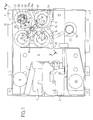
- Fig. 1 is a diagrammatic elevation, partially broken away, of the coding device for a lock according to the invention.
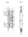
- Fig. 2 is a section taken substantially along the line II-II of fig. 1.
- Fig. 3 is a schematic elevation, similar to FIG. 1, illustrating a characteristic position of the device.
- Fig. 4 is a schematic elevation, similar to FIG. 1, showing particular elements that the device.
- Fig. 5 is a sectional elevation of the device member allowing the location of the code.
- the device illustrated by figs. 1, 3 and 4, includes a case 1, for example in folded sheet, inside which there is a compartment 2 for a coin-operated device designated as a whole by the reference 3.
- the device coin mechanism not directly part of the invention is not described in detail in the following but is simply illustrated to show the position of a piece of currency or other token 4.
- the part 4 is provided to descend along a ramp of 5 to pass through a passage 6 in which it occupies at a time position 4, this piece, when released, falling to the position 4b .
- a dog 9 whose function is described in the following is articulated on an axis 14 and comprises two branches 15, respectively 16.
- the branch 16 is used to lock a bolt 19 when the latter came out as illustrated in FIG. 3, position in which said branch 16 enters a notch 20 of said bolt, which is shown in FIG. 3.
- the bolt 19 is moved by a lever 17 mounted on a shaft maneuver 18 operated from outside the housing 1.
- the housing 1 contains a guide plate 21 which is there fixed and in which notched openings are made 22.
- the number of notches 23 is normally ten for correspond to a graduation constituted for example for numbers 0 to 9 carried on a front panel 24 by which pass coding buttons 25 which can be advanced step by step not from one notch to another by means of balls 26 (fig. 2) which they contain and which are pushed by springs 27 in the successive notches 23.
- the coding buttons 25 have a core or shaft 28 mounted in a bearing 29.
- the bearings 29 are formed by encoder wheels 30 which can be driven by balls 31 pushed by springs 32.
- the balls 31 and the springs 32 appear in fig. 1 and are shown schematically in fig. 2. They can be angularly offset by compared to balls 26 and springs 27.
- the coding wheels 30 also each delimit ten notches designated by 33 in fig. 1.
- the periphery of the coding wheels 30 has for each of them a notch 34, 34 a , 34 b , 34 c ...
- the encoder wheels are each provided with a small magnet 35 placed opposite the guide plate 21 which is provided with sets of metal studs 36 arranged in look of each coding button as illustrated in figs. 1 and 4.
- the device includes a swash plate 37 mounted on an axle 38.
- the swash plate is provided with four oblong lights 40.
- the four oblong lights 40 allow the passage of four sleeves 39 which are part integral with the guide plate 21.
- the shape of the swash plate is chosen so that it has an off-center part 37 a tending to make it rotate clockwise under the action of its own weight.
- the swash plate is, moreover, provided with fingers 41 four in number to correspond to the number of notches 34, 34 a , 34 b ... This position is illustrated in FIG. 1 and, in this case, the coding wheels 30 cannot be driven by the coding buttons 25. In fact, the fingers 41 prevent this rotation but the coding buttons 25 can rotate since the balls 31 as well as the balls 26 (fig. 2) can go from one notch to another.
- the user of the lock in the position of fig. 1 can, by acting on the coding buttons 25, dial a four-digit code of your choice.
- the branch 15 of the dog is in the low position since the branch 16 is located in the notch 20.
- the swash plate 37 can pivot, the fingers 41 then emerging from the notches 34, 34 a , 34 b ... of so that the coding wheels can be driven by the coding buttons of any measure, which prevents a user who does not know the combination displayed from bringing in the bolt by acting on the shaft 18.
- the encoder wheels can be driven at the same time time as the coding buttons, the combination performed remains in memory.
- the user redials the combination so that the position of the wheel notches again the coders correspond to that of the fingers of the plate oscillating which rocks by gravity to occupy a position which authorizes, through the dog, the re-entry of the bolt and therefore the opening of the lock.
- the lock coding device described in the foregoing is intended to be used in particular in furniture communities, clothes lockers, doors cloakrooms. In these applications, it sometimes happens that the user forget the combination created.
- This member comprises a head 42 containing a microswitch 43 with flexible blades.
- the head 42 is also provided a key 44 whose male shape corresponds to a shape female given to scabbards 39 or a part thereof.
- the conductive blades of the microswitch are connected to a diode 45 and to batteries 46 arranged in the body 47 which supports the head 42.
- the body 47 can be removable if it is desired to be able to change the battery or batteries 46.
- the head 42 is introduced in a first sleeve 39, then we rotate step by step the corresponding coding button 25.
- This has the effect of bringing the magnet 35 of the corresponding coding wheel in a position for which the magnetic field of this magnet can polarize the two blades of microswitch 43 which then close the electrical circuit of the detector device coding.
- the purpose of the metal studs 36 is to channel the magnetic field of each magnet 35 and avoid its dispersion. When the magnetic field is maximum, the microswitch 43 blades are closed and, by Consequently, the diode 45 is lit.
- the identified position thus corresponds to a first position of the coded combination. It is done in the same way for the other coding wheels by acting on their button respective coding and by introducing the head 42 in the sleeves correspondents.
Landscapes
- Lock And Its Accessories (AREA)
- Length Measuring Devices By Optical Means (AREA)
Claims (7)
- Vorrichtung zur Kodierung und zur Erkennung der Kodierung für Schlößer von Möbeln und dergleichen mit einem durch eine Welle (18) von einem außerhalb des Möbels gelegenen Knopf aus betätigbaren Riegel (19), dadurch gekennzeichnet, daß sie schrittweise arbeitende Kodierknöpfe (25) aufweist, zum ebenfalls schrittweisen Antrieb von Kodierrädern (30), die jeweils eine Kerbe (34, 34a ...) und einen Magnet (35) aufweisen, wobei die besagten Kodierräder um eine schwingende Platte (37) herum angeordnet sind, welche Finger (41) aufweist, die in den Kerben der verschiedenen Kodierräder eingetreten sind, während der Bildung einer kodierten Darstellung durch Drehung der Kodierknöpfe (25) in bezug auf eine Skalateilung einer vorderen Außenplatte (24), wobei das Ausfahren des Riegels (19) durch die Betätigung der Welle (18) das Einziehen einer Sperrklinke (9) und das Schwenken der schwingenden Platte (37) veranläßt, wodurch die Kodierknöpfe (25) die Kodierräder (30) frei antreiben, ohne daß es möglich ist, den, dann durch die Sperrklinke und einen Finger (41) der schwingenden Platte gehaltenen Riegel (19) einzuziehen, wobei Hülsen (33) in der Nähe der Kodierräder (30) zum Instellungbringen eines magnetischen Detektors vorgesehen sind, wodurch die Stellung des Magnetes (35) jedes Kodierrades (30) mit Hilfe des besagten Detektors erkennbar ist, wenn die Kodierungsdarstellung vergessen worden ist, um die Kodierungsdarstellung wiederzufinden.
- Vorrichtung gemäß Anspruch 1, dadurch gekennzeichnet, daß der magnetische Detektor einen einen Mikroschalter (43) mit nachgiebigen Blattstreifen für die Speisung einer leuchtenden Diode (45) enthaltenden Kopf (42) aufweist.
- Vorrichtung gemäß Anspruch 2, dadurch gekennzeichnet, daß der Kopf (42) mit einer Unverwechselbarkeitseinrichtung (44) versehen ist.
- Vorrichtung gemäß einem der Ansprüche 1 bis 3, dadurch gekennzeichnet, daß der schrittweise Antrieb der Kodierknöpfe (25) durch Kugeln (26) gewährleistet wird, die durch Federn (27) in Rasten (23) einer mit einem Gehäuse (1), das die Vorrichtung enthält, fest verbundenen Führungsplatte (21) gestoßen werden.
- Vorrichtung gemäß einem der Ansprüche 1 bis 4, dadurch gekennzeichnet, daß die Kodierknöpfe (25) durch Kerne (28) fortgesetzt werden, die durch Federn (32) gestoßene Kugeln (31) zur Betätigung der den Kodierknöpfen (25) entsprechenden Kodierräder (30) aufweisen.
- Vorrichtung gemäß Anspruch 4, dadurch gekennzeichnet, daß die Führungsplatte (21) mit metallischen Ansatzstiften (36) versehen ist, in deren Bereich die Magnete (35) jedes Kodierrades gebracht werden, um das Kippen oder die Verschwenkung der schwingenden Platte (37) und die Einführung der Finger (41), die sie aufweist, in die Kerben (34, 34a ...) der Kodierräder zu gestatten.
- Vorrichtung gemäß einem der Ansprüche 1 bis 6, dadurch gekennzeichnet, daß die schwingende Platte (37) an einem Bolzen (38) angeordnet ist und ständig den Durchgang der Hülsen (39) gewährleistende Langlöcher (40) um diesen Bolzen herum aufweist.
Applications Claiming Priority (2)
| Application Number | Priority Date | Filing Date | Title |
|---|---|---|---|
| FR9604728 | 1996-04-16 | ||
| FR9604728A FR2747421B1 (fr) | 1996-04-16 | 1996-04-16 | Dispositif de codage et de reperage du codage pour serrures de meubles et analogues |
Publications (2)
| Publication Number | Publication Date |
|---|---|
| EP0802290A1 EP0802290A1 (de) | 1997-10-22 |
| EP0802290B1 true EP0802290B1 (de) | 1999-09-22 |
Family
ID=9491238
Family Applications (1)
| Application Number | Title | Priority Date | Filing Date |
|---|---|---|---|
| EP97400853A Expired - Lifetime EP0802290B1 (de) | 1996-04-16 | 1997-04-15 | Kodiervorrichtung und Koderegistriervorrichtung für Möbelschlösser oder dergleichen |
Country Status (5)
| Country | Link |
|---|---|
| EP (1) | EP0802290B1 (de) |
| AT (1) | ATE184951T1 (de) |
| DE (1) | DE69700540T2 (de) |
| ES (1) | ES2137761T3 (de) |
| FR (1) | FR2747421B1 (de) |
Families Citing this family (2)
| Publication number | Priority date | Publication date | Assignee | Title |
|---|---|---|---|---|
| IT1304901B1 (it) * | 1998-09-09 | 2001-04-05 | Cerniera Di Ellemme S R L | Chiusura a scatto per borse e cartelle di pelle o simili, conserratura a combinazione |
| CN111764751A (zh) * | 2020-07-25 | 2020-10-13 | 北华大学 | 锁止式机械密码锁 |
Family Cites Families (2)
| Publication number | Priority date | Publication date | Assignee | Title |
|---|---|---|---|---|
| WO1988000999A1 (en) * | 1986-07-29 | 1988-02-11 | Moore Randall L | Manipulation assistance device and method |
| FR2667644B1 (fr) * | 1990-10-09 | 1992-12-11 | Cimm | Dispositif de serrure a combinaison. |
-
1996
- 1996-04-16 FR FR9604728A patent/FR2747421B1/fr not_active Expired - Fee Related
-
1997
- 1997-04-15 EP EP97400853A patent/EP0802290B1/de not_active Expired - Lifetime
- 1997-04-15 DE DE69700540T patent/DE69700540T2/de not_active Expired - Lifetime
- 1997-04-15 AT AT97400853T patent/ATE184951T1/de not_active IP Right Cessation
- 1997-04-15 ES ES97400853T patent/ES2137761T3/es not_active Expired - Lifetime
Also Published As
| Publication number | Publication date |
|---|---|
| FR2747421A1 (fr) | 1997-10-17 |
| DE69700540D1 (de) | 1999-10-28 |
| EP0802290A1 (de) | 1997-10-22 |
| ES2137761T3 (es) | 1999-12-16 |
| DE69700540T2 (de) | 2000-03-23 |
| FR2747421B1 (fr) | 1998-08-14 |
| ATE184951T1 (de) | 1999-10-15 |
Similar Documents
| Publication | Publication Date | Title |
|---|---|---|
| FR2727459A1 (fr) | Ensemble de verrouillage de porte | |
| FR2686117A1 (fr) | Dispositif d'embrayage pour serrures electriques. | |
| FR2565283A1 (fr) | Serrure electronique a cle | |
| EP0802290B1 (de) | Kodiervorrichtung und Koderegistriervorrichtung für Möbelschlösser oder dergleichen | |
| EP0172063A1 (de) | Schloss mit doppelter Verriegelung z.B. für Bankmietfächer | |
| FR2721912A1 (fr) | Dispositif de verrouillage du couvercle d'un bac destine a etre vide par basculement | |
| FR2790026A1 (fr) | Dispositif d'embrayage d'une bequille exterieure de serrure avec son pene mobile | |
| FR2474574A1 (fr) | Perfectionnements aux serrures de securite a combinaisons | |
| CA1285784C (fr) | Installation de consignation de chariots | |
| WO1998027841A1 (fr) | Bagage ferme par au moins trois moyens d'accrochage a commande simultanee | |
| FR2610977A1 (fr) | Serrure de haute-surete actionnee par un moteur | |
| FR2613411A1 (fr) | Chambre forte mobile comportant des compartiments a deplacement automatise | |
| FR2717932A1 (fr) | Dispositif pour la délivrance sélective et la récupération contrôlée d'objets. | |
| FR2676083A1 (fr) | Dispositif de verrouillage d'un tiroir, poignee fixe de manóoeuvre, tiroir et meuble a tiroirs comprenant un tel dispositif. | |
| FR2735172A1 (fr) | Serrure a combinaison et applications | |
| EP2896771B1 (de) | Perfektioniertes Schloss mit Doppelzylinder | |
| FR2729424A1 (fr) | Serrure electronique a carte magnetique | |
| FR2876136A1 (fr) | Boite a cle securisee | |
| EP0549546A1 (de) | Tresor zur Aufbewahrung und Aufnahme von Wertgegenständen | |
| FR2647149A1 (en) | Security trunk | |
| FR2662734A1 (fr) | Serrure decondamnable a distance. | |
| FR3147828A1 (fr) | Dispositif de serrure pour boîte aux lettres ou boîte à colis et boîte équipée d’un tel dispositif | |
| FR2807463A1 (fr) | Serrure electrique de vehicule automobile a condamnation de secours | |
| FR2647147A1 (fr) | Ensemble de verrouillage | |
| FR2719864A1 (fr) | Serrure à molettes à passe de sécurité. |
Legal Events
| Date | Code | Title | Description |
|---|---|---|---|
| PUAI | Public reference made under article 153(3) epc to a published international application that has entered the european phase |
Free format text: ORIGINAL CODE: 0009012 |
|
| 17P | Request for examination filed |
Effective date: 19970419 |
|
| AK | Designated contracting states |
Kind code of ref document: A1 Designated state(s): AT BE CH DE DK ES FI GB GR IE IT LI LU MC NL PT SE |
|
| GRAG | Despatch of communication of intention to grant |
Free format text: ORIGINAL CODE: EPIDOS AGRA |
|
| 17Q | First examination report despatched |
Effective date: 19990112 |
|
| GRAG | Despatch of communication of intention to grant |
Free format text: ORIGINAL CODE: EPIDOS AGRA |
|
| GRAH | Despatch of communication of intention to grant a patent |
Free format text: ORIGINAL CODE: EPIDOS IGRA |
|
| GRAH | Despatch of communication of intention to grant a patent |
Free format text: ORIGINAL CODE: EPIDOS IGRA |
|
| GRAA | (expected) grant |
Free format text: ORIGINAL CODE: 0009210 |
|
| AK | Designated contracting states |
Kind code of ref document: B1 Designated state(s): AT BE CH DE DK ES FI GB GR IE IT LI LU MC NL PT SE |
|
| PG25 | Lapsed in a contracting state [announced via postgrant information from national office to epo] |
Ref country code: SE Free format text: THE PATENT HAS BEEN ANNULLED BY A DECISION OF A NATIONAL AUTHORITY Effective date: 19990922 Ref country code: GR Free format text: LAPSE BECAUSE OF NON-PAYMENT OF DUE FEES Effective date: 19990922 Ref country code: FI Free format text: LAPSE BECAUSE OF NON-PAYMENT OF DUE FEES Effective date: 19990922 Ref country code: AT Free format text: LAPSE BECAUSE OF FAILURE TO SUBMIT A TRANSLATION OF THE DESCRIPTION OR TO PAY THE FEE WITHIN THE PRESCRIBED TIME-LIMIT Effective date: 19990922 |
|
| REF | Corresponds to: |
Ref document number: 184951 Country of ref document: AT Date of ref document: 19991015 Kind code of ref document: T |
|
| REG | Reference to a national code |
Ref country code: CH Ref legal event code: EP |
|
| GBT | Gb: translation of ep patent filed (gb section 77(6)(a)/1977) |
Effective date: 19990922 |
|
| REF | Corresponds to: |
Ref document number: 69700540 Country of ref document: DE Date of ref document: 19991028 |
|
| REG | Reference to a national code |
Ref country code: IE Ref legal event code: FG4D Free format text: FRENCH |
|
| REG | Reference to a national code |
Ref country code: ES Ref legal event code: FG2A Ref document number: 2137761 Country of ref document: ES Kind code of ref document: T3 |
|
| ITF | It: translation for a ep patent filed | ||
| PG25 | Lapsed in a contracting state [announced via postgrant information from national office to epo] |
Ref country code: PT Free format text: LAPSE BECAUSE OF FAILURE TO SUBMIT A TRANSLATION OF THE DESCRIPTION OR TO PAY THE FEE WITHIN THE PRESCRIBED TIME-LIMIT Effective date: 19991222 Ref country code: DK Free format text: LAPSE BECAUSE OF FAILURE TO SUBMIT A TRANSLATION OF THE DESCRIPTION OR TO PAY THE FEE WITHIN THE PRESCRIBED TIME-LIMIT Effective date: 19991222 |
|
| PG25 | Lapsed in a contracting state [announced via postgrant information from national office to epo] |
Ref country code: LU Free format text: LAPSE BECAUSE OF NON-PAYMENT OF DUE FEES Effective date: 20000415 |
|
| PG25 | Lapsed in a contracting state [announced via postgrant information from national office to epo] |
Ref country code: BE Free format text: LAPSE BECAUSE OF NON-PAYMENT OF DUE FEES Effective date: 20000430 |
|
| PG25 | Lapsed in a contracting state [announced via postgrant information from national office to epo] |
Ref country code: IE Free format text: LAPSE BECAUSE OF NON-PAYMENT OF DUE FEES Effective date: 20000621 |
|
| REG | Reference to a national code |
Ref country code: IE Ref legal event code: FD4D |
|
| PLBE | No opposition filed within time limit |
Free format text: ORIGINAL CODE: 0009261 |
|
| STAA | Information on the status of an ep patent application or granted ep patent |
Free format text: STATUS: NO OPPOSITION FILED WITHIN TIME LIMIT |
|
| 26N | No opposition filed | ||
| BERE | Be: lapsed |
Owner name: CONSTRUCTION INDUSTRIELLE DE MEUBLES METALLIQUES Effective date: 20000430 |
|
| PG25 | Lapsed in a contracting state [announced via postgrant information from national office to epo] |
Ref country code: MC Free format text: LAPSE BECAUSE OF NON-PAYMENT OF DUE FEES Effective date: 20001031 |
|
| PG25 | Lapsed in a contracting state [announced via postgrant information from national office to epo] |
Ref country code: LI Free format text: LAPSE BECAUSE OF NON-PAYMENT OF DUE FEES Effective date: 20010514 Ref country code: CH Free format text: LAPSE BECAUSE OF NON-PAYMENT OF DUE FEES Effective date: 20010514 |
|
| REG | Reference to a national code |
Ref country code: CH Ref legal event code: PL |
|
| REG | Reference to a national code |
Ref country code: GB Ref legal event code: IF02 |
|
| PGFP | Annual fee paid to national office [announced via postgrant information from national office to epo] |
Ref country code: ES Payment date: 20120425 Year of fee payment: 16 |
|
| PGFP | Annual fee paid to national office [announced via postgrant information from national office to epo] |
Ref country code: DE Payment date: 20130429 Year of fee payment: 17 Ref country code: GB Payment date: 20130429 Year of fee payment: 17 |
|
| PGFP | Annual fee paid to national office [announced via postgrant information from national office to epo] |
Ref country code: NL Payment date: 20130429 Year of fee payment: 17 Ref country code: IT Payment date: 20130430 Year of fee payment: 17 |
|
| REG | Reference to a national code |
Ref country code: DE Ref legal event code: R119 Ref document number: 69700540 Country of ref document: DE |
|
| REG | Reference to a national code |
Ref country code: NL Ref legal event code: V1 Effective date: 20141101 |
|
| GBPC | Gb: european patent ceased through non-payment of renewal fee |
Effective date: 20140415 |
|
| REG | Reference to a national code |
Ref country code: DE Ref legal event code: R119 Ref document number: 69700540 Country of ref document: DE Effective date: 20141101 |
|
| PG25 | Lapsed in a contracting state [announced via postgrant information from national office to epo] |
Ref country code: GB Free format text: LAPSE BECAUSE OF NON-PAYMENT OF DUE FEES Effective date: 20140415 Ref country code: DE Free format text: LAPSE BECAUSE OF NON-PAYMENT OF DUE FEES Effective date: 20141101 |
|
| PG25 | Lapsed in a contracting state [announced via postgrant information from national office to epo] |
Ref country code: NL Free format text: LAPSE BECAUSE OF NON-PAYMENT OF DUE FEES Effective date: 20141101 |
|
| PG25 | Lapsed in a contracting state [announced via postgrant information from national office to epo] |
Ref country code: IT Free format text: LAPSE BECAUSE OF NON-PAYMENT OF DUE FEES Effective date: 20140415 |
|
| REG | Reference to a national code |
Ref country code: ES Ref legal event code: FD2A Effective date: 20150526 |
|
| PG25 | Lapsed in a contracting state [announced via postgrant information from national office to epo] |
Ref country code: ES Free format text: LAPSE BECAUSE OF NON-PAYMENT OF DUE FEES Effective date: 20140416 |