EP0802287A2 - Grille de drainage réglable en hauteur - Google Patents
Grille de drainage réglable en hauteur Download PDFInfo
- Publication number
- EP0802287A2 EP0802287A2 EP97104958A EP97104958A EP0802287A2 EP 0802287 A2 EP0802287 A2 EP 0802287A2 EP 97104958 A EP97104958 A EP 97104958A EP 97104958 A EP97104958 A EP 97104958A EP 0802287 A2 EP0802287 A2 EP 0802287A2
- Authority
- EP
- European Patent Office
- Prior art keywords
- profile
- height
- support
- receptacles
- drainage grate
- Prior art date
- Legal status (The legal status is an assumption and is not a legal conclusion. Google has not performed a legal analysis and makes no representation as to the accuracy of the status listed.)
- Granted
Links
Images

Classifications
-
- E—FIXED CONSTRUCTIONS
- E04—BUILDING
- E04D—ROOF COVERINGS; SKY-LIGHTS; GUTTERS; ROOF-WORKING TOOLS
- E04D13/00—Special arrangements or devices in connection with roof coverings; Protection against birds; Roof drainage ; Sky-lights
- E04D13/04—Roof drainage; Drainage fittings in flat roofs, balconies or the like
- E04D13/0404—Drainage on the roof surface
- E04D13/0445—Drainage channels
Definitions
- the invention relates to a height-adjustable drainage grate for balconies, patios and the like. with a walk-on, with a plurality of drainage openings web part and a two elongated, mutually facing and essentially parallel to each other supporting profiles for vertical support of the web part having supporting structure, on the bottom facing bottom a number of each provided with a threaded shaft and guided in corresponding threaded receptacles Feet is provided.
- Such height-adjustable drainage grates are known. They are used in particular in the door area of balconies, patios and the like. to create a drainage facility so that it can deviate from DIN 18 195 (part 5, item 7.1.6), according to which seals in the door and wall connection area must be raised at least up to 15 cm above the upper edge of the respective floor covering, which is high and dangerous Trip hazards in the door area of the respective balcony, the terrace or the like. conditionally. According to the flat roof guidelines, 10.3. (4), it is allowed to deviate from the mentioned DIN standard if "... there are drainage possibilities in the immediate door area", as they do can be created, for example, by means of the drainage grids mentioned.
- the known drainage grates have a support and frame construction made of support profiles and cross struts, into which a grating forming the walkable web part can be inserted and on the underside of which a plurality of feet, each provided with a threaded shaft, are provided, each of which is more or less far in corresponding threaded receptacles for height adjustment can be screwed in.
- the well-known drainage grates have proven their worth in practice and have therefore been used more and more in recent years, especially since they can also be used to implement solutions that are suitable for the disabled and elderly and without tripping edges. There is therefore an increased demand for such drainage grates, which have so far only been available in certain standard widths and lengths.
- drainage grids Since the drainage grids must be supported by the feet in their respective corner areas so that the corner areas of the web part can still be walked on, and since the threaded receptacles are each rigidly connected to the support structure, drainage grids deviating from the standard sizes cannot be produced simply by cutting a standard grate to length .
- the object of the invention is to provide a height-adjustable drainage grate of the type mentioned at the outset, which can be shortened to any lengths required in each case without this resulting in problems with the support of the corner regions by the feet.
- a drainage grate in which a sliding part which can be pushed onto a respective profile section of the two support profiles is provided, which has a transverse web and two receptacles arranged on opposite edges of the transverse web, each for one the profile sections of the two support profiles, at least one, preferably two threaded receptacles for the threaded shafts of the feet being provided on the crosspiece.
- Such a configuration allows a drainage grate to be shortened to the required length and then to be pushed on the sliding part and to support the corner area, at which the cut was made, by means of feet fastened to the sliding part.
- a sliding part can also be used at the joint of two drainage grids placed one on the other in such a way that half of it is pushed onto the support profiles of one and the other drainage grate, in which case it then advantageously aligns the drainage grids flush with one another and, in addition, the number of the joint required to support the two drainage grids is reduced, usually by 50%.
- At least two sliding parts are provided. This makes it possible to dispense entirely with feet provided at specific, predetermined positions along the support structure, and thus to simplify the entire support structure and the manufacture and installation of the drainage grate.
- the support structure and the walk-on web part can then be made in any desired, even very large lengths, which the processor can shorten on site to the size he needs, after which he slides on at least two and possibly further sliding parts depending on the length of the drainage grate and positioned in the desired places.
- the invention can advantageously be further developed in that at least one, preferably both receptacles of each sliding part are provided with means for fixing, preferably with means for clamping a profile section inserted into the receptacle. This can be done, for example, through the side walls of the Receptacles grub screws are screwed, which are then tightened by the processor as soon as the respective sliding part is in the desired position relative to the support structure, and thus clamp the inserted profile sections.
- the support profiles can have different cross-sectional shapes. So it is e.g. possible to use support profiles with a T-shaped cross-section and to arrange the receptacles on the crossbar of the sliding part in such a way that in the intended installation position of the sliding parts a vertically downward-pointing profile section of the cross-sectionally T-shaped support profiles can be inserted into the receptacles from above is. In this way it is possible to first slide the sliding parts into a corresponding installation position on the respective balcony, terrace or the like. to put and then put the support profiles from above onto the sliding parts.
- the support profiles can also be designed in such a way that an elongated, essentially horizontal profile section is provided on each of the two support profiles below the web part, the elongated free edge of which faces the opposite support profile, the two receptacles then be arranged on the crossbar of the sliding part in such a way that a receptacle can be pushed onto one of the horizontal profile sections of the support profiles.
- the web part and the two support profiles can be integrally connected to one another, it also possible to form the web part and support profiles in one piece.
- the web part and support profiles can be produced in a single operation using the extrusion process, or the support profiles can be produced by folding an originally flat web part.
- Such a design of the web part has various advantages over the design of the web part as a separately produced grating. This means that the processor only has to cut a single part to length on site. Processing, but also processing, such as painting, is easier overall. In addition, the production can be realized more cost-effectively. Nevertheless, depending on the place of use, it will not be possible to do without web parts designed as known and proven gratings.
- support profiles with an F-shaped cross section with two profile sections parallel to one another and a profile section perpendicular to it, with one of the two profile sections of each support profile parallel to each other then the web part, i.e. the grating, when the drainage grate is installed as intended , carries while the other profile section is inserted into one of the two receptacles of a sliding part.
- the support profiles are installed in such a way that their cross-sectional shape is reminiscent of the shape of an F turned upside down by 180 °.
- Such a support profile with an F-shaped cross section can e.g. be composed of two suitably connected L-shaped profiles, but it can also be made of a single, multi-folded profile sheet.
- the threaded receptacles provided on the transverse webs of the sliding parts are formed by means of threaded sleeves provided on the transverse webs.
- Each crossbar can then be pierced at the locations of the threaded sleeves attached to the crossbar in such a way that the threaded shafts of the feet screwed into the threaded sleeve can penetrate the crossbar. Since the free ends of the threaded shafts of the feet are usually fitted with a receptacle, e.g.
- the feet can then be slid on the support structure and insert the drainage grate in the for the drainage grate on the respective balcony, terrace or the like.
- the intended receptacle can be adjusted by means of a corresponding tool, the drainage openings provided in the web part, of course, having to have a size that allows the tool to be inserted.
- the threaded sleeves can advantageously be arranged on the sliding parts such that all threaded sleeves of a sliding part or the like either on the web part of the drainage grate or on the floor of the balcony, the terrace. Pointing flat side of the crossbar are arranged, and the web part can be designed such that it can be pushed onto the corresponding profile sections of the support profiles both with the web part and with the threaded sleeves pointing to the bottom, and that there are different distances between the mouth closest to the bottom of each Thread sleeve and the bottom result. In this way, two different height adjustment ranges, within which a height adjustment of the drainage grate is possible by turning the feet more or less far into the threaded sleeves, can be realized by simply turning the sliding parts.
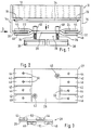
- FIG. 1 shows a side view of a height-adjustable drainage grate, in its entirety designated 10, in which a walkable web part formed here by a grating 12 is carried by a two elongated support structure 14 and 16 with an F-shaped cross section.
- the two support profiles 14 and 16 each have an upper horizontal profile section 18 or 20, the upper side of which supports the grating 12, and each have a lower horizontal profile section 22 or 24, which in one on the opposite longitudinal sides of the crossbar 26 in its entirety 28 designated sliding part provided receptacles 30 and 32 are introduced.
- Cross struts 34 and support profiles 14 and 16 thus form a stable support structure for the walkable web part 12, which - as in the exemplary embodiment shown here - can simply be inserted into the support structure, the outer vertical sections of the two support profiles 14 and 16 having an F-shaped cross section each form a lateral guide for the web part 12, but it can also be a known dirt filter made of a suitable material, for example, before inserting the web part a textile fleece.
- each threaded shaft 36 is guided in one of the threaded receptacles 40 formed here as a threaded sleeve 40 attached to the crosspiece 26 such that each foot 38 can be approximated to a greater or lesser extent to the sliding part 28 by simply rotating it.
- the sliding part 28 is shown in FIGS. 2 and 3 as viewed in the direction of arrows 2 and 3 of FIG. 1, respectively.
- each of the receptacles 30 and 32 provided on opposite longitudinal sides of the crossbar 26 is formed in that profile strips 44 and 46 formed by parallel incisions 42 in the crossbar 26 alternately upwards (profile strips 44) and downwards (profile strips 46 ) are bent off from the crosspiece 26, the free ends of the profile strips then being bent back into a position essentially parallel to the crosspiece 26.
- a threaded bore 50 is provided in each profile strip 44 and 46, through which a screw, not shown here, e.g. a grub screw can be guided so that it becomes possible to fix the sliding part 28 in a desired slide-on position relative to the support structure by tightening the screws and clamping the lower horizontal profile sections 22 and 24 of the cross-sectionally F-shaped support profiles 14 and 16.
- the thread in the bores 50 can also be omitted when using self-tapping screws.
- the sliding part can both be pushed on in such a way that the threaded sleeves 40 provided on the transverse web - as in Fig. 1 shown - point to the walkable web part 12, as well as that the threaded sleeves 40 or the like to the floor of the respective balcony, the terrace. point out so that with a single web part two different height adjustment ranges within which a height adjustment of the drainage grate is possible by turning the threaded shafts 36 of the feet 40 more or less.
- FIG. 4 shows the cross-braces 34 consisting of the two cross-sections F-shaped in cross-section and the two supporting profiles connecting these, only one of which is visible here, along with an inserted grating 12 in a perspective view.
- the two support profiles 14 and 16, which are F-shaped in cross section, are each formed in one piece in this embodiment by multiple edging of an originally flat elongated profile strip.
- each support profile 14 and 16 has a profile section 18 or 20 carrying the respective walkable web part, that is to say the grating 12 here, and a free profile section 22 or 24 such that a sliding part pushed onto the free profile sections 22 and 24 has along this profile strip can be pushed into any desired position, in which it is then fixed using the screws described, for example.
- the cross struts 34 each have only a small width in the direction of the longitudinal extension of the support profiles 14 and 16, so that they have a plurality of drainage openings 52 (of which only a few have been provided with reference numerals for reasons of clarity) on the respectively inserted one. provided web part 12 do not hinder impinging moisture.
- the cross struts 34 are connected to the horizontal profile sections 18 and 20 of the support profiles 14 and 16 by welding.
- FIG. 5 shows a possibility of constructing a walk-in web part 512 and support structure in a cost-effective one-piece manner in that the two support profiles 514 and 516, which enclose the web part 512 between them, are bent from an originally flat elongated perforated plate on opposite longitudinal sides of the perforated plate.
- the free ends of the two support profiles 514 and 516 are then again to form sliding guides for the recordings of a corresponding sliding part, for example a sliding part 28 according to FIG. 1, folded into a position parallel to the walkable web part 512 such that the free ends of the horizontal profile sections 522 and 524 thus formed point towards one another.
- This one-piece design of walkable web part 512 and support structure can - as mentioned - be done by folding over a perforated plate, that is, an already perforated plate; However, it is also possible to produce such a profile in the extrusion process and then to provide it with appropriate drainage openings or to punch drainage openings into an originally flat sheet metal blank and then to fold the metal blank several times in the manner described.
- FIG. 6 shows a support structure together with a sliding part, the two support profiles 614 and 616 each having a T-shaped cross section and being connected to one another via a number of cross struts 634, only one of which is visible here.
- the cross struts 634 each engage on the underside of a horizontal profile section 618 and 620 provided on each support profile 614 and 616, the upper side of which forms a support for a walk-in web part, not shown here, for example a grating 12 according to FIG. 1.
- the two receptacles 630 and 632 provided on opposite ends of the crossbar 626 of the sliding part 628 are opened upwards in this embodiment such that the support structure consisting of the two T-shaped support profiles 614 and 616 and the cross struts 634 are inserted into the corresponding receptacles from above can be, wherein then a vertical profile section 622 and 624 of the two cross-sectionally T-shaped support profiles 614 and 616 each engage in one of the receptacles 630 and 632.
- the receptacles are each formed by an inner profile strip 644 and an outer profile strip 646.
- Threaded bores can be made in the inner and / or the outer profile strips 644 and 646, through which holes Screws for clamping the sliding part can be inserted in a certain position relative to the support structure.
- Threaded sleeves 640 are again provided on the upper side of the crossbar 626 of the sliding part 628 facing the cross strut 634, into which corresponding threaded shafts 636 of the feet 640 engage, which can then be screwed more or less far into the threaded sleeves 640 for height adjustment.
Landscapes
- Engineering & Computer Science (AREA)
- Architecture (AREA)
- Civil Engineering (AREA)
- Structural Engineering (AREA)
- Floor Finish (AREA)
- Housing For Livestock And Birds (AREA)
- Fertilizers (AREA)
- Paper (AREA)
- Sewage (AREA)
- Road Paving Structures (AREA)
Applications Claiming Priority (2)
| Application Number | Priority Date | Filing Date | Title |
|---|---|---|---|
| DE29607127U DE29607127U1 (de) | 1996-04-19 | 1996-04-19 | Höhenverstellbarer Drainagerost |
| DE29607127U | 1996-04-19 |
Publications (3)
| Publication Number | Publication Date |
|---|---|
| EP0802287A2 true EP0802287A2 (fr) | 1997-10-22 |
| EP0802287A3 EP0802287A3 (fr) | 1998-08-19 |
| EP0802287B1 EP0802287B1 (fr) | 2002-09-04 |
Family
ID=8022827
Family Applications (1)
| Application Number | Title | Priority Date | Filing Date |
|---|---|---|---|
| EP97104958A Expired - Lifetime EP0802287B1 (fr) | 1996-04-19 | 1997-03-24 | Grille de drainage réglable en hauteur |
Country Status (3)
| Country | Link |
|---|---|
| EP (1) | EP0802287B1 (fr) |
| AT (1) | ATE223543T1 (fr) |
| DE (2) | DE29607127U1 (fr) |
Cited By (8)
| Publication number | Priority date | Publication date | Assignee | Title |
|---|---|---|---|---|
| EP1191160A1 (fr) * | 2000-09-23 | 2002-03-27 | Wilhelm Wiehe | Dispositif d'écoulement |
| EP1195476A3 (fr) * | 2000-10-04 | 2003-01-08 | Walter Gutjahr | Support réglable en hauteur pour grille de drainage |
| WO2005095725A1 (fr) * | 2004-04-01 | 2005-10-13 | Petrus Johannes Kuijper | Procede d'installation d'un systeme de conduite, systeme de conduite et element de support approprie pour la mise en oeuvre du procede |
| DE202006009404U1 (de) * | 2006-06-16 | 2007-08-23 | Sita Bauelemente Gmbh | Höhenverstellbare Entwässerungsrinne für Terrassen, Balkone u.dgl. |
| DE202010002763U1 (de) * | 2010-02-24 | 2011-07-27 | Schlüter-Systems Kg | Bodenablauf |
| CN114592576A (zh) * | 2020-12-04 | 2022-06-07 | 亚科阿尔曼欧洲两合公司 | 高度调节器 |
| AT518747A3 (de) * | 2016-05-30 | 2023-09-15 | Regenfelder Dipl Ing Jochen | Bodenablaufrinne |
| US11773580B2 (en) | 2019-12-18 | 2023-10-03 | Schluter Systems L.P. | Frame for a floor drain |
Families Citing this family (9)
| Publication number | Priority date | Publication date | Assignee | Title |
|---|---|---|---|---|
| DE29817430U1 (de) * | 1997-09-29 | 2000-02-17 | SITA-Bauelemente GmbH, 33442 Herzebrock-Clarholz | Abdeckung für Entwässerungsrinnen |
| DE20014258U1 (de) * | 2000-08-18 | 2002-01-10 | Gutjahr, Walter, 64404 Bickenbach | Entwässerungsrinne |
| FR2823777B1 (fr) * | 2001-04-24 | 2003-06-20 | Norinco | Equipement de voirie pret a l'installation, et procede d'installation correspondant |
| DE20119441U1 (de) | 2001-11-29 | 2002-04-25 | Gehring, Manfred, Dr., 72250 Freudenstadt | Entwässerungseinrichtung zur Bildung einer Rinne zwischen einer Wand und einem auf einer Schüttung verlegten Plattenbelag |
| DE20312564U1 (de) * | 2003-08-14 | 2004-12-16 | Reichlmeier Metallprofile Gmbh | Entwässerungsrinne o.dgl. |
| DE202006004904U1 (de) * | 2006-03-24 | 2007-07-26 | Reichlmeier Metallprofile Gmbh | Entwässerungsrinne für Flachdächer |
| DE202006017590U1 (de) * | 2006-11-17 | 2008-03-27 | Gutjahr, Walter | Verstellbare Drainagerost-Halterung |
| EP3216930B1 (fr) * | 2016-02-24 | 2022-11-09 | Monsun GmbH | Caniveau d'écoulement |
| CN115369985A (zh) * | 2022-09-30 | 2022-11-22 | 中国二十二冶集团有限公司 | 工业用大型地漏安装工具及安装方法 |
Family Cites Families (6)
| Publication number | Priority date | Publication date | Assignee | Title |
|---|---|---|---|---|
| DE8531810U1 (de) * | 1985-11-11 | 1986-02-27 | Kotzott, Günter, Dipl.-Ing., 4300 Essen | Sonderprofil, dessen Verschraubung und Abstützung mittels höhen-verstellbarer Stütz-Füße als Rasterrahmen-Unterkonstruktion für sogenannte Doppel- (bzw. Kabel- oder Versorgungs-) Böden |
| DE8810154U1 (de) * | 1988-08-10 | 1988-09-22 | Hauraton Betonwarenfabrik GmbH & Co KG, 7550 Rastatt | Abdeckrost für eine Entwässerungsrinne und Klemmbügel hierzu |
| DE9101016U1 (de) * | 1991-01-30 | 1991-05-23 | ACO Severin Ahlmann GmbH & Co KG, 2370 Rendsburg | Einbauhilfe |
| DE9313697U1 (de) * | 1993-09-10 | 1993-10-21 | Hauraton Betonwarenfabrik GmbH & Co KG, 76437 Rastatt | Rinnenkörper |
| DE19511206C2 (de) * | 1994-06-16 | 1999-12-30 | Ahlmann Aco Severin | Hochbauentwässerungsrinne |
| DE9411477U1 (de) * | 1994-07-15 | 1994-11-03 | Wilhelm Hafner GmbH, 78479 Reichenau | Rinne zum Verlegen in einem Fußboden |
-
1996
- 1996-04-19 DE DE29607127U patent/DE29607127U1/de not_active Expired - Lifetime
-
1997
- 1997-03-24 EP EP97104958A patent/EP0802287B1/fr not_active Expired - Lifetime
- 1997-03-24 DE DE59708098T patent/DE59708098D1/de not_active Expired - Lifetime
- 1997-03-24 AT AT97104958T patent/ATE223543T1/de active
Cited By (14)
| Publication number | Priority date | Publication date | Assignee | Title |
|---|---|---|---|---|
| EP1191160A1 (fr) * | 2000-09-23 | 2002-03-27 | Wilhelm Wiehe | Dispositif d'écoulement |
| EP1195476A3 (fr) * | 2000-10-04 | 2003-01-08 | Walter Gutjahr | Support réglable en hauteur pour grille de drainage |
| WO2005095725A1 (fr) * | 2004-04-01 | 2005-10-13 | Petrus Johannes Kuijper | Procede d'installation d'un systeme de conduite, systeme de conduite et element de support approprie pour la mise en oeuvre du procede |
| DE202006009404U1 (de) * | 2006-06-16 | 2007-08-23 | Sita Bauelemente Gmbh | Höhenverstellbare Entwässerungsrinne für Terrassen, Balkone u.dgl. |
| EP1867802A2 (fr) | 2006-06-16 | 2007-12-19 | Sita Bauelemente Gmbh | Caniveau de drainage réglable en hauteur pour terrasses, balcons et analogues |
| US9127446B2 (en) | 2010-02-24 | 2015-09-08 | Schluter Systems L.P. | Floor drain |
| DE202010002763U1 (de) * | 2010-02-24 | 2011-07-27 | Schlüter-Systems Kg | Bodenablauf |
| US9567738B2 (en) | 2010-02-24 | 2017-02-14 | Schluter Systems L.P. | Floor drain |
| AT518747A3 (de) * | 2016-05-30 | 2023-09-15 | Regenfelder Dipl Ing Jochen | Bodenablaufrinne |
| AT518747B1 (de) * | 2016-05-30 | 2024-07-15 | Regenfelder Dipl Ing Jochen | Bodenablaufrinne |
| US11773580B2 (en) | 2019-12-18 | 2023-10-03 | Schluter Systems L.P. | Frame for a floor drain |
| CN114592576A (zh) * | 2020-12-04 | 2022-06-07 | 亚科阿尔曼欧洲两合公司 | 高度调节器 |
| EP4008845A1 (fr) * | 2020-12-04 | 2022-06-08 | ACO Ahlmann SE & Co. KG | Régleur de la hauteur |
| CN114592576B (zh) * | 2020-12-04 | 2025-01-28 | 亚科阿尔曼欧洲两合公司 | 高度调节器 |
Also Published As
| Publication number | Publication date |
|---|---|
| EP0802287A3 (fr) | 1998-08-19 |
| DE29607127U1 (de) | 1997-08-21 |
| ATE223543T1 (de) | 2002-09-15 |
| DE59708098D1 (de) | 2002-10-10 |
| EP0802287B1 (fr) | 2002-09-04 |
Similar Documents
| Publication | Publication Date | Title |
|---|---|---|
| DE102007032885B4 (de) | Paneel, insbesondere Bodenpaneel und Einrichtung zum Verriegeln miteinander verbundener Paneele | |
| EP0802287B1 (fr) | Grille de drainage réglable en hauteur | |
| EP2591709B1 (fr) | Élément de sol de douche et kit de montage pour un élément de sol de douche | |
| DE19511206C2 (de) | Hochbauentwässerungsrinne | |
| DE2814713A1 (de) | Zerlegbare trennwand | |
| DE602005003313T2 (de) | Vorrichtung zum Verbinden von Rahmenteilen | |
| DE3005315A1 (de) | Befestigungsteil zur befestigung eines horizontal erstreckten tragelementes einer fassadenkonstruktion an einer senkrechten wand | |
| DE9203467U1 (de) | Bauelementsatz und daraus hergestellte Zellenanordnung | |
| EP1430579A1 (fr) | Socle pour un coffret de distribution | |
| EP0607462B1 (fr) | Faux plancher surélevé | |
| EP4166054A1 (fr) | Support de baignoire | |
| DE29516040U1 (de) | Tragstütze sowie Tragvorrichtung mit wenigstens vier im Abstand zueinander angeordneten Tragstützen | |
| DE2926780A1 (de) | Schalungssystem mit rechteckigen tafeln | |
| DE20014258U1 (de) | Entwässerungsrinne | |
| EP2425069B1 (fr) | Dispositif d'aide à la mise à niveau pour des supports en bois/en poutre, notamment de recouvrements de balcon et de terrasse | |
| DE202010000963U1 (de) | Duschablaufanordnung | |
| EP0905332B1 (fr) | Recouvrement pour caniveaux d'écoulement | |
| AT520870B1 (de) | Modulare Abdeckung für Lichtschächte, mit der Möglichkeit unterschiedliche Designs darzustellen | |
| EP3296486A1 (fr) | Ferrure d'assemblage pour l'assemblage d'éléments allongés de recouvrement | |
| EP3296475A1 (fr) | Balcon et procédé de fabrication d'un tel balcon | |
| DE9116144U1 (de) | Installationsblock | |
| DE2058167C3 (de) | Vorrichtung zum Abstützen von die äußere Schale eines zweischaligen Flachdaches bildenden Dacheindeckungsplatten | |
| DE29707906U1 (de) | Schneidvorrichtung zum Zurichten von Bodenverbundelementen | |
| DE29821761U1 (de) | Verkleidungssystem für eine Wanne, vorzugsweise Badewanne | |
| DE2153997C3 (de) | Bauelementensatz zur Montage von Verkleidungsplatten an einer Wand bzw. für eine Trennwand |
Legal Events
| Date | Code | Title | Description |
|---|---|---|---|
| PUAI | Public reference made under article 153(3) epc to a published international application that has entered the european phase |
Free format text: ORIGINAL CODE: 0009012 |
|
| AK | Designated contracting states |
Kind code of ref document: A2 Designated state(s): AT BE CH DE DK ES FR GB IT LI LU NL SE |
|
| PUAL | Search report despatched |
Free format text: ORIGINAL CODE: 0009013 |
|
| AK | Designated contracting states |
Kind code of ref document: A3 Designated state(s): AT BE CH DE DK ES FR GB IT LI LU NL SE |
|
| 17P | Request for examination filed |
Effective date: 19980909 |
|
| RAP3 | Party data changed (applicant data changed or rights of an application transferred) |
Owner name: GUTJAHR, WALTER |
|
| RIN1 | Information on inventor provided before grant (corrected) |
Inventor name: GUTJAHR, WALTER |
|
| 17Q | First examination report despatched |
Effective date: 20010921 |
|
| GRAG | Despatch of communication of intention to grant |
Free format text: ORIGINAL CODE: EPIDOS AGRA |
|
| GRAG | Despatch of communication of intention to grant |
Free format text: ORIGINAL CODE: EPIDOS AGRA |
|
| GRAH | Despatch of communication of intention to grant a patent |
Free format text: ORIGINAL CODE: EPIDOS IGRA |
|
| GRAH | Despatch of communication of intention to grant a patent |
Free format text: ORIGINAL CODE: EPIDOS IGRA |
|
| GRAA | (expected) grant |
Free format text: ORIGINAL CODE: 0009210 |
|
| AK | Designated contracting states |
Kind code of ref document: B1 Designated state(s): AT BE CH DE DK ES FR GB IT LI LU NL SE |
|
| PG25 | Lapsed in a contracting state [announced via postgrant information from national office to epo] |
Ref country code: IT Free format text: LAPSE BECAUSE OF FAILURE TO SUBMIT A TRANSLATION OF THE DESCRIPTION OR TO PAY THE FEE WITHIN THE PRESCRIBED TIME-LIMIT;WARNING: LAPSES OF ITALIAN PATENTS WITH EFFECTIVE DATE BEFORE 2007 MAY HAVE OCCURRED AT ANY TIME BEFORE 2007. THE CORRECT EFFECTIVE DATE MAY BE DIFFERENT FROM THE ONE RECORDED. Effective date: 20020904 |
|
| REF | Corresponds to: |
Ref document number: 223543 Country of ref document: AT Date of ref document: 20020915 Kind code of ref document: T |
|
| REG | Reference to a national code |
Ref country code: GB Ref legal event code: FG4D Free format text: NOT ENGLISH |
|
| REG | Reference to a national code |
Ref country code: CH Ref legal event code: EP |
|
| GBT | Gb: translation of ep patent filed (gb section 77(6)(a)/1977) |
Effective date: 20020904 |
|
| REF | Corresponds to: |
Ref document number: 59708098 Country of ref document: DE Date of ref document: 20021010 |
|
| PG25 | Lapsed in a contracting state [announced via postgrant information from national office to epo] |
Ref country code: DK Free format text: LAPSE BECAUSE OF FAILURE TO SUBMIT A TRANSLATION OF THE DESCRIPTION OR TO PAY THE FEE WITHIN THE PRESCRIBED TIME-LIMIT Effective date: 20021204 |
|
| PGFP | Annual fee paid to national office [announced via postgrant information from national office to epo] |
Ref country code: SE Payment date: 20030225 Year of fee payment: 7 |
|
| PGFP | Annual fee paid to national office [announced via postgrant information from national office to epo] |
Ref country code: BE Payment date: 20030312 Year of fee payment: 7 |
|
| PGFP | Annual fee paid to national office [announced via postgrant information from national office to epo] |
Ref country code: GB Payment date: 20030319 Year of fee payment: 7 |
|
| PG25 | Lapsed in a contracting state [announced via postgrant information from national office to epo] |
Ref country code: LU Free format text: LAPSE BECAUSE OF NON-PAYMENT OF DUE FEES Effective date: 20030324 |
|
| PGFP | Annual fee paid to national office [announced via postgrant information from national office to epo] |
Ref country code: FR Payment date: 20030326 Year of fee payment: 7 |
|
| ET | Fr: translation filed | ||
| PG25 | Lapsed in a contracting state [announced via postgrant information from national office to epo] |
Ref country code: ES Free format text: LAPSE BECAUSE OF FAILURE TO SUBMIT A TRANSLATION OF THE DESCRIPTION OR TO PAY THE FEE WITHIN THE PRESCRIBED TIME-LIMIT Effective date: 20030328 |
|
| REG | Reference to a national code |
Ref country code: CH Ref legal event code: NV Representative=s name: BOVARD AG PATENTANWAELTE |
|
| PLBE | No opposition filed within time limit |
Free format text: ORIGINAL CODE: 0009261 |
|
| STAA | Information on the status of an ep patent application or granted ep patent |
Free format text: STATUS: NO OPPOSITION FILED WITHIN TIME LIMIT |
|
| 26N | No opposition filed |
Effective date: 20030605 |
|
| PG25 | Lapsed in a contracting state [announced via postgrant information from national office to epo] |
Ref country code: GB Free format text: LAPSE BECAUSE OF NON-PAYMENT OF DUE FEES Effective date: 20040324 |
|
| PG25 | Lapsed in a contracting state [announced via postgrant information from national office to epo] |
Ref country code: SE Free format text: LAPSE BECAUSE OF NON-PAYMENT OF DUE FEES Effective date: 20040325 |
|
| PG25 | Lapsed in a contracting state [announced via postgrant information from national office to epo] |
Ref country code: BE Free format text: LAPSE BECAUSE OF NON-PAYMENT OF DUE FEES Effective date: 20040331 |
|
| BERE | Be: lapsed |
Owner name: *GUTJAHR WALTER Effective date: 20040331 |
|
| EUG | Se: european patent has lapsed | ||
| GBPC | Gb: european patent ceased through non-payment of renewal fee |
Effective date: 20040324 |
|
| PG25 | Lapsed in a contracting state [announced via postgrant information from national office to epo] |
Ref country code: FR Free format text: LAPSE BECAUSE OF NON-PAYMENT OF DUE FEES Effective date: 20041130 |
|
| REG | Reference to a national code |
Ref country code: FR Ref legal event code: ST |
|
| REG | Reference to a national code |
Ref country code: CH Ref legal event code: PFA Owner name: GUTJAHR, WALTER Free format text: GUTJAHR, WALTER#ERNST-LUDWIG-WEG 29#64404 BICKENBACH (DE) -TRANSFER TO- GUTJAHR, WALTER#ERNST-LUDWIG-WEG 29#64404 BICKENBACH (DE) |
|
| PGFP | Annual fee paid to national office [announced via postgrant information from national office to epo] |
Ref country code: NL Payment date: 20150323 Year of fee payment: 19 |
|
| REG | Reference to a national code |
Ref country code: CH Ref legal event code: PUE Owner name: ARDEX ANLAGEN GMBH, DE Free format text: FORMER OWNER: GUTJAHR, WALTER, DE |
|
| REG | Reference to a national code |
Ref country code: DE Ref legal event code: R082 Ref document number: 59708098 Country of ref document: DE Representative=s name: PATENTANWAELTE KATSCHER HABERMANN, DE Ref country code: DE Ref legal event code: R081 Ref document number: 59708098 Country of ref document: DE Owner name: ARDEX ANLAGEN GMBH, DE Free format text: FORMER OWNER: GUTJAHR, WALTER, 64404 BICKENBACH, DE |
|
| REG | Reference to a national code |
Ref country code: NL Ref legal event code: PD Owner name: ARDEX ANLAGEN GMBH; DE Free format text: DETAILS ASSIGNMENT: VERANDERING VAN EIGENAAR(S), OVERDRACHT; FORMER OWNER NAME: WALTER GUTJAHR Effective date: 20151022 |
|
| PGFP | Annual fee paid to national office [announced via postgrant information from national office to epo] |
Ref country code: DE Payment date: 20160208 Year of fee payment: 20 Ref country code: CH Payment date: 20160322 Year of fee payment: 20 |
|
| PGFP | Annual fee paid to national office [announced via postgrant information from national office to epo] |
Ref country code: AT Payment date: 20160318 Year of fee payment: 20 |
|
| REG | Reference to a national code |
Ref country code: NL Ref legal event code: MM Effective date: 20160401 |
|
| PG25 | Lapsed in a contracting state [announced via postgrant information from national office to epo] |
Ref country code: NL Free format text: LAPSE BECAUSE OF NON-PAYMENT OF DUE FEES Effective date: 20160401 |
|
| REG | Reference to a national code |
Ref country code: AT Ref legal event code: PC Ref document number: 223543 Country of ref document: AT Kind code of ref document: T Owner name: ARDEX ANLAGEN GMBH, DE Effective date: 20170202 |
|
| REG | Reference to a national code |
Ref country code: DE Ref legal event code: R071 Ref document number: 59708098 Country of ref document: DE |
|
| REG | Reference to a national code |
Ref country code: CH Ref legal event code: PL |
|
| REG | Reference to a national code |
Ref country code: AT Ref legal event code: MK07 Ref document number: 223543 Country of ref document: AT Kind code of ref document: T Effective date: 20170324 |