EP0802273B1 - Wäschetrockner - Google Patents
Wäschetrockner Download PDFInfo
- Publication number
- EP0802273B1 EP0802273B1 EP97103521A EP97103521A EP0802273B1 EP 0802273 B1 EP0802273 B1 EP 0802273B1 EP 97103521 A EP97103521 A EP 97103521A EP 97103521 A EP97103521 A EP 97103521A EP 0802273 B1 EP0802273 B1 EP 0802273B1
- Authority
- EP
- European Patent Office
- Prior art keywords
- hollow axle
- bearing
- roller
- engagement
- washing dryer
- Prior art date
- Legal status (The legal status is an assumption and is not a legal conclusion. Google has not performed a legal analysis and makes no representation as to the accuracy of the status listed.)
- Expired - Lifetime
Links
- 238000005406 washing Methods 0.000 title claims description 14
- 229920006395 saturated elastomer Polymers 0.000 claims description 6
- 238000002347 injection Methods 0.000 claims description 3
- 239000007924 injection Substances 0.000 claims description 3
- 239000004033 plastic Substances 0.000 claims description 3
- 229920003023 plastic Polymers 0.000 claims description 3
- 238000005461 lubrication Methods 0.000 description 5
- 239000002245 particle Substances 0.000 description 3
- 238000004519 manufacturing process Methods 0.000 description 2
- 238000000034 method Methods 0.000 description 2
- 208000027418 Wounds and injury Diseases 0.000 description 1
- 230000006378 damage Effects 0.000 description 1
- 229920001971 elastomer Polymers 0.000 description 1
- 208000014674 injury Diseases 0.000 description 1
- 230000001050 lubricating effect Effects 0.000 description 1
- 230000000149 penetrating effect Effects 0.000 description 1
Images

Classifications
-
- D—TEXTILES; PAPER
- D06—TREATMENT OF TEXTILES OR THE LIKE; LAUNDERING; FLEXIBLE MATERIALS NOT OTHERWISE PROVIDED FOR
- D06F—LAUNDERING, DRYING, IRONING, PRESSING OR FOLDING TEXTILE ARTICLES
- D06F58/00—Domestic laundry dryers
- D06F58/02—Domestic laundry dryers having dryer drums rotating about a horizontal axis
- D06F58/04—Details
- D06F58/06—Mountings for the rotating drums
Definitions
- the invention relates to a washing dryer with a drum which is rotatably mounted and which may be rotated, which is additionally guided in the vicinity of the intake side by means of rollers which are supported on the drum shell and which are rotatably mounted by means of bearing axes in a casing portion surrounding the intake opening.
- a washing treatment machine of this type is known from CH-PS 429 644 and US-A-4 754 556.
- this known washing treatment machines the bearing and lubrication of the roller presents considerable difficulty.
- the bearing axis in the form of a rotary part, is extremely expensive to manufacture and requires a considerable outlay on assembly for securing the bearing axis on the casing portion and for securing the roller axially on the bearing axis.
- the purpose of the invention in a washing dryer of the type already mentioned, is to improve the bearing for the roller supporting the drum on the intake side in such a way that simple assembly and a type of permanent lubrication of the bearing is achieved with simple parts.
- the bearing axle is in the form of a hollow axle which is C-shaped in cross-section, and into which there is inserted in the vicinity of the bearing bore of the roller an oil-saturated felt block, in that the felt block projects out of the hollow axle and is resiliently supported on the bearing bore of the roller, in that the roller is positioned axially on the hollow axle by means of two securing members, and in that the securing members are provided with retaining projections, which project through apertures in the hollow axle, into said axle, and axially secure the felt block.
- the roller may be axially positioned on the hollow axle by means of two securing members.
- the oil-saturated felt block inserted into the hollow axle is at the same time axially secured, so that it retains its position relative to the bearing bore of the roller and permanently lubricates it.
- the elastic property of the felt block is utilised in such a way that a compensation for tolerance takes place.
- the felt block prevents dirt particles from penetrating into the bearing and can also bind said particles. In this way a type of permanent lubrication is achieved.
- the securing members are arcuate in form and provided on the inner sides facing one another of their legs with engagement projections, which engage resiliently in engagement apertures facing one another of the hollow axle, so that they may be rapidly and simply engaged on the hollow axle.
- the retaining projection is introduced into the hollow axle and secures the felt block axially.
- the securing members abut closely against the outer contour of the hollow axle.
- the retaining projections and engagement projections of these securing members, as well as the apertures and the engagement apertures of the hollow axle have rectangular cross-sections co-ordinated with one another.
- the free longitudinal edges of the hollow axle merge into edges aligned towards one another and lying in one plane, then sharp edges entailing a risk of injury during assembly are avoided.
- these edges reinforce the hollow axle and also the hollow axle may be non-rotatably secured in a receiving means of a bearing bush adapted to the non-round outer contour.
- the hollow axle and the securing members extend over an angular range of more than 180°.
- the hollow axle in order to secure the hollow axle on the casing portion, is provided on the end facing away from the roller with engagement apertures into which engagement members of a bearing bush, accommodating the hollow axle, of a bearing flange of the casing portion resiliently engage.
- the securing member with the retaining projection and the engagement projections, is formed as a one-piece plastics injection moulded part, while the hollow axle with all its members is produced as a hardened stamped and shaped part.
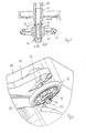
- FIG. 1 shows, there is located on the intake side of the drum 10 a casing portion 11, which in a known way is used for articulating the doors and for inserting a lint screen. In addition, it has a portion of the air duct for the process air circuit.
- the present case involves the rotary bearing or roller 15, which is supported on a running surface 14 on the shell surface of the drum 10.
- the roller 15 is mounted on a bearing flange 12 of the casing portion 11, which surrounds the intake opening of the drum 10.
- the bearing of the drum 10 on the opposite end face and the drive means for its rotary movement are not shown in Figure 1, as they are of no importance for the present invention.
- the roller 15 carries a rubber tyre 16 and is supported thereby on the running surface 14 of the drum shell.
- the bearing flange 12 is integrally moulded on the casing portion 11 and has a bearing bush 13, into which the bearing axle of the roller is inserted.
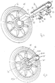
- the bearing axle for the roller 15 is in the form of a hollow axle 20 with a C-shaped cross-section.
- the hollow axle 20 is provided with rims 21 and 22 aligned towards one another and lying in one plane.
- pairs of mutually-opposed engagement apertures 23 and 24 are provided in the hollow axis, and which for example have a rectangular cross-section.
- a securing member 30 may be resiliently engaged with engagement projections 31 on the inner sides of its legs into the engagement apertures 23 and 24.
- the retaining projection 32 of the securing member 30 is introduced into the hollow axle 20 through the aperture 26 and serves as a stop for the felt block 40.
- the hollow axle with the inwardly-rounded rims 21 and 22 has a non-rounded outer contour. If the bearing bush 13 of the bearing flange 12 is adapted with the receiving means to this non-rounded contour of the hollow axle 20, then the introduced hollow axle 20 is non-rotatably secured in the bearing bush 13.
- the end of the hollow axle 20 is thrust into the bearing bore 17 of the roller 15.
- the end of the hollow axle 20 projecting on the opposite side out of the bearing bore 17 is positioned in the other axial direction with the second securing member 30.
- the engagement projections 31 engage in the engagement apertures 23 of the hollow axle 20, and the retaining projection 32 of the securing member 30, after passing through an aperture 26 in the hollow axle 20, secures the felt block 40 in the other axial direction.
- the oil-saturated felt block 40 projects out of the hollow axle 20 and is resiliently supported on the bearing bore 17 of the roller 15, as can be seen from the assembled condition of roller 15 and hollow axle 20 shown in Figure 4.
- the hollow axle 20 On its free end, the hollow axle 20 carries a further pair of engagement apertures 25, into which engagement members 18 of the bearing bush 13 engage, when the hollow axle 20 is introduced with the roller 15 in the correct angular position, as the cross-section in Figure 5 shows.
- the roller 15 is clearly axially positioned between the two securing members 30 and the retaining projections 32 of the same secure the felt block 40 in such a way that it lies permanently in the bearing bore 17 of the roller 15.
- the securing members 13 in the central region are reinforced with the retaining projection 32 as an axial stop 33; they are arcuate in shape, so that they abut closely on the periphery of the hollow axle 20.
- the hollow axle 20 and the securing member 30 extend over an angular range of more than 180°, yet leave a sufficiently wide slot for the introduction of the felt block 40.
- the engagement projections 31 and the retaining projections 32 are rectangular in cross-section, and co-ordinated with the engagement apertures 22 and 23 and the apertures 26 in the hollow axle 20, so that clear resilient engagement and a good hold of the securing members 30 on the hollow axle 20 is achieved.
- the securing member 30, with the engagement projections 31, the retaining projection 32 and the axial stop 33 are produced as a one-piece plastics injection moulded part.
- the hollow axle 20 is formed from a hardened stamped and shaped part.
- the oil-saturated felt block 40 provides a type of permanent lubrication for the bearing of the roller 15 on the hollow axle 20.
- the felt block 40 also keeps dirt particles away from the bearing, and can also bind them.
Landscapes
- Engineering & Computer Science (AREA)
- Textile Engineering (AREA)
- Rolls And Other Rotary Bodies (AREA)
- Support Of The Bearing (AREA)
- Main Body Construction Of Washing Machines And Laundry Dryers (AREA)
- General Details Of Gearings (AREA)
Claims (8)
- Wäschetrockner mit einer Trommel, die drehbar befestigt ist, sich drehen kann und zusätzlich in der Nähe der Wäscheeingabeseite mittels Rollen (15) geführt wird, die sich auf der Trommelschale (10) abstützen und auf Lagerachsen drehbar befestigt sind, die an einem die Wäsche-eingabeöffnung umgebenden Gehäuseteil (11) festgelegt sind,
dadurch gekennzeichnet, dassdie Lagerachse die Form einer Hohlachse (20) hat, die im Querschnitt C-förmig ausgebildet ist und in die in der Nähe der Lagerbohrung (17) der Rolle (15) ein ölgesättigter Filzblock (40) eingefügt ist,der Filzblock (40) aus der Hohlachse (20) herausragt und sich an der Lagerbohrung (17) der Rolle (15) federnd abstützt,die Rolle (15) auf der Hohlachse (20) mittels zweier Sicherungsglieder (30) axial positioniert ist unddie Sicherungsglieder (30) mit Rückhaltevorsprüngen (32) versehen sind, die durch Öffnungen (26) in der Hohlachse (20) in diese Hohlachse ragen und den Filzblock (40) axial sichern. - Wäschetrockner nach Anspruch 1,
dadurch gekennzeichnet, dass die Sicherungsglieder (30) bogenförmig ausgebildet und auf den einander zugewandten Innenseiten ihrer Beine mit Eingriffsvorsprüngen (31) versehen sind, die in gegenüberliegende Eingriffsöffnungen (23 oder 24) der Hohlachse (20) federnd eingreifen. - Wäschetrockner nach Anspruch 1 oder 2,
dadurch gekennzeichnet, dass die Rückhaltevorsprünge (32) und die Eingriffsvorsprünge (31) der Sicherungsglieder (30) sowie die Öffnungen (26) und Eingriffsöffnungen (23, 24) der Hohlachse (20) rechteckförmige Querschnitte aufweisen, die miteinander koordiniert sind. - Wäschetrockner nach einem der Ansprüche 1 bis 3,
dadurch gekennzeichnet, dass die freien Längskanten der Hohlachse (20) abgebogene Randstreifen (21, 22) aufweisen, die aufeinander ausgerichtet sind und in einer gemeinsamen Ebene liegen, und dass die Hohlachse (20) mit ihrer unrunden Außenkontur in einer Lagerbuchse (13) unverdrehbar gesichert ist, die mit einer an die unrunde Außenkontur angepassten Öffnung versehen ist. - Wäschetrockner nach einem der Ansprüche 1 bis 4,
dadurch gekennzeichnet, dass die Hohlachse (20) und die Sicherungsglieder (30) über einen Winkelbereich von mehr als 180° verlaufen. - Wäschetrockner nach einem der Ansprüche 1 bis 5,
dadurch gekennzeichnet, dass die Hohlachse (20) am rollenfernen Ende mit Eingriffsöffnungen (25) versehen ist, in die Eingriffsglieder (18) einer Lagerbuchse (13) federnd eingreifen, die die Hohlachse (20) an einem Lagerflansch (12) des Ghäuseteils (11) festlegt. - Wäschetrockner nach einem der Ansprüche 1 bis 6,
dadurch gekennzeichnet, dass das Sicherungsglied (30) mit dem Rückhaltevorsprung (32) und dem Eingriffsvorsprung (31) einstückig als Kunststoffspritzteil hergestellt ist. - Wäschetrockner nach einem der Ansprüche 1 bis 7,
dadurch gekennzeichnet, dass die Hohlachse (20) die Form eines gehärteten, gestanzten und geformten Teils hat.
Applications Claiming Priority (2)
| Application Number | Priority Date | Filing Date | Title |
|---|---|---|---|
| DE19615822 | 1996-04-20 | ||
| DE19615822A DE19615822C1 (de) | 1996-04-20 | 1996-04-20 | Wäschetrockner |
Publications (3)
| Publication Number | Publication Date |
|---|---|
| EP0802273A2 EP0802273A2 (de) | 1997-10-22 |
| EP0802273A3 EP0802273A3 (de) | 1998-07-08 |
| EP0802273B1 true EP0802273B1 (de) | 2002-06-05 |
Family
ID=7791965
Family Applications (1)
| Application Number | Title | Priority Date | Filing Date |
|---|---|---|---|
| EP97103521A Expired - Lifetime EP0802273B1 (de) | 1996-04-20 | 1997-03-04 | Wäschetrockner |
Country Status (2)
| Country | Link |
|---|---|
| EP (1) | EP0802273B1 (de) |
| DE (2) | DE19615822C1 (de) |
Families Citing this family (9)
| Publication number | Priority date | Publication date | Assignee | Title |
|---|---|---|---|---|
| DE10253113A1 (de) * | 2002-11-13 | 2004-05-27 | Herbert Kannegiesser Gmbh | Trockner, insbesondere Wäschetrockner |
| US7140123B2 (en) * | 2003-11-07 | 2006-11-28 | Samsung Electronics Co., Ltd. | Roller and clothes drying apparatus provided with the same |
| EP1541742B1 (de) * | 2003-12-12 | 2007-10-03 | Miele & Cie. KG | Wäschetrockner mit einer Rollenlagerung |
| EP2476795B1 (de) * | 2008-03-19 | 2019-10-30 | Electrolux Home Products Corporation N.V. | Wäschetrockner |
| WO2009132969A1 (en) * | 2008-05-02 | 2009-11-05 | Arcelik Anonim Sirketi | A dryer |
| WO2010076128A1 (en) * | 2008-12-29 | 2010-07-08 | Arcelik Anonim Sirketi | A dryer comprising a drum the front bearing of which is performed by rollers |
| EP2379795B1 (de) * | 2008-12-30 | 2012-11-28 | Arçelik Anonim Sirketi | Hilfsrolle für trocknertrommel |
| IT1396409B1 (it) * | 2009-10-30 | 2012-11-19 | Indesit Co Spa | Macchina per l'asciugatura di panni. |
| US8756829B2 (en) | 2010-06-09 | 2014-06-24 | Whirlpool Corporation | Roller assembly for a laundry treating appliance |
Family Cites Families (5)
| Publication number | Priority date | Publication date | Assignee | Title |
|---|---|---|---|---|
| US2769246A (en) * | 1953-05-06 | 1956-11-06 | Murray Corp | Clothes drier |
| US2823962A (en) * | 1957-04-19 | 1958-02-18 | Gen Electric | Bearing assembly and clothes dryer equipped therewith |
| CH429644A (de) * | 1962-02-01 | 1967-02-15 | Siemens Elektrogeraete Gmbh | Nach dem Trommelprinzip arbeitende Wäschebehandlungsmaschine |
| US3947076A (en) * | 1974-12-19 | 1976-03-30 | Illinois Tool Works Inc. | Lubricating bearing and bracket mounting |
| US4754556A (en) * | 1986-08-18 | 1988-07-05 | Whirlpool Corporation | Front bulkhead mounting for a dryer |
-
1996
- 1996-04-20 DE DE19615822A patent/DE19615822C1/de not_active Expired - Fee Related
-
1997
- 1997-03-04 EP EP97103521A patent/EP0802273B1/de not_active Expired - Lifetime
- 1997-03-04 DE DE69712974T patent/DE69712974T2/de not_active Expired - Fee Related
Also Published As
| Publication number | Publication date |
|---|---|
| EP0802273A2 (de) | 1997-10-22 |
| DE69712974D1 (de) | 2002-07-11 |
| EP0802273A3 (de) | 1998-07-08 |
| DE69712974T2 (de) | 2002-11-07 |
| DE19615822C1 (de) | 1997-05-07 |
Similar Documents
| Publication | Publication Date | Title |
|---|---|---|
| EP0802273A2 (de) | Wäschetrockner | |
| US4713739A (en) | Clam shell gear box housing and retainer | |
| JP2932041B2 (ja) | ブッシュ | |
| CN203554166U (zh) | 用于机器的电机 | |
| US6427287B1 (en) | Door stop which is integrated with a door hinge | |
| DE102017103936A1 (de) | Rotor mit einem Lager | |
| US6901634B2 (en) | Door check device with insert molded roller | |
| KR100463320B1 (ko) | 와이퍼블레이드와그제조방법 | |
| EP0708879A1 (de) | Kipphebel | |
| US5207771A (en) | Radial plunger type pump with counter weight and washer integrally secured | |
| KR100645185B1 (ko) | 회전형 칸막이가 구비된 차량용 글로브 박스 | |
| EP3862480B1 (de) | Motorhaltevorrichtung für einen motor eines haushaltsgeräts | |
| CA1289013C (en) | Combined normal and fine sowing wheel for sowing machines | |
| KR0134678Y1 (ko) | 샤프트 고정장치 | |
| GB2226090A (en) | Bearing assembly for electric motor | |
| KR200173303Y1 (ko) | 창문용 호차바퀴 | |
| JPH04244618A (ja) | 双方向回転を制限する装置 | |
| KR100518022B1 (ko) | 전동기용 엔드 브래킷의 마운트 링 체결구조 | |
| CN222909772U (zh) | 一种汽车扶手箱阻尼器安装结构 | |
| DE4026549C2 (de) | Von vorn beschickbare Waschmaschine | |
| KR860000488Y1 (ko) | 전화기의 후크 스위치용 플런저 고정장치 | |
| JPH0134034Y2 (de) | ||
| KR200147329Y1 (ko) | 자동차의 에어밴트 조립체 | |
| KR0116851Y1 (ko) | 압입부쉬류 탈거기구 | |
| JPS61260181A (ja) | 回り止めピンを有する回転軸の支持板への組込み方法 |
Legal Events
| Date | Code | Title | Description |
|---|---|---|---|
| PUAI | Public reference made under article 153(3) epc to a published international application that has entered the european phase |
Free format text: ORIGINAL CODE: 0009012 |
|
| AK | Designated contracting states |
Kind code of ref document: A2 Designated state(s): DE FR GB IT SE |
|
| PUAL | Search report despatched |
Free format text: ORIGINAL CODE: 0009013 |
|
| AK | Designated contracting states |
Kind code of ref document: A3 Designated state(s): DE FR GB IT SE |
|
| 17P | Request for examination filed |
Effective date: 19981221 |
|
| GRAG | Despatch of communication of intention to grant |
Free format text: ORIGINAL CODE: EPIDOS AGRA |
|
| 17Q | First examination report despatched |
Effective date: 20010808 |
|
| GRAG | Despatch of communication of intention to grant |
Free format text: ORIGINAL CODE: EPIDOS AGRA |
|
| GRAH | Despatch of communication of intention to grant a patent |
Free format text: ORIGINAL CODE: EPIDOS IGRA |
|
| GRAH | Despatch of communication of intention to grant a patent |
Free format text: ORIGINAL CODE: EPIDOS IGRA |
|
| GRAA | (expected) grant |
Free format text: ORIGINAL CODE: 0009210 |
|
| AK | Designated contracting states |
Kind code of ref document: B1 Designated state(s): DE FR GB IT SE |
|
| REG | Reference to a national code |
Ref country code: GB Ref legal event code: FG4D |
|
| REF | Corresponds to: |
Ref document number: 69712974 Country of ref document: DE Date of ref document: 20020711 |
|
| ET | Fr: translation filed | ||
| PLBE | No opposition filed within time limit |
Free format text: ORIGINAL CODE: 0009261 |
|
| STAA | Information on the status of an ep patent application or granted ep patent |
Free format text: STATUS: NO OPPOSITION FILED WITHIN TIME LIMIT |
|
| 26N | No opposition filed |
Effective date: 20030306 |
|
| PGFP | Annual fee paid to national office [announced via postgrant information from national office to epo] |
Ref country code: SE Payment date: 20090327 Year of fee payment: 13 Ref country code: IT Payment date: 20090330 Year of fee payment: 13 Ref country code: DE Payment date: 20090327 Year of fee payment: 13 |
|
| PGFP | Annual fee paid to national office [announced via postgrant information from national office to epo] |
Ref country code: FR Payment date: 20090317 Year of fee payment: 13 |
|
| PGFP | Annual fee paid to national office [announced via postgrant information from national office to epo] |
Ref country code: GB Payment date: 20090403 Year of fee payment: 13 |
|
| EUG | Se: european patent has lapsed | ||
| GBPC | Gb: european patent ceased through non-payment of renewal fee |
Effective date: 20100304 |
|
| REG | Reference to a national code |
Ref country code: FR Ref legal event code: ST Effective date: 20101130 |
|
| PG25 | Lapsed in a contracting state [announced via postgrant information from national office to epo] |
Ref country code: FR Free format text: LAPSE BECAUSE OF NON-PAYMENT OF DUE FEES Effective date: 20100331 |
|
| PG25 | Lapsed in a contracting state [announced via postgrant information from national office to epo] |
Ref country code: DE Free format text: LAPSE BECAUSE OF NON-PAYMENT OF DUE FEES Effective date: 20101001 |
|
| PG25 | Lapsed in a contracting state [announced via postgrant information from national office to epo] |
Ref country code: GB Free format text: LAPSE BECAUSE OF NON-PAYMENT OF DUE FEES Effective date: 20100304 Ref country code: IT Free format text: LAPSE BECAUSE OF NON-PAYMENT OF DUE FEES Effective date: 20100304 |
|
| PG25 | Lapsed in a contracting state [announced via postgrant information from national office to epo] |
Ref country code: SE Free format text: LAPSE BECAUSE OF NON-PAYMENT OF DUE FEES Effective date: 20100305 |