EP0802083A2 - Rétroviseur extérieur - Google Patents
Rétroviseur extérieur Download PDFInfo
- Publication number
- EP0802083A2 EP0802083A2 EP97104127A EP97104127A EP0802083A2 EP 0802083 A2 EP0802083 A2 EP 0802083A2 EP 97104127 A EP97104127 A EP 97104127A EP 97104127 A EP97104127 A EP 97104127A EP 0802083 A2 EP0802083 A2 EP 0802083A2
- Authority
- EP
- European Patent Office
- Prior art keywords
- mirror
- mirror housing
- base
- housing
- adjusting
- Prior art date
- Legal status (The legal status is an assumption and is not a legal conclusion. Google has not performed a legal analysis and makes no representation as to the accuracy of the status listed.)
- Withdrawn
Links
Images


Classifications
-
- B—PERFORMING OPERATIONS; TRANSPORTING
- B60—VEHICLES IN GENERAL
- B60R—VEHICLES, VEHICLE FITTINGS, OR VEHICLE PARTS, NOT OTHERWISE PROVIDED FOR
- B60R1/00—Optical viewing arrangements; Real-time viewing arrangements for drivers or passengers using optical image capturing systems, e.g. cameras or video systems specially adapted for use in or on vehicles
- B60R1/02—Rear-view mirror arrangements
- B60R1/06—Rear-view mirror arrangements mounted on vehicle exterior
- B60R1/062—Rear-view mirror arrangements mounted on vehicle exterior with remote control for adjusting position
- B60R1/064—Rear-view mirror arrangements mounted on vehicle exterior with remote control for adjusting position by manually powered actuators
- B60R1/066—Rear-view mirror arrangements mounted on vehicle exterior with remote control for adjusting position by manually powered actuators for adjusting the mirror relative to its housing
Definitions
- the invention relates to an exterior rearview mirror for vehicles, preferably for motor vehicles, according to the preamble of claim 1.
- the invention has for its object to design the generic external rearview mirror so that with a simple construction of the adjustment device ensures that the mirror glass support plate after the mirror housing has been folded down and returned to the position of use resumes its originally set position.
- the adjustment device does not snap out of the mirror glass carrier plate when the mirror housing is folded down, but remains connected to it.
- the two control parts of the adjustment device are pivoted against each other when the mirror housing folds down relative to the mirror base. This ensures that the mirror glass support plate maintains its set position with respect to the mirror housing when folded down and folded back into the position of use.
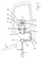
- the exterior rearview mirror can be attached in a known manner to the right and to the left outside of the motor vehicle. It has a mirror base 1, which has a transversely projecting support part 2, on which a mirror housing 3 is pivotally mounted about an upright axis in a manner to be described.
- a carrier plate 4 (FIG. 4) is adjustable in a known manner stored on which a mirror glass 5 is attached. As shown in FIG. 4, the carrier plate 4 is supported in the mirror housing 3 with a ball joint and can be adjusted to the desired position from the interior of the vehicle using an adjusting device 6.
- An adjusting lever 7 protrudes into the interior of the motor vehicle through the mirror base 1 and is mounted in the mirror base 1 by means of a ball 8 in a known manner. Via the ball 8, the adjusting lever 7 is rigidly connected to a U-shaped bracket 9, the leg 10 adjoining the ball 8 lying inside the mirror base 1. The other leg 11 of the bracket 9 protrudes into the mirror housing 3. Both legs 10, 11 are connected to one another by a web 12 which is arranged within the support part 2 of the mirror base 1. On the free end of the leg 11, an intermediate lever 13 is pivotally mounted, which has an axis 14 approximately in half length, which in the position of use of the exterior rearview mirror projects upwards and downwards over the intermediate lever 13.
- This axis 14 which is upright in the position of use of the exterior rear view mirror, protrude into elongated holes 15 and 16 which are provided in legs 17 and 18 of a U-shaped support 19.
- the intermediate lever 13 projects between the two mutually parallel legs 17, 18 of the carrier 19, which is firmly connected to the mirror housing 3.
- the legs 17, 18 extend in the direction of the mirror base 3 and lie at a small acute angle to the rear 20 of the mirror housing 3 (FIG. 4).
- the elongated holes 15, 16 are provided near the free ends of the legs 17, 18 and extend in the longitudinal direction thereof.
- the width of the elongated holes 15, 16 corresponds to the diameter of the axis 14.
- the intermediate lever 13 is provided on its side facing away from the mirror base 1 with a peg-shaped extension 21 which has a ball 22 at the free end.
- the bearing part 23 is spaced from a bearing ball 24, which is provided centrally on the rear of the mirror glass support plate 4.
- the bearing ball 24 is received in a known manner in a bearing receptacle 25 (FIG. 4) which is provided in the mirror housing 3.
- the adjusting lever 7 and the bracket 9 of the adjusting device 6 lie in a common, upright plane.
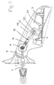
- the bracket 9 is pivoted upwards. Since the intermediate lever 13 is axially fixed on the leg 11 of the bracket 9, the intermediate lever 13 is taken accordingly.
- the ball 22 is positively connected to the bearing part 23. Since the ball 22 is rigidly connected to the intermediate lever 13 via the extension 21, the mirror glass carrier plate 4 is pivoted accordingly in this way via the bearing part 23. Since the axis 14 projects through the elongated holes 15, 16, the axis can be moved within the elongated holes 15, 16 during the described adjustment movement, so that the described adjustment process is made possible.
- the intermediate lever 13 lies obliquely with respect to the legs 17, 18 of the carrier 19.
- control lever 7 can also be pivoted in the reverse direction by means of the bearing ball 8 in the position shown in dashed lines in a clockwise direction.
- the bracket 9, the intermediate lever 13 and the carrier plate 4 are adjusted accordingly.
- a cover part 26 is seated on the free end of the lever 7, so that the user of the adjusting device 6 can reliably actuate the adjusting lever 7.
- control lever 7 has been pivoted in the vertical direction. Due to the ball-and-socket mounting by means of the bearing ball 8, the adjusting lever 7 can of course be pivoted in any direction in order to adjust the carrier plate 4 to the required position.
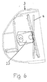
- Fig. 5 shows the possibility of adjusting the lever 7, for example, in the horizontal direction. If the actuating lever 7 is pivoted clockwise from the position shown with solid lines into the position shown with dashed lines, the intermediate lever 13 is pivoted counterclockwise. In this case, the axis 14 of the intermediate lever 13 does not move in the elongated holes of the carrier 19, but rotates about its axis in the elongated holes. About the neck 21 and the ball 22 of the intermediate lever 13, the mirror glass support plate 4 is pivoted about its spherical bearing 24 also clockwise. In this case, the carrier plate 4 is adjusted about an imaginary vertical axis.
- the mirror housing 3 can fold down relative to the mirror base 1 in the event of a stroke in and against the direction of travel.
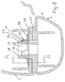
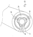
- a bearing part 27 is accommodated in the support part 2 of the mirror base 1, which has an upward-looking, sleeve-shaped extension 28 projecting upwards above the support part 2. It is provided at the free end with at least one undercut 29 on the outside (FIG. 8).
- three undercuts 29 are provided, which are preferably arranged uniformly distributed over the circumference of the extension 28.
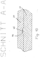
- three radial projections 30 to 32 are provided at a distance from one another at the free end of the projection 28 (FIG. 12), each of which has a surface 33 to 35 lying on a conical surface.
- the spring washer 37 has a conical base body 38, the peripheral edge of which rests on a supporting part 39 of the mirror housing 3. He sits on the bearing part 27 of the mirror base 1.
- the base body 38 of the spring washer 37 tapers in the direction of the free end of the shoulder 28 of the bearing part 27. From the base body 38, three tabs 40 to 42 are preferably distributed obliquely upward over the circumference, with their free ends on the undersides 36 approaches 30 to 32 come into contact.
- the base body 38 and the tabs 40 to 42 of the spring washer 37 are designed such that the spring washer 37 is elastically prestressed in the assembled position. In this way, the mirror housing 3 with its supporting part 39 is pressed firmly against the bearing part 27 of the mirror base 1.
- the mirror housing 3 can pivot about the axis of the shoulder 28 of the bearing part 27 of the mirror base 1 in the corresponding direction.
- the spring washer 37 remains in its position, the support part 39 of the mirror housing 3 rotating relative to the spring washer 37 when pivoted. In the respectively pivoted position, the mirror housing 3 remains due to the prestress described by means of the spring washer 37.
- the mirror glass carrier plate 4 is not adjusted relative to the mirror housing 3. If the mirror housing 3 is pivoted back into the position of use, the mirror glass support plate 4 thereby assumes its original position of use.
- FIG. 9 to 11 show an embodiment of a spring washer 37, the base body 38 of which has locking elements 43 projecting opposite the tabs 40 to 42. They engage in corresponding locking recesses 44 in the support part 39 of the mirror housing 3.
- the locking elements 43 have, as shown in FIG. 11, part-circular cross-section. They are advantageously formed by features of the base body 38 of the spring washer 37. Otherwise, the spring washer 37 is of the same design as in the previous embodiment.
- the support part 39 since it is a component of the mirror housing 3, moves relative to the spring washer 37.
- the locking elements 43 therefore come out of the locking recesses 44. Since the locking elements 43 have part-circular cross-section, they simply come out of the locking recesses 44. If the mirror housing 3 is pivoted back into its starting position, the locking elements 43 automatically snap into the locking recesses 44.
- the support part 39 of the mirror housing 3 in the use position of the mirror housing a defined position occupies the support member is advantageously provided with rib-like elevations 45 (Fig. 10 and 13), which have a trapezoidal cross-section and engage in corresponding recesses 46 in the support member 39 of the mirror housing 3.
- rib-like elevations 45 FIG. 10 and 13
- three such elevations 45 are advantageously provided over the circumference of the bearing part 27, each of which extends radially. Due to the trapezoidal cross-section, the support part 39 can easily get free from the elevations 45 of the bearing part 27 when the mirror housing 3 is folded down, which is stationary during this folding-down process.
Landscapes
- Engineering & Computer Science (AREA)
- Multimedia (AREA)
- Mechanical Engineering (AREA)
- Rear-View Mirror Devices That Are Mounted On The Exterior Of The Vehicle (AREA)
Applications Claiming Priority (2)
| Application Number | Priority Date | Filing Date | Title |
|---|---|---|---|
| DE19615476 | 1996-04-19 | ||
| DE19615476A DE19615476A1 (de) | 1996-04-19 | 1996-04-19 | Außenrückblickspiegel |
Publications (2)
| Publication Number | Publication Date |
|---|---|
| EP0802083A2 true EP0802083A2 (fr) | 1997-10-22 |
| EP0802083A3 EP0802083A3 (fr) | 2001-02-07 |
Family
ID=7791735
Family Applications (1)
| Application Number | Title | Priority Date | Filing Date |
|---|---|---|---|
| EP97104127A Withdrawn EP0802083A3 (fr) | 1996-04-19 | 1997-03-12 | Rétroviseur extérieur |
Country Status (3)
| Country | Link |
|---|---|
| US (1) | US5909326A (fr) |
| EP (1) | EP0802083A3 (fr) |
| DE (1) | DE19615476A1 (fr) |
Cited By (1)
| Publication number | Priority date | Publication date | Assignee | Title |
|---|---|---|---|---|
| WO2014206640A3 (fr) * | 2013-03-15 | 2015-05-28 | Magna Mirrors Holding Gmbh | Système de rétroviseur pour véhicules automobiles |
Families Citing this family (7)
| Publication number | Priority date | Publication date | Assignee | Title |
|---|---|---|---|---|
| US6206529B1 (en) * | 1999-06-09 | 2001-03-27 | Kabushiki Kaisha Tokai-Rika-Denki-Seisakusho | Vehicle mirror device |
| DE29917714U1 (de) * | 1999-10-07 | 1999-12-16 | Reitter & Schefenacker GmbH & Co. KG, 73730 Esslingen | Außenrückblickspiegel für Fahrzeuge, insbesondere Kraftfahrzeuge |
| US7303297B1 (en) * | 2003-02-27 | 2007-12-04 | Magna Donnelly Mirrors North America L.L.C. | Vehicular mirror with improved bearing fit |
| DE602004030627D1 (de) * | 2004-10-01 | 2011-01-27 | Murakami Corp | Einziehbarer türspiegel |
| WO2013166265A2 (fr) * | 2012-05-02 | 2013-11-07 | Rosco, Inc. | Ensemble miroir et mécanisme de réglage de celui-ci |
| JP6618415B2 (ja) * | 2016-04-08 | 2019-12-11 | 株式会社東海理化電機製作所 | 車両用視認装置 |
| DE102017200381A1 (de) * | 2017-01-11 | 2018-07-12 | Ford Global Technologies, Llc | Spiegelvorrichtung |
Family Cites Families (10)
| Publication number | Priority date | Publication date | Assignee | Title |
|---|---|---|---|---|
| DE3268988D1 (en) * | 1981-10-22 | 1986-03-20 | Britax Wingard Ltd | Exterior rear view mirror |
| US4636045A (en) * | 1983-09-01 | 1987-01-13 | Kabushiki Kaisha Tokai Rika Denki Seisakusho | Manual adjusting device for tiltable outer mirror |
| DE3429713A1 (de) * | 1984-08-11 | 1986-02-20 | Hohe Kg, 6981 Collenberg | Aussenspiegel fuer kraftfahrzeuge |
| JPH0620858B2 (ja) * | 1984-11-08 | 1994-03-23 | 株式会社東海理化電機製作所 | 可倒式ミラーの手動調整装置 |
| DE3638876A1 (de) * | 1986-11-10 | 1988-05-19 | Hohe Kg | Abklappbarer aussenspiegel fuer ein fahrzeug mit mechanisch verstellbarem spiegel |
| DE8701766U1 (de) * | 1987-02-06 | 1987-07-16 | Hohe Kg, 6981 Collenberg | Außenspiegel für ein Fahrzeug mit mechanisch verstellbarem Spiegel |
| US5182676A (en) * | 1988-08-04 | 1993-01-26 | Honda Giken Kogyo Kabushiki Kaisha | Turn-over type rearview door mirror |
| JPH0361451U (fr) * | 1989-10-19 | 1991-06-17 | ||
| US4981279A (en) * | 1989-11-07 | 1991-01-01 | Sheller-Globe Corporation | Adjustable rear view mirror |
| ES2026048A6 (es) * | 1990-10-11 | 1992-04-01 | Fico Mirrors Sa | Dispositivo de fijacion de muelle para espejos retrovisores exteriores abatibles de vehiculos automoviles. |
-
1996
- 1996-04-19 DE DE19615476A patent/DE19615476A1/de not_active Withdrawn
-
1997
- 1997-03-12 EP EP97104127A patent/EP0802083A3/fr not_active Withdrawn
- 1997-04-18 US US08/844,095 patent/US5909326A/en not_active Expired - Fee Related
Cited By (1)
| Publication number | Priority date | Publication date | Assignee | Title |
|---|---|---|---|---|
| WO2014206640A3 (fr) * | 2013-03-15 | 2015-05-28 | Magna Mirrors Holding Gmbh | Système de rétroviseur pour véhicules automobiles |
Also Published As
| Publication number | Publication date |
|---|---|
| DE19615476A1 (de) | 1997-10-23 |
| US5909326A (en) | 1999-06-01 |
| EP0802083A3 (fr) | 2001-02-07 |
Similar Documents
| Publication | Publication Date | Title |
|---|---|---|
| DE69725246T2 (de) | Lenkrad | |
| EP1040962B1 (fr) | Rétroviseur intérieur pour véhicules, en particulier véhicules à moteur | |
| DE10343492B4 (de) | Armlehnenanordnung für einen Fahrzeugsitz sowie Verfahren zur Montage einer Armlehnenanordnung für einen Fahrzeugsitz | |
| DE10351157B3 (de) | Kraftfahrzeugsitz | |
| EP2611673B1 (fr) | Colonne de direction pour un véhicule automobile | |
| DE60027656T2 (de) | Stossdämpfende Lenkeinrichtung | |
| DE3043945A1 (de) | Haltevorrichtung fuer eine kopfstuetze eines fahrzeugsitzes | |
| EP1107878B1 (fr) | Dispositif de fixation pour siege enfant | |
| DE19628861B4 (de) | Fahrzeugsitz, insbesondere für einen Personenkraftwagen | |
| DE3510274C2 (fr) | ||
| EP0697311A1 (fr) | Support de rétroviseur extérieur pour véhicule | |
| EP0802083A2 (fr) | Rétroviseur extérieur | |
| DE4427410B4 (de) | Außenrückblickspiegel für Kraftfahrzeuge | |
| EP0614782B1 (fr) | Rétroviseur extérieur pour véhicules, de préférence pour véhicules à moteur | |
| EP1423293B1 (fr) | Ferrure pour un siege de voiture | |
| DE19739798A1 (de) | Sitz mit umklappbarer Kopfstütze | |
| DE19854985A1 (de) | Armlehne mit verstellbarer Tischplatte | |
| DE10145240B4 (de) | Kopfstütze für Fahrzeugsitze | |
| EP1373015A1 (fr) | Siege de vehicule avec dispositif d'appui | |
| EP0092665B1 (fr) | Dispositif de fixation pour le bras d'un rétroviseur extérieur de véhicule utilitaire | |
| DE10342832B4 (de) | Kraftfahrzeugsitz | |
| DE19957523C2 (de) | Verstellmechanismus für ein schwenkverstellbares Verstellteil, insbesondere für eine Armstütze eines Kraftfahrzeugs | |
| DE19754831A1 (de) | Anordnung zur Spaltabdeckung an einer Aussparung | |
| DE2940141C2 (de) | Einrichtung zur Rückenlehnenverstellung | |
| DE9005572U1 (de) | Wagenheber |
Legal Events
| Date | Code | Title | Description |
|---|---|---|---|
| PUAI | Public reference made under article 153(3) epc to a published international application that has entered the european phase |
Free format text: ORIGINAL CODE: 0009012 |
|
| AK | Designated contracting states |
Kind code of ref document: A2 Designated state(s): BE DE ES FR GB IT LU |
|
| K1C1 | Correction of patent application (title page) published |
Effective date: 19971022 |
|
| PUAL | Search report despatched |
Free format text: ORIGINAL CODE: 0009013 |
|
| AK | Designated contracting states |
Kind code of ref document: A3 Designated state(s): BE DE ES FR GB IT LU |
|
| 17P | Request for examination filed |
Effective date: 20010514 |
|
| 17Q | First examination report despatched |
Effective date: 20040423 |
|
| STAA | Information on the status of an ep patent application or granted ep patent |
Free format text: STATUS: THE APPLICATION IS DEEMED TO BE WITHDRAWN |
|
| 18D | Application deemed to be withdrawn |
Effective date: 20041104 |