EP0802083A2 - Exterior rearview mirror - Google Patents
Exterior rearview mirror Download PDFInfo
- Publication number
- EP0802083A2 EP0802083A2 EP97104127A EP97104127A EP0802083A2 EP 0802083 A2 EP0802083 A2 EP 0802083A2 EP 97104127 A EP97104127 A EP 97104127A EP 97104127 A EP97104127 A EP 97104127A EP 0802083 A2 EP0802083 A2 EP 0802083A2
- Authority
- EP
- European Patent Office
- Prior art keywords
- mirror
- mirror housing
- base
- housing
- adjusting
- Prior art date
- Legal status (The legal status is an assumption and is not a legal conclusion. Google has not performed a legal analysis and makes no representation as to the accuracy of the status listed.)
- Withdrawn
Links
Images


Classifications
-
- B—PERFORMING OPERATIONS; TRANSPORTING
- B60—VEHICLES IN GENERAL
- B60R—VEHICLES, VEHICLE FITTINGS, OR VEHICLE PARTS, NOT OTHERWISE PROVIDED FOR
- B60R1/00—Optical viewing arrangements; Real-time viewing arrangements for drivers or passengers using optical image capturing systems, e.g. cameras or video systems specially adapted for use in or on vehicles
- B60R1/02—Rear-view mirror arrangements
- B60R1/06—Rear-view mirror arrangements mounted on vehicle exterior
- B60R1/062—Rear-view mirror arrangements mounted on vehicle exterior with remote control for adjusting position
- B60R1/064—Rear-view mirror arrangements mounted on vehicle exterior with remote control for adjusting position by manually powered actuators
- B60R1/066—Rear-view mirror arrangements mounted on vehicle exterior with remote control for adjusting position by manually powered actuators for adjusting the mirror relative to its housing
Definitions
- the invention relates to an exterior rearview mirror for vehicles, preferably for motor vehicles, according to the preamble of claim 1.
- the invention has for its object to design the generic external rearview mirror so that with a simple construction of the adjustment device ensures that the mirror glass support plate after the mirror housing has been folded down and returned to the position of use resumes its originally set position.
- the adjustment device does not snap out of the mirror glass carrier plate when the mirror housing is folded down, but remains connected to it.
- the two control parts of the adjustment device are pivoted against each other when the mirror housing folds down relative to the mirror base. This ensures that the mirror glass support plate maintains its set position with respect to the mirror housing when folded down and folded back into the position of use.
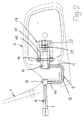
- the exterior rearview mirror can be attached in a known manner to the right and to the left outside of the motor vehicle. It has a mirror base 1, which has a transversely projecting support part 2, on which a mirror housing 3 is pivotally mounted about an upright axis in a manner to be described.
- a carrier plate 4 (FIG. 4) is adjustable in a known manner stored on which a mirror glass 5 is attached. As shown in FIG. 4, the carrier plate 4 is supported in the mirror housing 3 with a ball joint and can be adjusted to the desired position from the interior of the vehicle using an adjusting device 6.
- An adjusting lever 7 protrudes into the interior of the motor vehicle through the mirror base 1 and is mounted in the mirror base 1 by means of a ball 8 in a known manner. Via the ball 8, the adjusting lever 7 is rigidly connected to a U-shaped bracket 9, the leg 10 adjoining the ball 8 lying inside the mirror base 1. The other leg 11 of the bracket 9 protrudes into the mirror housing 3. Both legs 10, 11 are connected to one another by a web 12 which is arranged within the support part 2 of the mirror base 1. On the free end of the leg 11, an intermediate lever 13 is pivotally mounted, which has an axis 14 approximately in half length, which in the position of use of the exterior rearview mirror projects upwards and downwards over the intermediate lever 13.
- This axis 14 which is upright in the position of use of the exterior rear view mirror, protrude into elongated holes 15 and 16 which are provided in legs 17 and 18 of a U-shaped support 19.
- the intermediate lever 13 projects between the two mutually parallel legs 17, 18 of the carrier 19, which is firmly connected to the mirror housing 3.
- the legs 17, 18 extend in the direction of the mirror base 3 and lie at a small acute angle to the rear 20 of the mirror housing 3 (FIG. 4).
- the elongated holes 15, 16 are provided near the free ends of the legs 17, 18 and extend in the longitudinal direction thereof.
- the width of the elongated holes 15, 16 corresponds to the diameter of the axis 14.
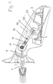
- the intermediate lever 13 is provided on its side facing away from the mirror base 1 with a peg-shaped extension 21 which has a ball 22 at the free end.
- the bearing part 23 is spaced from a bearing ball 24, which is provided centrally on the rear of the mirror glass support plate 4.
- the bearing ball 24 is received in a known manner in a bearing receptacle 25 (FIG. 4) which is provided in the mirror housing 3.
- the adjusting lever 7 and the bracket 9 of the adjusting device 6 lie in a common, upright plane.
- the bracket 9 is pivoted upwards. Since the intermediate lever 13 is axially fixed on the leg 11 of the bracket 9, the intermediate lever 13 is taken accordingly.
- the ball 22 is positively connected to the bearing part 23. Since the ball 22 is rigidly connected to the intermediate lever 13 via the extension 21, the mirror glass carrier plate 4 is pivoted accordingly in this way via the bearing part 23. Since the axis 14 projects through the elongated holes 15, 16, the axis can be moved within the elongated holes 15, 16 during the described adjustment movement, so that the described adjustment process is made possible.
- the intermediate lever 13 lies obliquely with respect to the legs 17, 18 of the carrier 19.
- control lever 7 can also be pivoted in the reverse direction by means of the bearing ball 8 in the position shown in dashed lines in a clockwise direction.
- the bracket 9, the intermediate lever 13 and the carrier plate 4 are adjusted accordingly.
- a cover part 26 is seated on the free end of the lever 7, so that the user of the adjusting device 6 can reliably actuate the adjusting lever 7.
- control lever 7 has been pivoted in the vertical direction. Due to the ball-and-socket mounting by means of the bearing ball 8, the adjusting lever 7 can of course be pivoted in any direction in order to adjust the carrier plate 4 to the required position.
- Fig. 5 shows the possibility of adjusting the lever 7, for example, in the horizontal direction. If the actuating lever 7 is pivoted clockwise from the position shown with solid lines into the position shown with dashed lines, the intermediate lever 13 is pivoted counterclockwise. In this case, the axis 14 of the intermediate lever 13 does not move in the elongated holes of the carrier 19, but rotates about its axis in the elongated holes. About the neck 21 and the ball 22 of the intermediate lever 13, the mirror glass support plate 4 is pivoted about its spherical bearing 24 also clockwise. In this case, the carrier plate 4 is adjusted about an imaginary vertical axis.
- the mirror housing 3 can fold down relative to the mirror base 1 in the event of a stroke in and against the direction of travel.
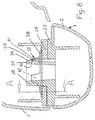
- a bearing part 27 is accommodated in the support part 2 of the mirror base 1, which has an upward-looking, sleeve-shaped extension 28 projecting upwards above the support part 2. It is provided at the free end with at least one undercut 29 on the outside (FIG. 8).
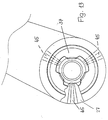
- three undercuts 29 are provided, which are preferably arranged uniformly distributed over the circumference of the extension 28.
- three radial projections 30 to 32 are provided at a distance from one another at the free end of the projection 28 (FIG. 12), each of which has a surface 33 to 35 lying on a conical surface.
- the spring washer 37 has a conical base body 38, the peripheral edge of which rests on a supporting part 39 of the mirror housing 3. He sits on the bearing part 27 of the mirror base 1.
- the base body 38 of the spring washer 37 tapers in the direction of the free end of the shoulder 28 of the bearing part 27. From the base body 38, three tabs 40 to 42 are preferably distributed obliquely upward over the circumference, with their free ends on the undersides 36 approaches 30 to 32 come into contact.
- the base body 38 and the tabs 40 to 42 of the spring washer 37 are designed such that the spring washer 37 is elastically prestressed in the assembled position. In this way, the mirror housing 3 with its supporting part 39 is pressed firmly against the bearing part 27 of the mirror base 1.
- the mirror housing 3 can pivot about the axis of the shoulder 28 of the bearing part 27 of the mirror base 1 in the corresponding direction.
- the spring washer 37 remains in its position, the support part 39 of the mirror housing 3 rotating relative to the spring washer 37 when pivoted. In the respectively pivoted position, the mirror housing 3 remains due to the prestress described by means of the spring washer 37.
- the mirror glass carrier plate 4 is not adjusted relative to the mirror housing 3. If the mirror housing 3 is pivoted back into the position of use, the mirror glass support plate 4 thereby assumes its original position of use.
- FIG. 9 to 11 show an embodiment of a spring washer 37, the base body 38 of which has locking elements 43 projecting opposite the tabs 40 to 42. They engage in corresponding locking recesses 44 in the support part 39 of the mirror housing 3.
- the locking elements 43 have, as shown in FIG. 11, part-circular cross-section. They are advantageously formed by features of the base body 38 of the spring washer 37. Otherwise, the spring washer 37 is of the same design as in the previous embodiment.
- the support part 39 since it is a component of the mirror housing 3, moves relative to the spring washer 37.
- the locking elements 43 therefore come out of the locking recesses 44. Since the locking elements 43 have part-circular cross-section, they simply come out of the locking recesses 44. If the mirror housing 3 is pivoted back into its starting position, the locking elements 43 automatically snap into the locking recesses 44.
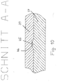
- the support part 39 of the mirror housing 3 in the use position of the mirror housing a defined position occupies the support member is advantageously provided with rib-like elevations 45 (Fig. 10 and 13), which have a trapezoidal cross-section and engage in corresponding recesses 46 in the support member 39 of the mirror housing 3.
- rib-like elevations 45 FIG. 10 and 13
- three such elevations 45 are advantageously provided over the circumference of the bearing part 27, each of which extends radially. Due to the trapezoidal cross-section, the support part 39 can easily get free from the elevations 45 of the bearing part 27 when the mirror housing 3 is folded down, which is stationary during this folding-down process.
Landscapes
- Engineering & Computer Science (AREA)
- Multimedia (AREA)
- Mechanical Engineering (AREA)
- Rear-View Mirror Devices That Are Mounted On The Exterior Of The Vehicle (AREA)
Abstract
Der Außenrückblickspiegel ist vorzugsweise für Kraftfahrzeuge vorgesehen. Er weist einen Spiegelfuß (1) und ein Spiegelgehäuse (3) auf, das gegenüber dem Spiegelfuß (1) abklappbar ist. Das Spiegelgehäuse (3) weist eine Spiegelglasträgerplatte auf, die mit einer Verstelleinrichtung (6) einstellbar ist. Sie hat ein vom Fahrzeuginnenraum aus betätigbares Stellelement (7). Damit bei einfacher konstruktiver Ausbildung der Verstelleinrichtung (6) die Spiegelglasträgerplatte nach dem Abklappen des Spiegelgehäuses (3) und dessen Zurückführen in die Gebrauchslage wieder ihre ursprünglich eingestellte Lage einnimmt, weist die Verstelleinrichtung (6) ein spiegelfußseitiges Stellteil (7, 9) auf, das mit einem spiegelgehäuseseitigen Stellteil (13, 19) über eine Achse (11) gelenkig verbunden ist. Sie liegt annähernd in der Klappachse des Spiegelgehäuses (3). Dadurch ist sichergestellt, daß die Spiegelglasträgerplatte ihre eingestellte Lage bezüglich des Spiegelgehäuses (3) beim Abklappen und Zurückklappen in die Gebrauchslage beibehält.
Description
Die Erfindung betrifft einen Außenrückblickspiegel für Fahrzeuge, vorzugsweise für Kraftfahrzeuge, nach dem Oberbegriff des Anspruches 1.The invention relates to an exterior rearview mirror for vehicles, preferably for motor vehicles, according to the preamble of
Es sind Außenrückblickspiegel bekannt, bei denen beim Abklappen des Spiegelgehäuses infolge eines Schlages die Verstelleinrichtung für die Spiegelglasträgerplatte ausrastet, um die Abklappbewegung des Spiegelgehäuses zu ermöglichen. Beim Zurückklappen des Spiegelgehäuses in die Gebrauchslage besteht dann das Problem, daß die Spiegelglasträgerplatte und die Verstelleinrichtung so miteinander verbunden werden, daß die Spiegelglasträgerplatte wieder ihre ursprüngliche Lage einnimmt.External rear-view mirrors are known in which the adjustment device for the mirror glass support plate disengages when the mirror housing is folded down as a result of a shock, in order to enable the mirror housing to fold down. When the mirror housing is folded back into the position of use, there is then the problem that the mirror glass carrier plate and the adjusting device are connected to one another in such a way that the mirror glass carrier plate returns to its original position.
Der Erfindung liegt die Aufgabe zugrunde, den gattungsgemäßen Außenrückblickspiegel so auszubilden, daß bei einfacher konstruktiver Ausbildung der Verstelleinrichtung gewährleistet ist, daß die Spiegelglasträgerplatte nach dem Abklappen des Spiegelgehäuses und dessen Zurückführen in die Gebrauchslage wieder ihre ursprünglich eingestellte Lage einnimmt.The invention has for its object to design the generic external rearview mirror so that with a simple construction of the adjustment device ensures that the mirror glass support plate after the mirror housing has been folded down and returned to the position of use resumes its originally set position.
Diese Aufgabe wird beim gattungsgemäßen Außenrückblickspiegel erfindungsgemäß mit den kennzeichnenden Merkmalen des Anspruches 1 gelöst.This object is achieved according to the invention in the generic exterior rear view mirror with the characterizing features of
Beim erfindungsgemäßen Außenrückblickspiegel rastet die Verstelleinrichtung beim Abklappen des Spiegelgehäuses nicht aus der Spiegelglasträgerplatte aus, sondern bleibt mit ihr verbunden. Die beiden Stellteile der Verstelleinrichtung werden gegeneinander verschwenkt, wenn das Spiegelgehäuse gegenüber dem Spiegelfuß abklappt. Dadurch ist sichergestellt, daß die Spiegelglasträgerplatte ihre eingestellte Lage bezüglich des Spiegelgehäuses beim Abklappen und Zurückklappen in die Gebrauchslage beibehält.In the exterior rear view mirror according to the invention, the adjustment device does not snap out of the mirror glass carrier plate when the mirror housing is folded down, but remains connected to it. The two control parts of the adjustment device are pivoted against each other when the mirror housing folds down relative to the mirror base. This ensures that the mirror glass support plate maintains its set position with respect to the mirror housing when folded down and folded back into the position of use.
Weitere Merkmale der Erfindung ergeben sich aus den weiteren Ansprüchen, der Beschreibung und den Zeichnungen.Further features of the invention result from the further claims, the description and the drawings.
Die Erfindung wird anhand zweier in den Zeichnungen dargestellter Ausführungsbeispiele näher erläutert. Es zeigen
- Fig. 1
- in Ansicht einen erfindungsgemäßen Außenrückblickspiegel,
- Fig. 2
- in schematischer Darstellung eine Verstelleinrichtung für den Spiegelglasträger des erfindungsgemäßen Außenrückblickspiegels in Ansicht,
- Fig. 3
- die Verstelleinrichtung gemäß Fig. 2, teilweise in Ansicht und teilweise im Schnitt,
- Fig. 4
- eine Draufsicht auf die Verstelleinrichtung des erfindungsgemäßen Außenrückblickspiegels,
- Fig. 5
- in einer Darstellung entsprechend Fig. 4 verschiedene Stellungen eines Spiegelglasträgers des erfindungsgemäßen Außenrückblickspiegels,
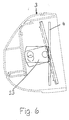
- Fig. 6
- in schematischer Darstellung eine Seitenansicht des Spiegelglasträgers, der zwei unterschiedliche Stellungen einnimmt,
- Fig. 7
- in einem Schnitt die Verbindung zwischen einem Spiegelfuß und einem Spiegelgehäuse des erfindungsgemäßen Außenrückblickspiegels,
- Fig. 8
- in vergrößerter Darstellung die Verbindungsstelle gemäß Fig. 7,
- Fig. 9
- in einer Darstellung entsprechend Fig. 7 eine zweite Ausführungsform eines erfindungsgemäßen Außenrückblickspiegels,
- Fig. 10
- in vergrößerter Darstellung einen Schnitt längs der Linie A-A in Fig. 7,
- Fig. 11
- in explosiver Darstellung die Verbindungsteile gemäß Fig. 9,
- Fig. 12
- eine Draufsicht auf den Verbindungsbereich gemäß Fig. 9,
- Fig. 13
- den Verbindungsbereich gemäß Fig. 12, teilweise im Schnitt.
- Fig. 1
- in view an exterior rear view mirror according to the invention,
- Fig. 2
- a schematic representation of an adjustment device for the mirror glass support of the exterior rearview mirror according to the invention in view,
- Fig. 3
- 2, partly in view and partly in section,
- Fig. 4
- a plan view of the adjusting device of the exterior rearview mirror according to the invention,
- Fig. 5
- 4 different positions of a mirror glass support of the exterior rear view mirror according to the invention,
- Fig. 6
- a schematic representation of a side view of the mirror glass carrier, which occupies two different positions,
- Fig. 7
- in a section the connection between a mirror base and a mirror housing of the exterior rearview mirror according to the invention,
- Fig. 8
- 7, the connection point according to FIG.
- Fig. 9
- 7 shows a second embodiment of an exterior rearview mirror according to the invention,
- Fig. 10
- an enlarged view a section along the line AA in Fig. 7,
- Fig. 11
- in an explosive representation the connecting parts according to FIG. 9,
- Fig. 12
- 9 shows a plan view of the connection area according to FIG. 9,
- Fig. 13
- 12, partly in section.
Der Außenrückblickspiegel kann in bekannter Weise an der rechten und an der linken Kraftfahrzeugaußenseite befestigt werden. Er hat einen Spiegelfuß 1, der einen quer abstehenden Tragteil 2 hat, auf dem in noch zu beschreibender Weise ein Spiegelgehäuse 3 um eine aufrechte Achse schwenkbar gelagert ist. Im Spiegelgehäuse 3 ist eine Trägerplatte 4 (Fig. 4) in bekannter Weise verstellbar gelagert, auf der ein Spiegelglas 5 befestigt ist. Wie Fig. 4 zeigt, ist die Trägerplatte 4 kugelgelenkig im Spiegelgehäuse 3 gelagert und kann mit einer Verstelleinrichtung 6 vom Fahrzeuginneren aus in die gewünschte Lage verstellt werden.The exterior rearview mirror can be attached in a known manner to the right and to the left outside of the motor vehicle. It has a
Durch den Spiegelfuß 1 ragte in das Kraftfahrzeuginnere ein Stellhebel 7, der innerhalb des Spiegelfußes 1 mittels einer Kugel 8 in bekannter Weise gelagert ist. Über die Kugel 8 ist der Stellhebel 7 starr mit einem U-förmigen Bügel 9 verbunden, dessen an die Kugel 8 anschließender Schenkel 10 innerhalb des Spiegelfußes 1 liegt. Der andere Schenkel 11 des Bügels 9 ragt in das Spiegelgehäuse 3. Beide Schenkel 10, 11 sind durch einen Steg 12 miteinander verbunden, der innerhalb des Tragteiles 2 des Spiegelfußes 1 angeordnet ist. Auf dem freien Ende des Schenkels 11 ist ein Zwischenhebel 13 schwenkbar gelagert, der etwa in halber Länge eine Achse 14 aufweist, die in der Gebrauchslage des Außenrückblickspiegels nach oben und unten über den Zwischenhebel 13 ragt. Die überstehenden Enden dieser in der Gebrauchslage des Außenrückblickspiegels aufrecht stehenden Achse 14 ragen in Langlöcher 15 und 16, die in Schenkein 17 und 18 eines U-förmigen Trägers 19 vorgesehen sind. Der Zwischenhebel 13 ragt zwischen die beiden zueinander parallelen Schenkel 17, 18 des Trägers 19, der fest mit dem Spiegelgehäuse 3 verbunden ist. Die Schenkel 17, 18 erstrecken sich in Richtung auf den Spiegelfuß 3 und liegen unter einem kleinen spitzen Winkel zur Rückseite 20 des Spiegelgehäuses 3 (Fig. 4). Die Langlöcher 15, 16 sind nahe den freien Enden der Schenkel 17, 18 vorgesehen und erstrecken sich in deren Längsrichtung. Die Breite der Langlöcher 15, 16 entspricht dem Durchmesser der Achse 14.An adjusting
Der Zwischenhebel 13 ist auf seiner vom Spiegelfuß 1 abgewandten Seite mit einem zapfenförmigen Ansatz 21 versehen, der am freien Ende eine Kugel 22 aufweist. Von der Rückseite der Spiegelglasträgerplatte 4 steht, wie Fig. 4 zeigt, ein Lagerteil 23 ab, in dem die Kugel 22 gelenkig gelagert ist. Das Lagerteil 23 liegt mit Abstand zu einer Lagerkugel 24, die zentrisch an der Rückseite der Spiegelglasträgerplatte 4 vorgesehen ist. Die Lagerkugel 24 ist in bekannter Weise in einer Lageraufnahme 25 aufgenommen (Fig. 4), die im Spiegelgehäuse 3 vorgesehen ist.The
Wie sich aus Fig. 4 ergibt, liegen der Stellhebel 7 und der Bügel 9 der Verstelleinrichtung 6 in einer gemeinsamen, aufrechten Ebene.4, the adjusting
Wird der Stellhebel 7 aus der in Fig. 1 mit ausgezogenen Linien dargestellte Lage in die mit gestrichelten Linien dargestellte Lage geschwenkt, wird der Bügel 9 aufwärts geschwenkt. Da der Zwischenhebel 13 axial fest auf dem Schenkel 11 des Bügels 9 sitzt, wird der Zwischenhebel 13 entsprechend mitgenommen. Die Kugel 22 ist formschlüssig mit dem Lagerteil 23 verbunden. Da die Kugel 22 über den Ansatz 21 starr mit dem Zwischenhebel 13 verbunden ist, wird auf diese Weise über den Lagerteil 23 die Spiegelglasträgerplatte 4 entsprechend geschwenkt. Da die Achse 14 durch die Langlöcher 15, 16 ragt, kann die Achse bei der beschriebenen Verstellbewegung innerhalb der Langlöcher 15, 16 bewegt werden, so daß der beschriebene Verstellvorgang ermöglicht wird. In den beiden in Fig. 1 dargestellten Stellungen liegt der Zwischenhebel 13 jeweils schräg in bezug auf die Schenkel 17, 18 des Trägers 19.If the adjusting
Aus Fig. 2 ergibt sich, daß der Stellhebel 7 auch in umgekehrter Richtung mittels der Lagerkugel 8 in die mit gestrichelten Linien dargestellte Lage im Uhrzeigersinn geschwenkt werden kann. Entsprechend werden der Bügel 9, der Zwischenhebel 13 und die Trägerplatte 4 verstellt.From Fig. 2 it follows that the
Wie sich aus Fig. 3 ergibt, sitzt auf dem freien Ende des Hebels 7 ein Abdeckteil 26, so daß der Benutzer der Verstelleinrichtung 6 den Stellhebel 7 zuverlässig betätigen kann.As can be seen from FIG. 3, a
Bei der beschriebenen Verstellung ist der Stellhebel 7 jeweils in vertikaler Richtung geschwenkt worden. Aufgrund der kugelgelenkigen Lagerung mittels der Lagerkugel 8 kann der Stellhebel 7 selbstverständlich in jeder Richtung geschwenkt werden, um die Trägerplatte 4 in die erforderliche Lage zu verstellen.In the described adjustment, the
Fig. 5 zeigt die Möglichkeit, den Stellhebel 7 beispielsweise auch in horizontaler Richtung zu verstellen. Wird der Stellhebel 7 aus der mit ausgezogenen Linien dargestellten Lage im Uhrzeigersinn in die mit gestrichelten Linien dargestellte Lage verschwenkt, wird der Zwischenhebel 13 entgegen dem Uhrzeigersinn verschwenkt. In diesem Falle verschiebt sich die Achse 14 des Zwischenhebels 13 nicht in den Langlöchern des Trägers 19, sondern dreht in den Langlöchern um ihre Achse. Über den Ansatz 21 und die Kugel 22 des Zwischenhebels 13 wird die Spiegelglasträgerplatte 4 um ihre kugelgelenkige Lagerung 24 ebenfalls im Uhrzeigersinn verschwenkt. In diesem Falle wird die Trägerplatte 4 um eine gedachte vertikale Achse verstellt.Fig. 5 shows the possibility of adjusting the
Wird der Stellhebel 7, wie anhand der Fig. 1 und 2 beschrieben worden ist, in vertikaler Richtung bewegt, dann wird auch der Lagerteil 23 an der Rückseite der Trägerplatte 4 in vertikaler Richtung verschwenkt. Dies hat zur Folge, daß die Spiegelglasträgerplatte 4 um eine gedachte horizontale Achse in ihrer Neigung eingestellt wird. In Fig. 6 sind mit ausgezogenen und gestrichelten Linien zwei mögliche Einstellagen der Trägerplatte 4 dargestellt, wenn der Stellhebel 7 in Vertikalrichtung verschwenkt wird.If the adjusting
Das Spiegelgehäuse 3 kann gegenüber dem Spiegelfuß 1 bei einem Schlag in und entgegen Fahrtrichtung abklappen. Wie die Fig. 7 und 8 zeigen, ist im Tragteil 2 des Spiegelfußes 1 ein Lagerteil 27 untergebracht, das einen aufwärts gerichteten, nach oben über den Tragteil 2 vorstehenden hülsenförmigen Ansatz 28 aufweist. Er ist am freien Ende mit mindestens einer außenseitigen Hinterschneidung 29 versehen (Fig. 8). Im dargestellten Ausführungsbeispiel sind drei Hinterschneidungen 29 vorgesehen, die über den Umfang des Ansatzes 28 vorzugsweise gleichmäßig verteilt angeordnet sind. Zur Bildung der Hinterschneidungen 29 sind am freien Ende des Ansatzes 28 drei mit Abstand voneinander vorgesehene radiale Ansätze 30 bis 32 vorgesehen (Fig. 12), die jeweils eine auf einem Kegelmantel liegende Fläche 33 bis 35 haben. Sie gehen jeweils spitzwinklig in eine radial zur Achse des Ansatzes 28 liegende Unterseite über, von denen in Fig. 8 die Unterseite 36 des Ansatzes 31 dargestellt ist. Diese Unterseiten 36 bilden die Hinterschneidungen 29. Sie dienen als Widerlager für eine Federscheibe 37, mit welcher das Spiegelgehäuse 3 in noch zu beschreibender Weise reibschlüssig mit dem Spiegelfuß 1 verbunden wird.The
Die Federscheibe 37 hat einen konischen Grundkörper 38, dessen umlaufender Rand auf einem Tragteil 39 des Spiegelgehäuses 3 aufliegt. Er sitzt auf dem Lagerteil 27 des Spiegelfußes 1 auf.The
Der Grundkörper 38 der Federscheibe 37 verjüngt sich in Richtung auf das freie Ende des Ansatzes 28 des Lager teiles 27. Vom Grundkörper 38 stehen über den Umfang vorzugsweise gleichmäßig verteilt drei Lappen 40 bis 42 schräg nach oben, die mit ihren freien Enden an den Unterseiten 36 der Ansätze 30 bis 32 zur Anlage kommen. Der Grundkörper 38 und die Lappen 40 bis 42 der Federscheibe 37 sind so ausgebildet, daß in der montierten Lage die Federscheibe 37 elastisch vorgespannt ist. Auf diese Weise wird das Spiegelgehäuse 3 mit seinem Tragteil 39 fest gegen den Lagerteil 27 des Spiegelfußes 1 gedrückt.The
Wird auf das Spiegelgehäuse 3 ein Schlag in oder entgegen Fahrtrichtung des Kraftfahrzeuges ausgeübt, kann das Spiegelgehäuse 3 um die Achse des Ansatzes 28 des Lagerteiles 27 des Spiegelfußes 1 in der entsprechenden Richtung schwenken. Die Federscheibe 37 bleibt hierbei in ihrer Lage, wobei sich beim Verschwenken der Tragteil 39 des Spiegelgehäuses 3 relativ zur Federscheibe 37 dreht. In der jeweils verschwenkten Lage bleibt das Spiegelgehäuse 3 infolge der beschriebenen Vorspannung mittels der Federscheibe 37 stehen. Bei diesem Schwenkvorgang wird die Spiegelglasträgerplatte 4 nicht relativ zum Spiegelgehäuse 3 verstellt. Wird das Spiegelgehäuse 3 wieder in die Gebrauchslage zurückgeschwenkt, nimmt dadurch die Spiegelglasträgerplatte 4 ihre ursprüngliche Gebrauchslage ein. Dies ist darauf zurückzuführen, daß die Schwenk- bzw. Klappachse des Spiegelgehäuses 3 zumindest annähernd in der Achse des Schenkels 11 des Bügels 9 liegt. Dadurch bleibt beim Abklappen des Spiegelgehäuses 3 der Stellhebel 7 mit dem Bügel 9 in seiner eingestellten Lage stehen, während der Zwischenhebel 13 beim Abklappvorgang relativ zum Bügel 9 verstellt wird. Dadurch bleibt die Spiegelglasträgerplatte 4 in ihrer jeweils eingestellten Lage relativ zum Spiegelgehäuse 3 stehen.If an impact is exerted on the
In den Fig. 9 bis 11 ist eine Ausführungsform einer Federscheibe 37 dargestellt, deren Grundkörper 38 entgegengesetzt zu den Lappen 40 bis 42 vorstehende Rastelemente 43 aufweist. Sie greifen in entsprechende Rastvertiefungen 44 des Tragteiles 39 des Spiegelgehäuses 3 ein. Die Rastelemente 43 haben, wie Fig. 11 zeigt, teilkreisförmigen Querschnitt. Vorteilhaft sind sie durch Ausprägungen des Grundkörpers 38 der Federscheibe 37 gebildet. Im übrigen ist die Federscheibe 37 gleich ausgebildet wie beim vorigen Ausführungsbeispiel.9 to 11 show an embodiment of a
Wird das Spiegelgehäuse 3 in Fahrtrichtung nach vorn oder nach hinten gegenüber dem Spiegelfuß 1 abgeklappt, bewegt sich der Tragteil 39, da er Bestandteil des Spiegelgehäuses 3 ist, relativ zur Federscheibe 37. Die Rastelemente 43 gelangen darum aus den Rastvertiefungen 44. Da die Rastelemente 43 teilkreisförmigen Querschnitt haben, gelangen sie einfach aus den Rastvertiefungen 44. Wird das Spiegelgehäuse 3 wieder in seine Ausgangslage zurückgeschwenkt, rasten die Rastelemente 43 selbsttätig in die Rastvertiefungen 44 ein.If the
Damit auch bei der Ausführungsform gemäß den Fig. 7, 8 und 12 der Tragteil 39 des Spiegelgehäuses 3 in der Gebrauchslage des Spiegelgehäuses eine definierte Lage einnimmt, ist der Tragteil vorteilhaft mit rippenartigen Erhöhungen 45 versehen (Fig. 10 und 13), die trapezförmigen Querschnitt haben und in entsprechende Vertiefungen 46 im Tragteil 39 des Spiegelgehäuses 3 eingreifen. Wie Fig. 13 zeigt, sind über den Umfang des Lagerteiles 27 vorteilhaft drei derartige Erhöhungen 45 vorgesehen, die jeweils radial verlaufen. Aufgrund des trapezförmigen Querschnittes kann das Tragteil 39 beim Abklappen des Spiegelgehäuses 3 leicht von den Erhöhungen 45 des Lagerteiles 27 freikommen, der bei diesem Abklappvorgang still steht.Thus, also in the embodiment according to FIGS. 7, 8 and 12, the
Aufgrund der beschriebenen Ausbildung der Federscheibe 37 sind zusätzliche Druckfedern nicht erforderlich. Die Lappen 40 bis 42 der Federscheibe 37 stützen sich an den Ansätzen 30 bis 32 des Ansatzes 28 des Lagerteiles 27 so ab, daß die Federscheibe 37 elastisch vorgespannt ist und auf diese Weise den Tragteil 39 des Spiegelgehäuses 3 fest gegen den Lagerteil 27 des Spiegelfußes 1 drückt.Due to the design of the
Claims (11)
dadurch gekennzeichnet, daß die Verstelleinrichtung (6) ein spiegelfußseitiges Stellteil (7, 9) aufweist, das mit einem spiegelgehäuseseitigen Stellteil (13, 19) über eine Achse (11) gelenkig verbunden ist, die zumindest annähernd in der Klappachse des Spiegelgehäuses (3) liegt.Exterior rear-view mirror for vehicles, preferably for motor vehicles, with a mirror base and a mirror housing that can be folded down relative to the mirror base and has a mirror glass support plate that can be adjusted with an adjustment device that has an actuating element that can be actuated from the vehicle interior,
characterized in that the adjusting device (6) has an adjusting part (7, 9) on the mirror foot side which is articulated to an adjusting part (13, 19) on the mirror housing side via an axis (11) which is at least approximately in the folding axis of the mirror housing (3) lies.
dadurch gekennzeichnet, daß das spiegelfußseitige Stellteil (7, 9) im Spiegelfuß (1) gelenkig gelagert ist und vorzugsweise das als einarmiger Hebel ausgebildete Stellelement (7) aufweist, das mit einem Zwischenelement (9) starr verbunden ist.Exterior rear view mirror according to claim 1,
characterized in that the mirror base-side adjusting part (7, 9) is articulated in the mirror base (1) and preferably has the adjusting element (7) designed as a one-armed lever, which is rigidly connected to an intermediate element (9).
dadurch gekennzeichnet, daß das Zwischenelement (9) ein U-förmiger Bügel ist, dessen einer Schenkel (11) die Gelenkachse bildet, und daß vorzugsweise der andere Schenkel (10) des Zwischenelementes (9) mit einer Lagerkugel (8) fest verbunden ist, an der auch das Stellelement (7) befestigt ist, das vorteilhaft mit dem Zwischenelement (9) in einer gemeinsamen Ebene liegt.Exterior rear view mirror according to claim 2,
characterized in that the intermediate element (9) is a U-shaped bracket, one leg (11) of which forms the hinge axis, and that preferably the other leg (10) of the intermediate element (9) is firmly connected to a bearing ball (8), to which the adjusting element (7) is also fastened, which advantageously lies in a common plane with the intermediate element (9).
dadurch gekennzeichnet, daß das spiegelgehäuseseitige Stellteil (13, 19) ein Stellelement (13) aufweist, das drehbar auf der Gelenkachse (11) des spiegelfußseitigen Stellteiles (7, 9) gelagert ist.Exterior rear view mirror according to one of claims 1 to 3,
characterized in that the control element (13, 19) on the mirror housing side has an control element (13) which is rotatably mounted on the hinge axis (11) of the control element (7, 9) on the mirror foot side.
dadurch gekennzeichnet, daß das spiegelgehäuseseitige Stellelement (13) mit einer Achse (14) in einem Träger (19) gelagert ist, der fest mit dem Spiegelgehäuse (3) verbunden ist, und daß vorzugsweise die Achse (14) des Stellelementes (13) quer zu ihrer Achsrichtung begrenzt beweglich im Träger (19) gelagert ist.Exterior rear view mirror according to claim 4,
characterized in that the mirror housing-side adjusting element (13) is mounted with an axis (14) in a carrier (19) which is fixedly connected to the mirror housing (3), and that preferably the axis (14) of the adjusting element (13) is transverse limited to its axial direction is mounted in the carrier (19).
dadurch gekennzeichnet, daß der Träger (19) zwei zueinander parallele Schenkel (17, 18) aufweist, die mit jeweils einem Langloch (15, 16) versehen sind, in welche die Achse (14) des spiegelgehäuseseitigen Stellelementes (13) eingreift, das vorzugsweise gelenkig mit der Spiegelglasträgerplatte (4) verbunden ist.Exterior rearview mirror according to claim 5,
characterized in that the carrier (19) has two mutually parallel legs (17, 18) which are each provided with an elongated hole (15, 16) into which the axis (14) of the adjusting element (13) on the mirror housing side engages, which preferably is articulated to the mirror glass support plate (4).
dadurch gekennzeichnet, daß von der Rückseite der Spiegelglasträgerplatte (4) ein Lagerteil (23) absteht, in welches das spiegelgehäuseseitige Stellelement (13) eingreift.Exterior rear view mirror according to one of claims 4 to 6,
characterized in that a bearing part (23) protrudes from the rear of the mirror glass support plate (4), into which the adjusting element (13) on the mirror housing side engages.
dadurch gekennzeichnet, daß das Spiegelgehäuse (3) gegen den Spiegelfuß (1) durch wenigstens eine Federscheibe (37) gedrückt ist, die sich unter elastischer Vorspannung spiegelgehäuseseitig und am Spiegelfuß (1) abstützt.Exterior rearview mirror for vehicles, preferably for motor vehicles, with a mirror base and a mirror housing that can be folded down relative to the mirror base, in particular according to one of claims 1 to 7,
characterized in that the mirror housing (3) is pressed against the mirror base (1) by at least one spring washer (37) which is supported on the mirror housing side and on the mirror base (1) under elastic pretension.
dadurch gekennzeichnet, daß die Federscheibe (37) einen Ansatz (28) des Spiegelfußes (1) umgibt, und daß vorzugsweise das Spiegelgehäuse (3) mit einem Tragteil (39) den Ansatz (28) umgibt, an dem vorteilhaft die Federscheibe (37) abgestützt ist.Exterior rearview mirror according to claim 8,
characterized in that the spring washer (37) surrounds a shoulder (28) of the mirror base (1), and that preferably the mirror housing (3) with a supporting part (39) surrounds the shoulder (28) on which the spring washer (37) advantageously is supported.
dadurch gekennzeichnet, daß der Ansatz (28) mindestens ein Widerlager (30 bis 32) für die Federscheibe (37) aufweist, die vorzugsweise mindestens einen lappenförmigen Ansatz (40 bis 42) aufweist, der sich am Widerlager (30 bis 32) des Ansatzes (28) abstützt.Exterior rearview mirror according to claim 9,
characterized in that the extension (28) has at least one abutment (30 to 32) for the spring washer (37), which preferably has at least one tab-shaped extension (40 to 42) which is located on the abutment (30 to 32) of the extension ( 28) supports.
dadurch gekennzeichnet, daß die Federscheibe (37) mindestens ein Rastelement (43, 46) aufweist, das mit mindestens einem spiegelfußseitigen Rastgegenelement (44, 45) zusammenwirkt.Exterior rear view mirror according to one of claims 8 to 10,
characterized in that the spring washer (37) has at least one locking element (43, 46) which interacts with at least one locking counter element (44, 45) on the mirror base side.
Applications Claiming Priority (2)
| Application Number | Priority Date | Filing Date | Title |
|---|---|---|---|
| DE19615476 | 1996-04-19 | ||
| DE19615476A DE19615476A1 (en) | 1996-04-19 | 1996-04-19 | Exterior rear view mirror |
Publications (2)
| Publication Number | Publication Date |
|---|---|
| EP0802083A2 true EP0802083A2 (en) | 1997-10-22 |
| EP0802083A3 EP0802083A3 (en) | 2001-02-07 |
Family
ID=7791735
Family Applications (1)
| Application Number | Title | Priority Date | Filing Date |
|---|---|---|---|
| EP97104127A Withdrawn EP0802083A3 (en) | 1996-04-19 | 1997-03-12 | Exterior rearview mirror |
Country Status (3)
| Country | Link |
|---|---|
| US (1) | US5909326A (en) |
| EP (1) | EP0802083A3 (en) |
| DE (1) | DE19615476A1 (en) |
Cited By (1)
| Publication number | Priority date | Publication date | Assignee | Title |
|---|---|---|---|---|
| WO2014206640A3 (en) * | 2013-03-15 | 2015-05-28 | Magna Mirrors Holding Gmbh | Rear-view mirror assembly for motor vehicles |
Families Citing this family (7)
| Publication number | Priority date | Publication date | Assignee | Title |
|---|---|---|---|---|
| US6206529B1 (en) * | 1999-06-09 | 2001-03-27 | Kabushiki Kaisha Tokai-Rika-Denki-Seisakusho | Vehicle mirror device |
| DE29917714U1 (en) * | 1999-10-07 | 1999-12-16 | Reitter & Schefenacker GmbH & Co. KG, 73730 Esslingen | Exterior rear view mirror for vehicles, in particular motor vehicles |
| US7303297B1 (en) * | 2003-02-27 | 2007-12-04 | Magna Donnelly Mirrors North America L.L.C. | Vehicular mirror with improved bearing fit |
| DE602004030627D1 (en) * | 2004-10-01 | 2011-01-27 | Murakami Corp | FASTENABLE DOOR MIRROR |
| WO2013166265A2 (en) * | 2012-05-02 | 2013-11-07 | Rosco, Inc. | Mirror assembly and adjustment mechanism thereof |
| JP6618415B2 (en) * | 2016-04-08 | 2019-12-11 | 株式会社東海理化電機製作所 | Vehicle visual recognition device |
| DE102017200381A1 (en) * | 2017-01-11 | 2018-07-12 | Ford Global Technologies, Llc | mirror device |
Family Cites Families (10)
| Publication number | Priority date | Publication date | Assignee | Title |
|---|---|---|---|---|
| DE3268988D1 (en) * | 1981-10-22 | 1986-03-20 | Britax Wingard Ltd | Exterior rear view mirror |
| US4636045A (en) * | 1983-09-01 | 1987-01-13 | Kabushiki Kaisha Tokai Rika Denki Seisakusho | Manual adjusting device for tiltable outer mirror |
| DE3429713A1 (en) * | 1984-08-11 | 1986-02-20 | Hohe Kg, 6981 Collenberg | EXTERIOR MIRROR FOR MOTOR VEHICLES |
| JPH0620858B2 (en) * | 1984-11-08 | 1994-03-23 | 株式会社東海理化電機製作所 | Manual adjustment device for retractable mirrors |
| DE3638876A1 (en) * | 1986-11-10 | 1988-05-19 | Hohe Kg | Foldable wing mirror for a vehicle with a mechanically adjustable mirror |
| DE8701766U1 (en) * | 1987-02-06 | 1987-07-16 | Hohe Kg, 6981 Collenberg | Exterior mirror for a vehicle with mechanically adjustable mirror |
| US5182676A (en) * | 1988-08-04 | 1993-01-26 | Honda Giken Kogyo Kabushiki Kaisha | Turn-over type rearview door mirror |
| JPH0361451U (en) * | 1989-10-19 | 1991-06-17 | ||
| US4981279A (en) * | 1989-11-07 | 1991-01-01 | Sheller-Globe Corporation | Adjustable rear view mirror |
| ES2026048A6 (en) * | 1990-10-11 | 1992-04-01 | Fico Mirrors Sa | Spring fixing device for exterior retractable rearview mirrors of motor vehicles. |
-
1996
- 1996-04-19 DE DE19615476A patent/DE19615476A1/en not_active Withdrawn
-
1997
- 1997-03-12 EP EP97104127A patent/EP0802083A3/en not_active Withdrawn
- 1997-04-18 US US08/844,095 patent/US5909326A/en not_active Expired - Fee Related
Cited By (1)
| Publication number | Priority date | Publication date | Assignee | Title |
|---|---|---|---|---|
| WO2014206640A3 (en) * | 2013-03-15 | 2015-05-28 | Magna Mirrors Holding Gmbh | Rear-view mirror assembly for motor vehicles |
Also Published As
| Publication number | Publication date |
|---|---|
| DE19615476A1 (en) | 1997-10-23 |
| US5909326A (en) | 1999-06-01 |
| EP0802083A3 (en) | 2001-02-07 |
Similar Documents
| Publication | Publication Date | Title |
|---|---|---|
| DE69725246T2 (en) | steering wheel | |
| EP1040962B1 (en) | Interior rear view mirror for vehicles, especially motor vehicles | |
| DE10343492B4 (en) | An armrest assembly for a vehicle seat and method of assembling an armrest assembly for a vehicle seat | |
| DE10351157B3 (en) | Automotive seat | |
| EP2611673B1 (en) | Steering column for a motor vehicle | |
| DE60027656T2 (en) | Shock absorbing steering device | |
| DE3043945A1 (en) | HOLDING DEVICE FOR A HEADREST OF A VEHICLE SEAT | |
| EP1107878B1 (en) | Child seat fixing device | |
| DE19628861B4 (en) | Vehicle seat, in particular for a passenger car | |
| DE3510274C2 (en) | ||
| EP0697311A1 (en) | Support for a truck rearview mirror | |
| EP0802083A2 (en) | Exterior rearview mirror | |
| DE4427410B4 (en) | Exterior rearview mirror for motor vehicles | |
| EP0614782B1 (en) | External rear view mirror for vehicles, preferably for motor vehicles | |
| EP1423293B1 (en) | Fitting for a vehicle seat | |
| DE19739798A1 (en) | Seat with headrest for motor vehicles | |
| DE19854985A1 (en) | Armrest for location between seat backs of rear seat in motor vehicle has pivot bearing installed between table top and rotatable component and has two sections which are connected to pivot around axis perpendicular to vertical axis | |
| DE10145240B4 (en) | Headrest for vehicle seats | |
| EP1373015A1 (en) | Vehicle seat with bearing device | |
| EP0092665B1 (en) | Catching device for the arm of a lorry rearview mirror | |
| DE10342832B4 (en) | Automotive seat | |
| DE19957523C2 (en) | Adjustment mechanism for a swivel-adjustable adjustment part, in particular for an armrest of a motor vehicle | |
| DE19754831A1 (en) | Arrangement for gap covering on a recess | |
| DE2940141C2 (en) | Backrest adjustment device | |
| DE9005572U1 (en) | Car jack |
Legal Events
| Date | Code | Title | Description |
|---|---|---|---|
| PUAI | Public reference made under article 153(3) epc to a published international application that has entered the european phase |
Free format text: ORIGINAL CODE: 0009012 |
|
| AK | Designated contracting states |
Kind code of ref document: A2 Designated state(s): BE DE ES FR GB IT LU |
|
| K1C1 | Correction of patent application (title page) published |
Effective date: 19971022 |
|
| PUAL | Search report despatched |
Free format text: ORIGINAL CODE: 0009013 |
|
| AK | Designated contracting states |
Kind code of ref document: A3 Designated state(s): BE DE ES FR GB IT LU |
|
| 17P | Request for examination filed |
Effective date: 20010514 |
|
| 17Q | First examination report despatched |
Effective date: 20040423 |
|
| STAA | Information on the status of an ep patent application or granted ep patent |
Free format text: STATUS: THE APPLICATION IS DEEMED TO BE WITHDRAWN |
|
| 18D | Application deemed to be withdrawn |
Effective date: 20041104 |