EP0801760B1 - Verfahren zur ermittlung der distanz zwischen einem objektdetail und einem operationsmikroskop und vorrichtung dazu - Google Patents
Verfahren zur ermittlung der distanz zwischen einem objektdetail und einem operationsmikroskop und vorrichtung dazu Download PDFInfo
- Publication number
- EP0801760B1 EP0801760B1 EP95914352A EP95914352A EP0801760B1 EP 0801760 B1 EP0801760 B1 EP 0801760B1 EP 95914352 A EP95914352 A EP 95914352A EP 95914352 A EP95914352 A EP 95914352A EP 0801760 B1 EP0801760 B1 EP 0801760B1
- Authority
- EP
- European Patent Office
- Prior art keywords
- light
- microscope
- feature
- sensor
- bundle
- Prior art date
- Legal status (The legal status is an assumption and is not a legal conclusion. Google has not performed a legal analysis and makes no representation as to the accuracy of the status listed.)
- Expired - Lifetime
Links
- 238000000034 method Methods 0.000 title claims description 28
- 230000003287 optical effect Effects 0.000 claims description 41
- 238000005259 measurement Methods 0.000 claims description 35
- 230000010363 phase shift Effects 0.000 claims description 9
- 230000005540 biological transmission Effects 0.000 claims description 3
- 230000008859 change Effects 0.000 claims description 3
- 239000011521 glass Substances 0.000 claims description 3
- 230000010355 oscillation Effects 0.000 claims 2
- 238000005553 drilling Methods 0.000 claims 1
- 230000035945 sensitivity Effects 0.000 claims 1
- 230000001427 coherent effect Effects 0.000 description 6
- 230000006870 function Effects 0.000 description 4
- 230000008569 process Effects 0.000 description 4
- 238000012937 correction Methods 0.000 description 3
- 230000008901 benefit Effects 0.000 description 2
- 230000008878 coupling Effects 0.000 description 2
- 238000010168 coupling process Methods 0.000 description 2
- 238000005859 coupling reaction Methods 0.000 description 2
- 230000001419 dependent effect Effects 0.000 description 2
- 238000011156 evaluation Methods 0.000 description 2
- 239000000835 fiber Substances 0.000 description 2
- 238000003780 insertion Methods 0.000 description 2
- 230000037431 insertion Effects 0.000 description 2
- 230000005693 optoelectronics Effects 0.000 description 2
- 210000001747 pupil Anatomy 0.000 description 2
- 230000003595 spectral effect Effects 0.000 description 2
- 230000002123 temporal effect Effects 0.000 description 2
- 230000000007 visual effect Effects 0.000 description 2
- 229910000831 Steel Inorganic materials 0.000 description 1
- 230000001154 acute effect Effects 0.000 description 1
- 210000004556 brain Anatomy 0.000 description 1
- 239000011248 coating agent Substances 0.000 description 1
- 238000000576 coating method Methods 0.000 description 1
- 239000003086 colorant Substances 0.000 description 1
- 238000010276 construction Methods 0.000 description 1
- 230000006735 deficit Effects 0.000 description 1
- 238000001514 detection method Methods 0.000 description 1
- 210000000887 face Anatomy 0.000 description 1
- 238000005562 fading Methods 0.000 description 1
- 239000005357 flat glass Substances 0.000 description 1
- 238000003384 imaging method Methods 0.000 description 1
- 230000001771 impaired effect Effects 0.000 description 1
- 238000000691 measurement method Methods 0.000 description 1
- 238000002406 microsurgery Methods 0.000 description 1
- 239000013307 optical fiber Substances 0.000 description 1
- 230000000737 periodic effect Effects 0.000 description 1
- 230000010287 polarization Effects 0.000 description 1
- 238000012545 processing Methods 0.000 description 1
- 230000000644 propagated effect Effects 0.000 description 1
- 238000001454 recorded image Methods 0.000 description 1
- 239000004065 semiconductor Substances 0.000 description 1
- 230000009131 signaling function Effects 0.000 description 1
- 239000010959 steel Substances 0.000 description 1
- 238000012549 training Methods 0.000 description 1
- 238000011144 upstream manufacturing Methods 0.000 description 1
Images



Classifications
-
- G—PHYSICS
- G01—MEASURING; TESTING
- G01S—RADIO DIRECTION-FINDING; RADIO NAVIGATION; DETERMINING DISTANCE OR VELOCITY BY USE OF RADIO WAVES; LOCATING OR PRESENCE-DETECTING BY USE OF THE REFLECTION OR RERADIATION OF RADIO WAVES; ANALOGOUS ARRANGEMENTS USING OTHER WAVES
- G01S7/00—Details of systems according to groups G01S13/00, G01S15/00, G01S17/00
- G01S7/48—Details of systems according to groups G01S13/00, G01S15/00, G01S17/00 of systems according to group G01S17/00
- G01S7/481—Constructional features, e.g. arrangements of optical elements
- G01S7/4811—Constructional features, e.g. arrangements of optical elements common to transmitter and receiver
-
- G—PHYSICS
- G01—MEASURING; TESTING
- G01B—MEASURING LENGTH, THICKNESS OR SIMILAR LINEAR DIMENSIONS; MEASURING ANGLES; MEASURING AREAS; MEASURING IRREGULARITIES OF SURFACES OR CONTOURS
- G01B11/00—Measuring arrangements characterised by the use of optical techniques
- G01B11/02—Measuring arrangements characterised by the use of optical techniques for measuring length, width or thickness
- G01B11/026—Measuring arrangements characterised by the use of optical techniques for measuring length, width or thickness by measuring distance between sensor and object
-
- G—PHYSICS
- G01—MEASURING; TESTING
- G01B—MEASURING LENGTH, THICKNESS OR SIMILAR LINEAR DIMENSIONS; MEASURING ANGLES; MEASURING AREAS; MEASURING IRREGULARITIES OF SURFACES OR CONTOURS
- G01B9/00—Measuring instruments characterised by the use of optical techniques
- G01B9/04—Measuring microscopes
-
- G—PHYSICS
- G01—MEASURING; TESTING
- G01S—RADIO DIRECTION-FINDING; RADIO NAVIGATION; DETERMINING DISTANCE OR VELOCITY BY USE OF RADIO WAVES; LOCATING OR PRESENCE-DETECTING BY USE OF THE REFLECTION OR RERADIATION OF RADIO WAVES; ANALOGOUS ARRANGEMENTS USING OTHER WAVES
- G01S17/00—Systems using the reflection or reradiation of electromagnetic waves other than radio waves, e.g. lidar systems
- G01S17/02—Systems using the reflection of electromagnetic waves other than radio waves
- G01S17/06—Systems determining position data of a target
- G01S17/08—Systems determining position data of a target for measuring distance only
- G01S17/32—Systems determining position data of a target for measuring distance only using transmission of continuous waves, whether amplitude-, frequency-, or phase-modulated, or unmodulated
-
- G—PHYSICS
- G01—MEASURING; TESTING
- G01S—RADIO DIRECTION-FINDING; RADIO NAVIGATION; DETERMINING DISTANCE OR VELOCITY BY USE OF RADIO WAVES; LOCATING OR PRESENCE-DETECTING BY USE OF THE REFLECTION OR RERADIATION OF RADIO WAVES; ANALOGOUS ARRANGEMENTS USING OTHER WAVES
- G01S17/00—Systems using the reflection or reradiation of electromagnetic waves other than radio waves, e.g. lidar systems
- G01S17/02—Systems using the reflection of electromagnetic waves other than radio waves
- G01S17/06—Systems determining position data of a target
- G01S17/42—Simultaneous measurement of distance and other co-ordinates
-
- G—PHYSICS
- G01—MEASURING; TESTING
- G01S—RADIO DIRECTION-FINDING; RADIO NAVIGATION; DETERMINING DISTANCE OR VELOCITY BY USE OF RADIO WAVES; LOCATING OR PRESENCE-DETECTING BY USE OF THE REFLECTION OR RERADIATION OF RADIO WAVES; ANALOGOUS ARRANGEMENTS USING OTHER WAVES
- G01S17/00—Systems using the reflection or reradiation of electromagnetic waves other than radio waves, e.g. lidar systems
- G01S17/87—Combinations of systems using electromagnetic waves other than radio waves
- G01S17/875—Combinations of systems using electromagnetic waves other than radio waves for determining attitude
-
- G—PHYSICS
- G01—MEASURING; TESTING
- G01S—RADIO DIRECTION-FINDING; RADIO NAVIGATION; DETERMINING DISTANCE OR VELOCITY BY USE OF RADIO WAVES; LOCATING OR PRESENCE-DETECTING BY USE OF THE REFLECTION OR RERADIATION OF RADIO WAVES; ANALOGOUS ARRANGEMENTS USING OTHER WAVES
- G01S17/00—Systems using the reflection or reradiation of electromagnetic waves other than radio waves, e.g. lidar systems
- G01S17/88—Lidar systems specially adapted for specific applications
-
- G—PHYSICS
- G01—MEASURING; TESTING
- G01S—RADIO DIRECTION-FINDING; RADIO NAVIGATION; DETERMINING DISTANCE OR VELOCITY BY USE OF RADIO WAVES; LOCATING OR PRESENCE-DETECTING BY USE OF THE REFLECTION OR RERADIATION OF RADIO WAVES; ANALOGOUS ARRANGEMENTS USING OTHER WAVES
- G01S5/00—Position-fixing by co-ordinating two or more direction or position line determinations; Position-fixing by co-ordinating two or more distance determinations
- G01S5/16—Position-fixing by co-ordinating two or more direction or position line determinations; Position-fixing by co-ordinating two or more distance determinations using electromagnetic waves other than radio waves
- G01S5/163—Determination of attitude
-
- G—PHYSICS
- G02—OPTICS
- G02B—OPTICAL ELEMENTS, SYSTEMS OR APPARATUS
- G02B21/00—Microscopes
- G02B21/0004—Microscopes specially adapted for specific applications
- G02B21/0012—Surgical microscopes
-
- A—HUMAN NECESSITIES
- A61—MEDICAL OR VETERINARY SCIENCE; HYGIENE
- A61B—DIAGNOSIS; SURGERY; IDENTIFICATION
- A61B90/00—Instruments, implements or accessories specially adapted for surgery or diagnosis and not covered by any of the groups A61B1/00 - A61B50/00, e.g. for luxation treatment or for protecting wound edges
- A61B90/20—Surgical microscopes characterised by non-optical aspects
Definitions
- the invention relates to a method according to claim 1 and a device according to Claim 10.
- WO 90/11487 describes an optical device for determining the surface profile known on a wafer where the height differences are adjacent Object points can be determined.
- the application of the present invention is primarily medical Field using surgical microscopes.
- the field of view must always be placed on an object detail to be processed can. Because the focus is often not due to the object structures shown can be achieved, a method and a device must be provided , by means of which the superimposition of the ophthalmic plane and the Object details, or the determination of the location of an object detail is made possible.
- the precise knowledge of the location of the object details is particularly important where certain previously determined cutting depths or cutting lengths must be observed, or where the surgeon uses a surgical tool to reach certain path lengths hold to perform a precise operation. Especially during operations on the brain or in microsurgery, this is often essential to avoid damage avoiding healthy tissue.
- the location of an object detail is thus determined indirectly, after the "in Cover "by eye, or through an image processing device the measurement of paths, angles, etc. using sensors that use adjustment devices are connected for optical components and via a subsequent calculation the corresponding data.
- a beam path must be selected that has an angle between the object the incoming and the reflected beam. This angle results in Object details that are in recesses, problems because the side Edges of the depressions, if necessary, obliquely after a beam path interrupt outside.
- the object of the invention is therefore to develop a method which the disadvantages mentioned are avoided and position data quickly and can also be reliably determined for objects with an uneven surface.
- a first inventive step that that the location of an object detail directly and not by means of a sighting process and the subsequent determination of position data of the optical system is measured.
- the object location can be determined directly without that focus must be on an object detail. If necessary, the Field of view by adjusting the optical system with the specific position of the object details are brought into line.
- a second inventive Step is recognized to directly determine the location of an object detail a determination of the path length along a light beam between one Reference plane and the object detail is performed. Is more precisely this distance is the distance between the intersection of the microscope's central axis with the reference plane in the microscope and the intersection of the microscope center axis with the object detail.
- the microscope center axis corresponds to the optical one Axis or the axis of symmetry of the microscope. Determining this Line length in the sense of the invention is to be understood as three related methods: Measurement of the transit time of a light pulse, phase measurement on a modulated one Beam of light, the modulation being either the intensity or the polarization of the Beam, and a measurement of the coherence relationship between one Reference beam and a measuring beam.
- phase measurement in the sense of the invention is the determination of the phase difference between the modulation functions of transmitted and received Light signals, e.g. To understand light pulses, the modulation by temporal Variation e.g. the light source intensity was impressed on the light beam.
- This Measurement method can be understood as an extension of the runtime method in the following way as a temporal sequence of emitted light pulses of variable intensity can be described mathematically as a periodically modulated wave.
- the time delay caused by the finite speed of light is revealed accordingly as a phase shift in the modulation function of the received signal compared to that of the emitted signal. A measurement this phase shift is therefore equivalent to a transit time measurement.
- the runtime can be determined as the phase difference between two signal functions also realize purely optically:
- the light wave which is the measuring path to the object there and back passes through, compared with a suitable reference wave.
- This requires both Waves are optically superimposed.
- the overlay only results in a - Steady signal for a certain period of time, if both waves are in fixed Stand phase relationship to each other.
- This time of constant phase is called the coherence time; the way the wave propagated during this time the coherence length.
- this length can between fractions of mm up to 10 kilometers.
- you go now so that the emitted wave is broken down into two parts, of which the one the actual measuring section, the other a suitable reference section goes through.
- a time-modulated light source is used for the runtime or phase measurement (This is for example a pulsed light emitting diode -LED, or a LED, which is a pulsed shutter - e.g. an LCD - upstream) is used, while for the interference measurement, as stated, partially - coherent Light used Physically is under partially - coherent light in the sense of the invention to understand light that has a finite spectral bandwidth means different "colors" but their frequencies are still so similar that the emitted light is phase locked in a limited area, thus has coherent properties, the coherence length being shorter than for example with highly coherent lasers. Typical, according to the invention meaningful coherence lengths extend - depending on the expected Distances between the microscope and the object detail - between 1 mm and 1 m.
- a modulated light source is preferably a modulated one Semiconductor laser, possibly a modulated LED, the light intensity is preferably sinusoidal, but is optionally triangular-shaped.
- the Modulation frequency is at least 10 megahertz, preferably it is between 30 and 200 megahertz, especially around 100 megahertz.
- the corresponding Modulation wavelengths are preferably between 10 m and 1.5 m, especially around 3 m. Since the light path corresponds to twice the measuring distance, the measurable measuring distances are below half the modulation wavelengths. The measurement accuracy depends on the phase determination of the modulation function and should be in the range of a few millimeters, but preferably fractions of a millimeter.
- An advantageous embodiment provides that the above rough measuring device described position determination with modulated light is used, so that together with the interference adjustment a determination of the object classification in one large measuring range is made possible with extremely high accuracy.
- the described method has another high accuracy and range important advantage over the known triangulation methods.
- a Surface structure of the object which shows a strong scatter of the reflected bundle causes - if the measuring beam is only narrow enough - when measuring distance, the measurement accuracy does not deteriorate.
- the triangulation method however, the accuracy of the sighting process, in particular, the "alignment", by strongly scattering and bad reflected bundle impaired
- the measuring light beam led to the object detail at a direct distance from the center of the microscope and that it - before it hits the object detail - with its central bundle axis as parallel as possible, i.e. at no or at most at a small angle is directed towards the microscope center axis by this measure according to the invention is the determination of the microscope position relative to the object details also by relatively narrow cavities possible. Accordingly, it also makes sense to use the measuring light beam in an area concentric to the central axis of the To scan the light beam as soon as it has been reflected or scattered by the object detail.
- the distance measurement according to the invention provides a light path with a first one Partial route from the optical system to the object and a second partial route from the object back to the optical system so that between the two parts of the light path essentially a vanishingly small angle is arranged.
- the two partial paths are coaxial and essentially parallel, preferably but also coaxial to the optical axis. This arrangement is due the absence of triangulation and has the advantage that also in Wells measurements can easily be made.
- the light can be transmitted from the measuring electronics Light guide and insertion element coupled and analog at the end of the second Partially decoupled via blanking elements and light guides and the measuring electronics be fed. If necessary, the light path can also be to the side of the optical one Systems begin and / or end.
- a simple structure can therefore be chosen that hardly affects the optical properties of the microscope. Due to the slenderness of a measuring light beam, a fade-in or fade-out element which is preferably obtained from a laser beam, built very small his. It can also be placed in close proximity to the main lens be, so that it is optically, because near the pupil, below the perceptibility limit. Basically, all reflecting components come in as a fade-in or fade-out element Question like beam splitters, mirrors, reflective prism surfaces etc.
- Carrier plate for the insert elements.
- a flat glass sheet as Carrier plate for the insert elements.
- Such a carrier plate enables the to minimize and if possible minimize the optical components in question close to the main lens. Assembly and mechanical The construction of such components and their fastening device is used also particularly easy.
- the beam splitter for the fading out part of the measuring light beam through a filtered out narrow-band filter, or the measuring light from one, for the human eye selected insensitive spectral range.
- the invention is also applicable to all types of microscopes other than those mentioned above applicable, with video microscopes located on the image recording device pixel (e.g. on the CCD) can also be removed electronically, especially if it is due to a special time modulation on receiving CCD is detectable.
- the invention is particularly in connection with a surgical microscope described. In the broadest sense, however, it can also be meaningful with any other Microscopes and also used in endoscopes.
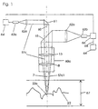
- FIG. 1 shows a microscope beam path 60a with a schematically indicated one Main lens 8 and a zoom 13. Behind the zoom 13 is essentially in Area of the optical axis 7 of the beam path 60 as a deflection element 61 Fade-in element for a light beam that is incident transversely to the optical axis 7 57c arranged.
- the holding of the deflecting element 61 is not shown since a large number of brackets are known to any person skilled in the art.
- the incident Beams of light are generated in a light source 64 and preferably by one Light guide 63a and a focusing element 62a against the deflection element 61.
- the light beam 57c preferably passes along the deflection element 61 the optical axis 7 to the object 22, where it reflects on an object detail 22a is reached and through the microscope optics 8, 13 to a second deflection element 65 and there transversely to the optical axis 7, if necessary, by a focusing element 62b and a light guide 63b is fed to a sensor 66.
- the light source 64 and sensor 66 are preferably connected to one another, in particular is a measuring system with an optical fiber output 63a and Fiber optic input 63b.
- the light source 64 supplies a modulated light with a preferably sinusoidal, but possibly triangular, periodic intensity fluctuation.
- a modulated laser is preferred, but possibly also a modulated one LED used.
- 66 there is a direct Determination of the phase shift of the modulation signal on the light path determined from the light source 64 to the sensor 66. This phase shift will made accessible to a microprocessor 44 via a line 68.
- the processor 44 determines from the phase shift of the modulation function, the modulation frequency, or the modulation wavelength and the system dimensions Distance between microscope and object.
- the microscope optics can be processed by the processor 44 be adjusted so that the field of view lies at the specified distance is coming.
- the measuring range for the entire light path is essentially a modulation wavelength. Modulation frequencies of 50 or 200 MHz result clear measuring ranges of about 6 m or 1.5 m. With a microscope it is effectively required distance area 67 in which the object can be moved and in which the distance must be measurable, very small. At the frequencies listed above the distance range 67 corresponds only to a portion of my half of the measuring range, so that the distance can be clearly determined.
- the modulation frequency be chosen as large as possible.
- the lasers known today can cannot be modulated with frequencies up to approximately 100 MHz. But it has been shown that already with a commercial, used in the field of measurement, phase-determining, "Distomat" distance measuring device from Leica AG Measurement accuracies in the range of millimeters and fractions thereof can be.
- the bundle 57c1 reflected on the object 22 diverges greatly, it can move to the side the second deflection element 65 a portion of the measurement beam 57c1 to the observer eye reach.
- the measuring beam only fails, especially after changes in position of the Microscope and / or after changes in the object surface, is emitted.
- an interval switch is also provided, which the light emission the light source 64 periodically interrupts. Because of the deflection elements 61.65 Disruptions in the microscope beam path are explanations provided in which the deflecting elements are arranged displaceably and only be moved into the microscope's beam path if necessary.
- a color filter is provided for the light source 64.
- the filter is preferably very narrow-band and just filters only the wavelength range of the measuring beam 57c1 that e.g. lies out in the infrared.
- FIG. 2 shows an embodiment in which the light source and the light sensor for the distance determination is spatially summarized in a distance measuring system 69 and from where the measuring light via light guide to the coupling or Auskoppelend Partners 63a and 63b is performed.
- Laser light is used, the Beam 57c between the object and the microscope through the first deflecting element 61 is coupled.
- the deflection element 61 is on a carrier plate 41c attached and is slightly offset from the optical axis 7.
- the am Object detail 22a reflected beam 57c1 is countered by the second deflection element 65 the fiber optic end piece 63b connected to the sensor directed the second Deflection element 65 is also on the carrier plate 41c in analogy to deflection elements 61 arranged.
- the measuring system 69 is connected to the microprocessor via at least one line 68 44 connected.
- the microprocessor 44 receives the distance information from Measuring system 69 also all microscope data.
- the adjustment device 49c for the microscope optics can be controlled and its current setting available. After determining the object distance, you can the microscope optics can be adjusted to the specific distance in an optimally focused manner. The focus can also be a desired difference above or can be set below the object distance, which is often the case with medical applications is essential.
- a magnification measuring unit 71 is provided, preferably the optical deflection of at least one by the microscope optics leading light beam.
- position determination system 72a, 72b are provided.
- the processor 44 is with the magnification measuring unit 71, the position determination system 72a, 72b and via an image data transmission module 47 with a External image data input 48 connected.
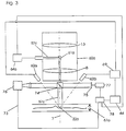
- Figure 3 shows an embodiment with an interferometer that is partially coherent Beams 57c from a light source 64a via a deflection element 61a essentially coaxial to the optical axis through a semi-transparent mirror 74 leads to object detail 22a.
- Part of the beam 57c becomes semi-transparent Beam splitter 74 across the optical axis over an adjustment path steered an adjustable reflector 75.
- the one reflected on the object and the one on the Partial beam reflected by the reflector passes through the semi-transparent beam splitter 74 under deflection, or straight, to a detector 76.
- the reflector 75 is adjusted until it forms of interference patterns in the detector plane comes to control and An evaluation of the interference measurement is an interferometer control 78 with the Detector 76, the adjusting element 77 and the laser 64a connected.
- the adjustment of the reflector 75 corresponds to a length adjustment and can be used for determination the object location can be used.
- the determined distance is from the interferometer control 78 can be fed to the processor 44 via a connection.
- the measuring range 67a of the interferometer is restricted, it is preferred another rough measuring device, in particular a distance measuring system 69 with a direct Phase measurement of a modulated signal provided.
- the light guide end pieces 63a, 63b are in the illustrated embodiment at an acute angle to optical axis 7 aligned. The measured values of the Measuring system 69 and the interferometer 73 to an extremely precise specification of distance combined.
- Fig. 4 shows schematically the measuring arrangement in connection with a microscopic Arrangement with two main lenses 8c and 8d (Greenough), without a common one Main lens.
- a measuring beam 57c passes through the coupling optics Xa from a light source X directly or via an end piece X of an intermediate one Light guide preferably parallel and symmetrical to the optical axis 7 to Object 22A.
- the stray light is a mirror 65 and decoupling optics Ya Detector Y supplied directly or an end piece Y of another light guide.
- FIG. 5 shows a laser 56 which enters the beam via an adjustable beam splitter 32a Microscope optics 8, 13 is deflected.
- the microscope optics 8, 13 get the Beam 57a via a beam splitter 4c to a measuring array 45a.
- the beam 57a can be observed through an eyepiece 18.
- To determine the magnification, or the position of the focal plane the beam positions on the measuring array 45a and the corresponding positions of the insertion element 32a are used.
- the laser is used to minimize possible interference from the measuring beam 56 controlled by an interval switch 43.
- the evaluation of the position data takes place in a microprocessor 44a.
- the components described above will connected to each other by connecting lines 50a and 50c.
- the distance is determined via a distance measuring system 69, from the light guide lead to the end pieces 63 and 63 '.
- Laser light is used, the Steel 57c between the object and the microscope against the first deflecting element 61 is fed.
- the beam reflected at the object detail 22a is from the second deflection element 65 against the light guide end piece connected to the sensor 63 'deflected
- the distance measuring system 69 is with the processor 44a connected, so that this from the distance values and the magnification values can determine real positions on the examined image section.
- FIG. 6 shows a thin glass plate 41, possibly with an anti-reflection coating or carries several small fade-in elements 4 that are so scarce on lenses, Main lenses 8 etc. can be pushed up and only partial - in usually negligible - cause optical interference.
- the in the Fade-in elements shown in other figures can be replaced by such.
- the PCT patent application is again WO-A-95 27 918.
- a variant in combination with a position detection according to the patent claims 20 to 26 of the mentioned PCT patent application is preferred.
Landscapes
- Physics & Mathematics (AREA)
- Engineering & Computer Science (AREA)
- General Physics & Mathematics (AREA)
- Electromagnetism (AREA)
- Radar, Positioning & Navigation (AREA)
- Remote Sensing (AREA)
- Computer Networks & Wireless Communication (AREA)
- General Health & Medical Sciences (AREA)
- Health & Medical Sciences (AREA)
- Surgery (AREA)
- Chemical & Material Sciences (AREA)
- Analytical Chemistry (AREA)
- Optics & Photonics (AREA)
- Microscoopes, Condenser (AREA)
- Length Measuring Devices By Optical Means (AREA)
- Electron Sources, Ion Sources (AREA)
- Measurement Of Optical Distance (AREA)
- Instruments For Measurement Of Length By Optical Means (AREA)
Description
- rein optische Mikroskope, das heisst, Mikroskope, die nur optische und mechanische Bauteile enthalten, wobei deren Ausgang dem Auge zugewandt ist; zweitens
- reine Videomikroskope, das heisst, Mikroskope, die optische, mechanische und optoelektronische Bauteile aufweisen, wobei der optische Ausgang des Mikroskopes ausschliesslich einer optoelektronischen Bildaufnahmevorrichtung (z.B. einem CCD) zugewandt ist und das aufgenommene Bild ausschliesslich elektronisch weiterverarbeitet und gegebenenfalls über ein Display dargestellt wird; und drittens
- gemischte Videomikroskope, die bauliche Merkmale der Mikroskope nach erstens und zweitens gemeinsam enthalten, das heisst, dass ein Ausgang sowohl einem visuellen Betrachter direkt als auch einer Bildaufnahmevorrichtung zugewandt ist.
Claims (15)
- Verfahren zur Ermittlung der Distanz zwischen einem Objektdetail (22a) eines mit einem Mikroskop (8) betrachteten Objektes (22) und dem Mikroskop in der Richtung der Mikroskop-Mittelachse (7), die der optischen Achse oder Beobachtungs-Symmetrieachse des Mikroskops entspricht, bei dem eine Lichtquelle (64) verwendet wird und bei dem wenigstens ein Messsignal mit einem Referenzsignal verglichen wird, wobei wenigstens das Messsignal ein Lichtbündel entlang eines Lichtweges (57c) von der Lichtquelle (64) zum Objektdetail (22a) umfasst, welches Bündel von der Lichtquelle (64) auf das Objektdetail (22a) gerichtet wird, dort reflektiert oder gestreut wird, wobei das reflektierte oder gestreute Lichtbündel wenigstens teilweise einer Empfangseinheit mit wenigstens einem Sensor (66) zugeführt wird, wobei der Lichtweg (57c) in die Nähe der Mikroskopmittelachse (7) und seine Achse wenigstens annähernd parallel dazu gelegt wird, wobei die Empfangseinheit optisch und/oder elektronisch mit der Lichtquelle (64) zur Übertragung des Referenzsignals verbunden wird, wobei das am Sensor (66) in der Empfangseinheit detektierte Licht aus dem Lichtbündel mit dem Referenzsignal verglichen und/oder zusammengeführt wird, worauf entweder aus Laufzeitunterschieden insbesondere von dem Lichtbündel überlagerten Lichtpulsen bzw. Modulationen wenigstens eine vom Unterschied der beiden Signale abhängige Grösse bestimmt wird und diese zum Ableiten der Distanz zwischen dem Mikroskop und dem Objektdetail (22a) verwendet wird und/oder aus auftretenden Interferenzen bzw. Interferenzerscheinungen in Abhängigkeit vom Interferenzkontrast der optische Wegunterschied zwischen Referenzsignal und Lichtbündel Ableiten der Distanz zwischen dem Mikroskop und dem Objektdetail (22a) verwendet wird.
- Verfahren nach Anspruch 1, wobei das von der Quelle (64) emittierte Lichtbündel zeitlich moduliert wird, in der Empfangseinheit das einfallende Licht dem Sensor (66) zugeführt wird, um die Modulation zu erkennen, worauf elektronisch direkt die Phasenverschiebung zwischen den abgehenden Lichtpulsen aus der Quelle (64) und den am Sensor (66) ankommenden Lichtpulsen gemessen wird, um daraus die entsprechende Relativlage zu ermitteln, wobei bei dieser Ermittlung vorzugsweise allfällige Lichtgeschwindigkeitsunterschiede in allfälligen Glasbauteilen des Mikroskopes als konstanter Wert rechnerisch mitberücksichtigt werden.
- Verfahren nach Anspruch 1 oder 2, wobei die Modulation bzw. Kodierung des Lichtbündels durch die vorzugsweise sinusförmige, gegebenenfalls aber dreiecksförmige. Modulation der Lichtquelle, vorzugsweise eines Lasers, gegebenenfalls aber einer LED erfolgt.
- Verfahren nach einem der vorhergehenden Ansprüche, wobei die Modulation mit einer Frequenz von mindestens 10 MHz, vorzugsweise aber zwischen 30 MHz und 200 MHz, insbesondere mit etwa 50 bis 100 MHz erfolgt.
- Verfahren nach einem der vorhergehenden Ansprüche, wobei das Lichtbündel zumindest einen Strahl umfasst, der auf einen Punkt oder gegebenenfalls sukzessive hintereinander auf mehrere Punkte am Objektdetail gerichtet wird.
- Verfahren nach einem der vorhergehenden Ansprüche, wobei das Lichtbündel zumindest einen Strahl umfasst, der eine zur Erzeugung von Interferenzmustern genügende, jedoch nach oben eingeschränkte Kohärenzlänge hat und dass die Lage des Objektdetails durch das Kohärenzabgleichen eines Interferometers bestimmt wird, wobei vorzugsweise die Speisespannung der Lichtquelle variiert wird, um dadurch eine willkürliche Veränderung der Kohärenzlänge und damit des gewünschten Empfindlichkeit zu erzielen.
- Verfahren nach einem der vorhergehenden Ansprüche, wobei zur Vergrösserung des Messbereichs zusätzlich mindestens ein Grobeinstellungs-, bzw. Grobmessschritt vorgesehen ist, der beispielsweise eine Triangulationsmessung, ein mechanisches Abtasten bzw. optisches Ablesen umfasst.
- Verfahren nach einem der vorhergehenden Ansprüche, wobei sowohl für ein moduliertes Lichtsignal eine Phasenbestimmung der Lage als auch für ein Lichtsignal, das dasselbe sein kann, ein Interferenzabgleich zur Bestimmung der Lage durchgeführt wird und die beiden Lagebestimmungen zusammen zur Relativlagenbestimmung verwendet werden.
- Verfahren nach einem der vorhergehenden Ansprüche, wobei neben der Distanzbestimmung zwischen Mikroskop und Objektdetail (22a) auch Distanz-, vorzugsweise aber Positionsbestimmungen, auf dem betrachteten Objekt (22) vorgesehen sind, die von Daten über die Fokalebene und die Vergrösserung des Mikroskopes, vorzugsweise aber auch von Positionsdaten des Mikroskopes, ausgehen, wobei zur Bestimmung der Vergrösserungsdaten die Messung der optischen Ablenkung mindestens eines durch die Mikroskopoptik führenden Lichtstrahles vorgesehen ist.
- Vorrichtung zur Ermittlung der Distanz zwischen einem Objektdetail (22a) eines mit einem Mikroskop (8) betrachteten Objektes (22) und dem Mikroskop in der Richtung der Mikroskop-Mittelachse (7), die der optischen Achse oder der Beobachtungs-Symmetrieachse des Mikroskops entspricht, mit einer Lichtquelle (64), mit wenigstens einer Einrichtung zur Erzeugung eines Messsignals und eines Referenzsignals, einer Empfangseinheit mit wenigstens einem Sensor (66) und wenigstens einer Einrichtung zum Vergleichen der beiden Signale, wobei wenigstens das Messsignal ein Lichtbündel entlang eines Lichtweges (57c) von der Lichtquelle (64) zum Objektdetail (22a) umfasst, welches Bündel von der Lichtquelle (64) auf das Objektdetail (22a) richtbar ist, um dort reflektiert oder gestreut zu werden, wobei die Empfangseinheit so angeordnet ist, daß sie wenigstens einen Teil des reflektierten oder gestreuten Lichtbündels empfängt, wobei der Lichtweg (57c) in der Nähe der Mikroskopmittelachse (7) und seine Achse wenigstens annähernd parallel dazu angeordnet ist, und wobei zur Übertragung des Referenzsignals die Empfangseinheit optisch und/oder elektronisch mit der Einrichtung zur Erzeugung des Messsignals verbunden ist, wobei im Betriebszustand das am Sensor (66) in der Empfangseinheit detektierte Licht aus dem Lichtbündel mit dem Referenzsignal verglichen und/oder zusammengeführt wird, und eine Analyseeinheit, z.B. ein Mikroprozessor (44) vorgesehen ist, deren Gestaltung bzw. dessen Programmierung entweder aus Laufzeitunterschieden, insbesondere von dem Lichtbündel überlagerten Lichtpulsen bzw. Modulationen wenigstens eine vom Unterschied der beiden Signale abhängige Grösse bestimmt und aus dieser Größe die Distanz zwischen dem Mikroskop und dem Objektdetail (22a) bestimmt und/oder aus auftretenden Interferenzen bzw. Interferenzerscheinungen in Abhängigkeit vom Interferenzkontrast aus dem optischen Wegunterschied zwischen Lichtbündel und Referenzsignal die Distanz zwischen dem Mikroskop und dem Objektdetail (22a) bestimmt.
- Vorrichtung nach Anspruch 10, wobei der Sensor (66) als Phasenbestimmungssensor ausgebildet ist und mindestens eine Grösse bestimmbar macht, die von der Phasenverschiebung zwischen von der Lichtquelle (64) emittiertem und am Sensor ankommendem Licht abhängt.
- Vorrichtung nach Anspruch 10 oder 11, wobeia) die Lichtquelle (64), bzw. ein mit der Lichtquelle (64) verbundenes Lichtleiterendstück (63a), quer zur Mikroskopmittelachse (7) angeordnet ist und im Betriebsfall ein Lichtbündel (57c) im wesentlichen gegen die Mittelachse (7) ausstrahlt,b) mindestens ein erstes Umlenkelement (61), vorzugsweise im Bereich der Mittelachse (7), so vorgesehen ist, dass zumindest ein Teil des Lichtbündels (57c) im wesentlichen parallel zur Mittelachse (7) gegen das Objekt (22) umgelenkt wird,c) mindestens ein zweites Umlenkelement (65), so vorgesehen ist, dass zumindest ein Teil des reflektierten bzw. gestreuten Lichtbündels (57c1) quer zur Mittelachse (7) gegen den Sensor (66), bzw., gegen ein mit dem Sensor (66) verbundenes Lichtleiterendstück (63b), umgelenkt wird.
- Vorrichtung nach Anspruch 12, wobei das erste und/oder das zweite Umlenkelement (61,65) zwischen dem Objekt (22) und der Mikroskopoptik (8,13), gegebenenfalls im Bereich der Mikroskopoptik (8,13), oder hinter der Mikroskopoptik (8,13) angeordnet ist, wobei gegebenenfalls wenigstens ein Glasbauteil dieser Optik (8,13) zur Vermeidung von Reflexionen bzw. Übersprechen wenigstens eine Bohrung oder wenigstens eine Blende aufweist, durch welche das Strahlenbündel lenkbar ist.
- Vorrichtung nach einem der Ansprüche 10 bis 13, wobei die Lichtquelle (64) ein Modulationselement umfasst, das eine Sinus-, oder Dreiecksschwingung mit einer Frequenz von mindestens 10 MHz, vorzugsweise aber zwischen 30 MHz und 200 MHz, insbesondere von etwa 50 bis 100 MHz erzeugt und der Phasenbestimmungssensor (66) die Phasenverschiebung der Modulationsschwingung des reflektierten Lichtbündels (57c1) direkt erfassbar macht.
- Vorrichtung nach einem der Ansprüche 10 bis 14, wobei der Sensor (66) als Zweistrahl-Interferometer (73) ausgebildet ist, durch welches die Streckenlänge eines am Objekt (22) reflektierten Laserstrahls (57c) mittels eines Interferenzabgleichs bestimmbar ist.
Applications Claiming Priority (16)
| Application Number | Priority Date | Filing Date | Title |
|---|---|---|---|
| CH109194 | 1994-04-11 | ||
| CH109294 | 1994-04-11 | ||
| CH109094 | 1994-04-11 | ||
| CH108894 | 1994-04-11 | ||
| CH1089/94 | 1994-04-11 | ||
| CH1090/94 | 1994-04-11 | ||
| CH109294 | 1994-04-11 | ||
| CH109194 | 1994-04-11 | ||
| CH108994 | 1994-04-11 | ||
| CH108994 | 1994-04-11 | ||
| CH109094 | 1994-04-11 | ||
| CH1092/94 | 1994-04-11 | ||
| CH1088/94 | 1994-04-11 | ||
| CH1091/94 | 1994-04-11 | ||
| CH108894 | 1994-04-11 | ||
| PCT/EP1995/001301 WO1995027917A1 (de) | 1994-04-11 | 1995-04-09 | Verfahren zur ermittlung der lage eines objektdetails relativ zu einem operationsmikroskop und vorrichtung dazu |
Publications (2)
| Publication Number | Publication Date |
|---|---|
| EP0801760A1 EP0801760A1 (de) | 1997-10-22 |
| EP0801760B1 true EP0801760B1 (de) | 2000-09-13 |
Family
ID=27508928
Family Applications (4)
| Application Number | Title | Priority Date | Filing Date |
|---|---|---|---|
| EP95914354A Expired - Lifetime EP0755530B1 (de) | 1994-04-11 | 1995-04-09 | Anordnung zur Positionsbestimmung eines Operationsmikroskops |
| EP97119033A Expired - Lifetime EP0822436B1 (de) | 1994-04-11 | 1995-04-09 | Verfahren zur Ermittlung von Positionsdaten und Vorrichtung für das Messen der Vergrösserung in einem optischen Strahlengang |
| EP97119034A Expired - Lifetime EP0827002B1 (de) | 1994-04-11 | 1995-04-09 | Operationsmikroskopsystem mit Datenaufbereitungseinheit |
| EP95914352A Expired - Lifetime EP0801760B1 (de) | 1994-04-11 | 1995-04-09 | Verfahren zur ermittlung der distanz zwischen einem objektdetail und einem operationsmikroskop und vorrichtung dazu |
Family Applications Before (3)
| Application Number | Title | Priority Date | Filing Date |
|---|---|---|---|
| EP95914354A Expired - Lifetime EP0755530B1 (de) | 1994-04-11 | 1995-04-09 | Anordnung zur Positionsbestimmung eines Operationsmikroskops |
| EP97119033A Expired - Lifetime EP0822436B1 (de) | 1994-04-11 | 1995-04-09 | Verfahren zur Ermittlung von Positionsdaten und Vorrichtung für das Messen der Vergrösserung in einem optischen Strahlengang |
| EP97119034A Expired - Lifetime EP0827002B1 (de) | 1994-04-11 | 1995-04-09 | Operationsmikroskopsystem mit Datenaufbereitungseinheit |
Country Status (5)
| Country | Link |
|---|---|
| US (3) | US5953114A (de) |
| EP (4) | EP0755530B1 (de) |
| JP (2) | JPH09512922A (de) |
| DE (4) | DE59510540D1 (de) |
| WO (2) | WO1995027918A2 (de) |
Families Citing this family (45)
| Publication number | Priority date | Publication date | Assignee | Title |
|---|---|---|---|---|
| EP0755530B1 (de) * | 1994-04-11 | 2000-06-07 | Leica Microsystems AG | Anordnung zur Positionsbestimmung eines Operationsmikroskops |
| US6483948B1 (en) * | 1994-12-23 | 2002-11-19 | Leica Ag | Microscope, in particular a stereomicroscope, and a method of superimposing two images |
| JPH11502037A (ja) | 1995-05-17 | 1999-02-16 | ライカ ミクロスコピー ズュステーメ アーゲー | 顕微鏡 |
| US6307636B1 (en) | 1996-11-22 | 2001-10-23 | Leica Microsystems Ag | Method for telemeasuring and telemeter |
| DE19751781C2 (de) * | 1996-11-22 | 2002-02-14 | Leica Mikroskopie Systeme Ag H | Mikroskop mit Positionsüberwachung |
| EP0910986A1 (de) * | 1997-10-24 | 1999-04-28 | BRITISH TELECOMMUNICATIONS public limited company | Bilderzeugungsapparat |
| US6671058B1 (en) | 1998-03-23 | 2003-12-30 | Leica Geosystems Ag | Method for determining the position and rotational position of an object |
| CN100390599C (zh) | 1998-06-05 | 2008-05-28 | 精工爱普生株式会社 | 光源装置和显示装置 |
| US6166506A (en) * | 1998-06-19 | 2000-12-26 | Tregaskiss, Ltd. | Wireless safety clutch |
| DE19853407C2 (de) * | 1998-11-19 | 2003-09-11 | Leica Microsystems | Verfahren zur Einstellung der Systemparameter eines konfokalen Laserscanmikroskops |
| DE19908883A1 (de) * | 1999-03-02 | 2000-09-07 | Rainer Heintzmann | Verfahren zur Erhöhung der Auflösung optischer Abbildung |
| DE10101184A1 (de) * | 2000-02-11 | 2001-08-16 | Zeiss Carl | Operationsmikroskop |
| US20020049910A1 (en) * | 2000-07-25 | 2002-04-25 | Salomon Allen Michael | Unified trust model providing secure identification, authentication and validation of physical products and entities, and processing, storage and exchange of information |
| DE50111444D1 (de) | 2000-09-28 | 2006-12-28 | Leica Microsystems Schweiz Ag | Stativ |
| DE10100335B4 (de) * | 2001-01-03 | 2017-02-09 | Carl Zeiss Meditec Ag | Vorrichtung zur Anzeige einer Größe im Blickfeld eines Benutzers und Verwendung der Vorrichtung |
| DE10121732A1 (de) * | 2001-05-04 | 2002-11-07 | Leica Microsystems | Mikroskop und Verfahren zum Betreiben eines Mikroskops |
| DE10125971A1 (de) * | 2001-05-29 | 2002-12-05 | Leica Mikroskopie Systeme Ag H | Verfahren zur Entfernungsmessung ausgedehnter Objekte in Verbindung mit einer optischen Betrachtungseinrichtung und Mikroskop zur Durchführung desselben |
| US7170677B1 (en) | 2002-01-25 | 2007-01-30 | Everest Vit | Stereo-measurement borescope with 3-D viewing |
| DE10204430A1 (de) | 2002-02-04 | 2003-08-07 | Zeiss Carl | Stereo-Mikroskopieverfahren und Stereo-Mikroskopiesystem |
| DE10226275A1 (de) * | 2002-06-06 | 2004-01-08 | Leica Microsystems (Schweiz) Ag | Verfahren zum Überlagern einer Bildfolge mit einem statischen Bild |
| DE10225193B4 (de) * | 2002-06-06 | 2004-08-12 | Leica Microsystems (Schweiz) Ag | Verfahren zur Kalibrierung der Vergrößerung eines Mikroskops sowie kalibrierbares Mikroskop |
| DE10233087A1 (de) * | 2002-07-19 | 2004-02-05 | Roche Diagnostics Gmbh | Reflexionsphotometrisches Analysesystem |
| DE10241261A1 (de) * | 2002-09-06 | 2004-03-18 | Leica Microsystems (Schweiz) Ag | Schutzbeleuchtung für Operationsmikroskope |
| DE10336476B4 (de) * | 2003-08-08 | 2007-06-06 | Carl Zeiss Surgical Gmbh | Stereo-Mikroskopiesystem |
| DE10339619A1 (de) * | 2003-08-28 | 2005-03-24 | Leica Microsystems (Schweiz) Ag | Stereomikroskop mit integrierter Auflicht-Beleuchtungseinrichtung |
| US8717553B1 (en) * | 2003-09-16 | 2014-05-06 | Apple Inc. | Positioning a first surface in a pre-determined position relative to a second surface |
| DE10355529A1 (de) * | 2003-11-21 | 2005-07-07 | Carl Zeiss Jena Gmbh | Stereomikroskop |
| US7315414B2 (en) * | 2004-03-31 | 2008-01-01 | Swift Instruments, Inc. | Microscope with adjustable stage |
| US20050219689A1 (en) * | 2004-03-31 | 2005-10-06 | Copeland David J | Microscope with retractable cord |
| US7623278B2 (en) * | 2006-09-26 | 2009-11-24 | Xerox Corporation | MEMS Fabry-Perot inline color scanner for printing applications using stationary membranes |
| US7583418B2 (en) * | 2006-09-26 | 2009-09-01 | Xerox Corporation | Array based sensor to measure single separation or mixed color (or IOI) patches on the photoreceptor using MEMS based hyperspectral imaging technology |
| US9386914B2 (en) * | 2007-04-04 | 2016-07-12 | Karl Storz Endovision, Inc. | Video endoscopic device with detachable control circuit |
| DE102008018951A1 (de) * | 2008-04-15 | 2009-10-22 | Carl Zeiss Microimaging Gmbh | Mikroskop mit Haltefokuseinheit |
| DE102009010263B4 (de) * | 2009-02-24 | 2011-01-20 | Reiner Kunz | Verfahren zur Navigation eines endoskopischen Instruments bei der technischen Endoskopie und zugehörige Vorrichtung |
| JP5389483B2 (ja) * | 2009-03-11 | 2014-01-15 | オリンパスメディカルシステムズ株式会社 | 観察装置 |
| JP5549203B2 (ja) * | 2009-12-01 | 2014-07-16 | セイコーエプソン株式会社 | 光学式位置検出装置、ハンド装置およびタッチパネル |
| JP5549204B2 (ja) * | 2009-12-01 | 2014-07-16 | セイコーエプソン株式会社 | 光学式位置検出装置、ハンド装置およびタッチパネル |
| US8270569B2 (en) * | 2010-07-11 | 2012-09-18 | Moshe Ein-Gal | Cascaded modulation system |
| DE102010039289A1 (de) * | 2010-08-12 | 2012-02-16 | Leica Microsystems (Schweiz) Ag | Mikroskopsystem |
| AT511310B1 (de) * | 2011-04-07 | 2013-05-15 | Riegl Laser Measurement Sys | Verfahren zur entfernungsmessung |
| US9194829B2 (en) * | 2012-12-28 | 2015-11-24 | Fei Company | Process for performing automated mineralogy |
| JP2015000288A (ja) * | 2013-06-18 | 2015-01-05 | キヤノン株式会社 | 被検体情報取得装置およびその制御方法ならびに音響信号取得装置およびその制御方法 |
| CN103363907A (zh) * | 2013-08-01 | 2013-10-23 | 山东大学 | 多路光栅尺信号采集测量系统 |
| DE102015115106B4 (de) | 2015-09-08 | 2017-04-20 | Carl Zeiss Meditec Ag | Operationsmikroskop |
| EP4311475A1 (de) * | 2022-07-25 | 2024-01-31 | Ellex Medical Pty. Ltd. | Vorrichtung und verfahren zur bestimmung der position eines bestimmten objekts in einem auge eines patienten und ophthalmische vorrichtung |
Citations (3)
| Publication number | Priority date | Publication date | Assignee | Title |
|---|---|---|---|---|
| DE3527245A1 (de) * | 1985-07-30 | 1987-02-12 | Adolf Friedrich Prof D Fercher | Verfahren und vorrichtung zur laengen- und positionsmessung |
| WO1995027226A2 (de) * | 1994-03-30 | 1995-10-12 | Leica Ag | Stereomikroscop |
| WO1995027918A2 (de) * | 1994-04-11 | 1995-10-19 | Leica Ag | Verfahren zur ermittlung von positionsdaten eines messpunktes und vorrichtung für das messen der vergrösserung in einem optischen strahlengang |
Family Cites Families (21)
| Publication number | Priority date | Publication date | Assignee | Title |
|---|---|---|---|---|
| US4122518A (en) * | 1976-05-17 | 1978-10-24 | The United States Of America As Represented By The Administrator Of The National Aeronautics & Space Administration | Automated clinical system for chromosome analysis |
| JPS58208610A (ja) * | 1982-05-17 | 1983-12-05 | ブリティッシュ・テクノロジー・グループ・リミテッド | 物体の表面検査装置 |
| JPS60258513A (ja) * | 1984-06-05 | 1985-12-20 | Olympus Optical Co Ltd | 測光顕微鏡システム |
| US4672559A (en) * | 1984-12-26 | 1987-06-09 | E. I. Du Pont De Nemours And Company | Method for operating a microscopical mapping system |
| US4686639A (en) * | 1985-02-07 | 1987-08-11 | Rockwell International Corporation | Free space microscope digitizing aid |
| NL8501665A (nl) * | 1985-06-10 | 1987-01-02 | Philips Nv | Optische aftasteenheid met positie- en standdetektiestelsel voor een elektromagnetisch gelagerd objektief. |
| JPS6214111A (ja) * | 1985-07-11 | 1987-01-22 | Canon Inc | 実体顕微鏡 |
| US4769698A (en) * | 1985-10-04 | 1988-09-06 | National Biomedical Research Foundation | Interactive microscopic image display system and method |
| US5098426A (en) * | 1989-02-06 | 1992-03-24 | Phoenix Laser Systems, Inc. | Method and apparatus for precision laser surgery |
| US5042949A (en) * | 1989-03-17 | 1991-08-27 | Greenberg Jeffrey S | Optical profiler for films and substrates |
| US5073857A (en) * | 1989-06-01 | 1991-12-17 | Accuron Corporation | Method and apparatus for cell analysis |
| FR2654513B1 (fr) * | 1989-11-10 | 1993-07-16 | Essilor Int | Procede et dispositif pour la determiantion des caracteristiques d'un lentille, et, notamment, de sa puissance. |
| NL9000622A (nl) * | 1990-03-17 | 1991-10-16 | Jan Greve Universiteit Twente | Voortbrengsel voor het detecteren van permanent geordende kleine deeltjes. |
| US5086401A (en) * | 1990-05-11 | 1992-02-04 | International Business Machines Corporation | Image-directed robotic system for precise robotic surgery including redundant consistency checking |
| US5279309A (en) * | 1991-06-13 | 1994-01-18 | International Business Machines Corporation | Signaling device and method for monitoring positions in a surgical operation |
| US5249581A (en) * | 1991-07-15 | 1993-10-05 | Horbal Mark T | Precision bone alignment |
| DE4134481C2 (de) * | 1991-10-18 | 1998-04-09 | Zeiss Carl Fa | Operationsmikroskop zur rechnergestützten, stereotaktischen Mikrochirurgie |
| DE4202505B4 (de) * | 1992-01-30 | 2004-04-29 | Carl Zeiss | Führungssystem zum räumlichen Positionieren eines chirurgischen Instrumentes, insbesondere eines Operationsmikroskops |
| AU3781193A (en) * | 1992-02-27 | 1993-09-13 | Phoenix Laser Systems, Inc. | Automated laser workstation for high precision surgical and industrial interventions |
| WO1995018511A1 (de) * | 1993-12-29 | 1995-07-06 | Leica Ag | Verfahren und vorrichtung zur aufzeichnung und wiedergabe von stereoskopischen videobildern |
| JPH09507349A (ja) * | 1993-12-29 | 1997-07-22 | ライカ アクチエンゲゼルシャフト | 表示装置上に立体ビデオ映像を表示するための方法及び装置 |
-
1995
- 1995-04-09 EP EP95914354A patent/EP0755530B1/de not_active Expired - Lifetime
- 1995-04-09 JP JP7526078A patent/JPH09512922A/ja active Pending
- 1995-04-09 WO PCT/EP1995/001311 patent/WO1995027918A2/de not_active Ceased
- 1995-04-09 DE DE59510540T patent/DE59510540D1/de not_active Expired - Fee Related
- 1995-04-09 US US08/722,019 patent/US5953114A/en not_active Expired - Lifetime
- 1995-04-09 EP EP97119033A patent/EP0822436B1/de not_active Expired - Lifetime
- 1995-04-09 WO PCT/EP1995/001301 patent/WO1995027917A1/de not_active Ceased
- 1995-04-09 DE DE59510912T patent/DE59510912D1/de not_active Expired - Fee Related
- 1995-04-09 JP JP7526082A patent/JPH09511579A/ja active Pending
- 1995-04-09 US US08/722,021 patent/US5841149A/en not_active Expired - Lifetime
- 1995-04-09 DE DE59508722T patent/DE59508722D1/de not_active Expired - Fee Related
- 1995-04-09 EP EP97119034A patent/EP0827002B1/de not_active Expired - Lifetime
- 1995-04-09 EP EP95914352A patent/EP0801760B1/de not_active Expired - Lifetime
- 1995-04-09 DE DE59508455T patent/DE59508455D1/de not_active Expired - Fee Related
-
1999
- 1999-02-18 US US09/252,230 patent/US6043890A/en not_active Expired - Lifetime
Patent Citations (3)
| Publication number | Priority date | Publication date | Assignee | Title |
|---|---|---|---|---|
| DE3527245A1 (de) * | 1985-07-30 | 1987-02-12 | Adolf Friedrich Prof D Fercher | Verfahren und vorrichtung zur laengen- und positionsmessung |
| WO1995027226A2 (de) * | 1994-03-30 | 1995-10-12 | Leica Ag | Stereomikroscop |
| WO1995027918A2 (de) * | 1994-04-11 | 1995-10-19 | Leica Ag | Verfahren zur ermittlung von positionsdaten eines messpunktes und vorrichtung für das messen der vergrösserung in einem optischen strahlengang |
Also Published As
| Publication number | Publication date |
|---|---|
| JPH09511579A (ja) | 1997-11-18 |
| EP0827002A3 (de) | 1998-11-04 |
| US6043890A (en) | 2000-03-28 |
| EP0822436B1 (de) | 2003-01-22 |
| EP0755530A1 (de) | 1997-01-29 |
| WO1995027918A3 (de) | 1996-03-21 |
| EP0755530B1 (de) | 2000-06-07 |
| EP0827002A2 (de) | 1998-03-04 |
| US5841149A (en) | 1998-11-24 |
| DE59510912D1 (de) | 2004-07-15 |
| EP0827002B1 (de) | 2004-06-09 |
| US5953114A (en) | 1999-09-14 |
| WO1995027917A1 (de) | 1995-10-19 |
| EP0801760A1 (de) | 1997-10-22 |
| EP0822436A3 (de) | 1998-11-04 |
| DE59508722D1 (de) | 2000-10-19 |
| JPH09512922A (ja) | 1997-12-22 |
| DE59510540D1 (de) | 2003-02-27 |
| WO1995027918A2 (de) | 1995-10-19 |
| EP0822436A2 (de) | 1998-02-04 |
| DE59508455D1 (de) | 2000-07-13 |
Similar Documents
| Publication | Publication Date | Title |
|---|---|---|
| EP0801760A1 (de) | Verfahren zur ermittlung der lage eines objektdetails relativ zu einem operationsmikroskop und vorrichtung dazu | |
| EP1959816B1 (de) | Interferometrische probenmessung | |
| EP1918754B1 (de) | Operationsmikroskop mit OCT-System | |
| EP1232377B1 (de) | Verfahren und vorrichtung zur messung optischer eigenschaften wenigstens zweier voneinander distanzierter bereiche in einem transparenten und/oder diffusiven gegenstand | |
| DE102017128158A1 (de) | Abstandsmessungsvorrichtung und Verfahren zur Messung von Abständen | |
| EP1662981B1 (de) | Messung der oberflächentopographie und wellenaberration eines linsensystems | |
| WO2005039462A1 (de) | Laserbearbeitung | |
| DE102011001083A1 (de) | Projektorvorrichtung mit Selbstkorrekturfunktion sowie Medizingerät mit der Projektorvorrichtung | |
| DE2641004A1 (de) | Vorrichtung und verfahren zur messung der hornhautkruemmung | |
| EP3182062B1 (de) | Kalibrierung eines interferometers | |
| DE102005058220A1 (de) | Interferometrische Probenmessung | |
| EP1624795B1 (de) | Verfahren und anordnung zum vermessen des vorderen augenabschnitts | |
| DE102010033249A1 (de) | Autofokussystem | |
| EP0610374B1 (de) | Verfahren zur messung der neigungen von grenzflächen in einem optischen system | |
| EP2690398B1 (de) | Vorrichtung zum Ermitteln der Lage von mechanischen Elementen | |
| DE102023109837A1 (de) | Beleuchtungsvorrichtung, Faserendoskop und Verfahren zum Ermitteln einer Übertragungseigenschaft einer Beleuchtungsfaser | |
| DE10331501B4 (de) | Justierung eines Mikroskops | |
| EP1576405A2 (de) | Kohärenzmikroskop | |
| DE102018126009B4 (de) | Verfahren und Mikroskop zur Bestimmung der Dicke eines Deck- oder Tragglases | |
| EP1238244B1 (de) | Kontrastautofokus mit drei optischen wegen | |
| DE102024117077B3 (de) | Optisches Kopplungsmodul, faseroptisches Mess- oder Untersuchungsgerät und Verfahren zum Gewährleisten einer zuverlässigen Übertragung optischer Signale zwischen einer ersten optischen Faser und einer zweiten optischen Faser | |
| DE3611030A1 (de) | Optisch positionierbare einrichtung | |
| AT500501B1 (de) | Vorrichtung zur messung von teilstrecken am auge mittels fourier-domain kurzkohärenz-interferometrie | |
| EP1243958A2 (de) | Verfahren zum Justieren eines Mikroskops und Mikroskop mit Einrichtung zum Justieren des Lichtstrahls | |
| DE102019113975B4 (de) | Verfahren und Vorrichtung zum Überwachen des Fokuszustands eines Mikroskops sowie Mikroskop |
Legal Events
| Date | Code | Title | Description |
|---|---|---|---|
| PUAI | Public reference made under article 153(3) epc to a published international application that has entered the european phase |
Free format text: ORIGINAL CODE: 0009012 |
|
| 17P | Request for examination filed |
Effective date: 19961008 |
|
| AK | Designated contracting states |
Kind code of ref document: A1 Designated state(s): CH DE FR GB LI |
|
| 17Q | First examination report despatched |
Effective date: 19971107 |
|
| RAP1 | Party data changed (applicant data changed or rights of an application transferred) |
Owner name: LEICA MIKROSKOPIE SYSTEME AG |
|
| RTI1 | Title (correction) |
Free format text: METHOD OF DETERMINING THE DISTANCE BETWEEN A FEATURE ON AN OBJECT AND A SURGICAL MICROSCOPE AND A DEVICE FOR CARRYING OUT THE METHOD |
|
| RTI1 | Title (correction) |
Free format text: METHOD OF DETERMINING THE DISTANCE BETWEEN A FEATURE ON AN OBJECT AND A SURGICAL MICROSCOPE AND A DEVICE FOR CARRYING OUT THE METHOD |
|
| GRAG | Despatch of communication of intention to grant |
Free format text: ORIGINAL CODE: EPIDOS AGRA |
|
| GRAG | Despatch of communication of intention to grant |
Free format text: ORIGINAL CODE: EPIDOS AGRA |
|
| GRAH | Despatch of communication of intention to grant a patent |
Free format text: ORIGINAL CODE: EPIDOS IGRA |
|
| GRAH | Despatch of communication of intention to grant a patent |
Free format text: ORIGINAL CODE: EPIDOS IGRA |
|
| GRAA | (expected) grant |
Free format text: ORIGINAL CODE: 0009210 |
|
| RAP1 | Party data changed (applicant data changed or rights of an application transferred) |
Owner name: LEICA MICROSYSTEMS AG |
|
| AK | Designated contracting states |
Kind code of ref document: B1 Designated state(s): CH DE FR GB LI |
|
| RIN1 | Information on inventor provided before grant (corrected) |
Inventor name: ROGERS, JOHN, RICE Inventor name: MAYER, THOMAS Inventor name: ZIMMER, KLAUS-PETER Inventor name: BRAUNECKER, BERNHARD Inventor name: SPINK, ROGER |
|
| REG | Reference to a national code |
Ref country code: CH Ref legal event code: EP |
|
| REF | Corresponds to: |
Ref document number: 59508722 Country of ref document: DE Date of ref document: 20001019 |
|
| GBT | Gb: translation of ep patent filed (gb section 77(6)(a)/1977) |
Effective date: 20001018 |
|
| ET | Fr: translation filed | ||
| PLBE | No opposition filed within time limit |
Free format text: ORIGINAL CODE: 0009261 |
|
| STAA | Information on the status of an ep patent application or granted ep patent |
Free format text: STATUS: NO OPPOSITION FILED WITHIN TIME LIMIT |
|
| 26N | No opposition filed | ||
| REG | Reference to a national code |
Ref country code: GB Ref legal event code: IF02 |
|
| PGFP | Annual fee paid to national office [announced via postgrant information from national office to epo] |
Ref country code: GB Payment date: 20050329 Year of fee payment: 11 |
|
| PGFP | Annual fee paid to national office [announced via postgrant information from national office to epo] |
Ref country code: FR Payment date: 20050412 Year of fee payment: 11 Ref country code: CH Payment date: 20050412 Year of fee payment: 11 |
|
| PG25 | Lapsed in a contracting state [announced via postgrant information from national office to epo] |
Ref country code: GB Free format text: LAPSE BECAUSE OF NON-PAYMENT OF DUE FEES Effective date: 20060409 |
|
| PG25 | Lapsed in a contracting state [announced via postgrant information from national office to epo] |
Ref country code: LI Free format text: LAPSE BECAUSE OF NON-PAYMENT OF DUE FEES Effective date: 20060430 Ref country code: CH Free format text: LAPSE BECAUSE OF NON-PAYMENT OF DUE FEES Effective date: 20060430 |
|
| REG | Reference to a national code |
Ref country code: CH Ref legal event code: PL |
|
| GBPC | Gb: european patent ceased through non-payment of renewal fee |
Effective date: 20060409 |
|
| REG | Reference to a national code |
Ref country code: FR Ref legal event code: ST Effective date: 20061230 |
|
| PG25 | Lapsed in a contracting state [announced via postgrant information from national office to epo] |
Ref country code: FR Free format text: LAPSE BECAUSE OF NON-PAYMENT OF DUE FEES Effective date: 20060502 |
|
| PGFP | Annual fee paid to national office [announced via postgrant information from national office to epo] |
Ref country code: DE Payment date: 20080418 Year of fee payment: 14 |
|
| PG25 | Lapsed in a contracting state [announced via postgrant information from national office to epo] |
Ref country code: DE Free format text: LAPSE BECAUSE OF NON-PAYMENT OF DUE FEES Effective date: 20091103 |