EP0800101A2 - Führungsblock-Baugruppe und Verfahren zur Ausrichtung von bohrungserzeugenden Stiften während Giessvorgangs von optischen Multifasersteckerstiften - Google Patents
Führungsblock-Baugruppe und Verfahren zur Ausrichtung von bohrungserzeugenden Stiften während Giessvorgangs von optischen Multifasersteckerstiften Download PDFInfo
- Publication number
- EP0800101A2 EP0800101A2 EP97302263A EP97302263A EP0800101A2 EP 0800101 A2 EP0800101 A2 EP 0800101A2 EP 97302263 A EP97302263 A EP 97302263A EP 97302263 A EP97302263 A EP 97302263A EP 0800101 A2 EP0800101 A2 EP 0800101A2
- Authority
- EP
- European Patent Office
- Prior art keywords
- fiber
- bore
- blocks
- block
- guide
- Prior art date
- Legal status (The legal status is an assumption and is not a legal conclusion. Google has not performed a legal analysis and makes no representation as to the accuracy of the status listed.)
- Withdrawn
Links
- 239000000835 fiber Substances 0.000 title claims description 158
- 238000000465 moulding Methods 0.000 title claims description 23
- 238000000034 method Methods 0.000 title abstract description 24
- 230000003287 optical effect Effects 0.000 title description 5
- 125000006850 spacer group Chemical group 0.000 claims description 19
- 238000003754 machining Methods 0.000 claims description 13
- 230000005540 biological transmission Effects 0.000 abstract description 4
- 239000013307 optical fiber Substances 0.000 description 12
- 239000000919 ceramic Substances 0.000 description 8
- 238000010276 construction Methods 0.000 description 8
- 238000004519 manufacturing process Methods 0.000 description 3
- 239000000463 material Substances 0.000 description 3
- 230000000717 retained effect Effects 0.000 description 3
- 238000007667 floating Methods 0.000 description 2
- 239000002184 metal Substances 0.000 description 2
- 238000012986 modification Methods 0.000 description 2
- 230000004048 modification Effects 0.000 description 2
- 238000007747 plating Methods 0.000 description 2
- 238000006467 substitution reaction Methods 0.000 description 2
- 229910000831 Steel Inorganic materials 0.000 description 1
- 238000013459 approach Methods 0.000 description 1
- 229910010293 ceramic material Inorganic materials 0.000 description 1
- 238000004140 cleaning Methods 0.000 description 1
- 230000003247 decreasing effect Effects 0.000 description 1
- 239000010437 gem Substances 0.000 description 1
- 229910001751 gemstone Inorganic materials 0.000 description 1
- 238000003780 insertion Methods 0.000 description 1
- 230000037431 insertion Effects 0.000 description 1
- 230000013011 mating Effects 0.000 description 1
- 238000005259 measurement Methods 0.000 description 1
- 238000005498 polishing Methods 0.000 description 1
- 230000002028 premature Effects 0.000 description 1
- 239000011347 resin Substances 0.000 description 1
- 229920005989 resin Polymers 0.000 description 1
- 238000010079 rubber tapping Methods 0.000 description 1
- 229910052594 sapphire Inorganic materials 0.000 description 1
- 239000010980 sapphire Substances 0.000 description 1
- 239000010959 steel Substances 0.000 description 1
Images


Classifications
-
- G—PHYSICS
- G02—OPTICS
- G02B—OPTICAL ELEMENTS, SYSTEMS OR APPARATUS
- G02B6/00—Light guides; Structural details of arrangements comprising light guides and other optical elements, e.g. couplings
- G02B6/24—Coupling light guides
- G02B6/36—Mechanical coupling means
- G02B6/38—Mechanical coupling means having fibre to fibre mating means
- G02B6/3807—Dismountable connectors, i.e. comprising plugs
- G02B6/3833—Details of mounting fibres in ferrules; Assembly methods; Manufacture
- G02B6/3865—Details of mounting fibres in ferrules; Assembly methods; Manufacture fabricated by using moulding techniques
-
- B—PERFORMING OPERATIONS; TRANSPORTING
- B29—WORKING OF PLASTICS; WORKING OF SUBSTANCES IN A PLASTIC STATE IN GENERAL
- B29C—SHAPING OR JOINING OF PLASTICS; SHAPING OF MATERIAL IN A PLASTIC STATE, NOT OTHERWISE PROVIDED FOR; AFTER-TREATMENT OF THE SHAPED PRODUCTS, e.g. REPAIRING
- B29C33/00—Moulds or cores; Details thereof or accessories therefor
- B29C33/30—Mounting, exchanging or centering
- B29C33/303—Mounting, exchanging or centering centering mould parts or halves, e.g. during mounting
- B29C33/304—Mounting, exchanging or centering centering mould parts or halves, e.g. during mounting centering cores
-
- B—PERFORMING OPERATIONS; TRANSPORTING
- B29—WORKING OF PLASTICS; WORKING OF SUBSTANCES IN A PLASTIC STATE IN GENERAL
- B29D—PRODUCING PARTICULAR ARTICLES FROM PLASTICS OR FROM SUBSTANCES IN A PLASTIC STATE
- B29D11/00—Producing optical elements, e.g. lenses or prisms
- B29D11/00663—Production of light guides
-
- G—PHYSICS
- G02—OPTICS
- G02B—OPTICAL ELEMENTS, SYSTEMS OR APPARATUS
- G02B6/00—Light guides; Structural details of arrangements comprising light guides and other optical elements, e.g. couplings
- G02B6/24—Coupling light guides
- G02B6/36—Mechanical coupling means
- G02B6/38—Mechanical coupling means having fibre to fibre mating means
- G02B6/3807—Dismountable connectors, i.e. comprising plugs
- G02B6/3833—Details of mounting fibres in ferrules; Assembly methods; Manufacture
- G02B6/3834—Means for centering or aligning the light guide within the ferrule
- G02B6/3838—Means for centering or aligning the light guide within the ferrule using grooves for light guides
- G02B6/3839—Means for centering or aligning the light guide within the ferrule using grooves for light guides for a plurality of light guides
-
- G—PHYSICS
- G02—OPTICS
- G02B—OPTICAL ELEMENTS, SYSTEMS OR APPARATUS
- G02B6/00—Light guides; Structural details of arrangements comprising light guides and other optical elements, e.g. couplings
- G02B6/24—Coupling light guides
- G02B6/36—Mechanical coupling means
- G02B6/38—Mechanical coupling means having fibre to fibre mating means
- G02B6/3807—Dismountable connectors, i.e. comprising plugs
- G02B6/3833—Details of mounting fibres in ferrules; Assembly methods; Manufacture
- G02B6/3854—Ferrules characterised by materials
-
- G—PHYSICS
- G02—OPTICS
- G02B—OPTICAL ELEMENTS, SYSTEMS OR APPARATUS
- G02B6/00—Light guides; Structural details of arrangements comprising light guides and other optical elements, e.g. couplings
- G02B6/24—Coupling light guides
- G02B6/36—Mechanical coupling means
- G02B6/38—Mechanical coupling means having fibre to fibre mating means
- G02B6/3807—Dismountable connectors, i.e. comprising plugs
- G02B6/3873—Connectors using guide surfaces for aligning ferrule ends, e.g. tubes, sleeves, V-grooves, rods, pins, balls
- G02B6/3885—Multicore or multichannel optical connectors, i.e. one single ferrule containing more than one fibre, e.g. ribbon type
-
- Y—GENERAL TAGGING OF NEW TECHNOLOGICAL DEVELOPMENTS; GENERAL TAGGING OF CROSS-SECTIONAL TECHNOLOGIES SPANNING OVER SEVERAL SECTIONS OF THE IPC; TECHNICAL SUBJECTS COVERED BY FORMER USPC CROSS-REFERENCE ART COLLECTIONS [XRACs] AND DIGESTS
- Y10—TECHNICAL SUBJECTS COVERED BY FORMER USPC
- Y10S—TECHNICAL SUBJECTS COVERED BY FORMER USPC CROSS-REFERENCE ART COLLECTIONS [XRACs] AND DIGESTS
- Y10S425/00—Plastic article or earthenware shaping or treating: apparatus
- Y10S425/01—Core positioning
Definitions
- the present invention relates to an apparatus and method for aligning and retaining bore forming pins that extend through a mould cavity for moulding multi-fiber optical connector ferrules.
- the present invention relates to a guide block assembly and method that retain and align each bore forming pin in a respective bore defined in a respective block.
- the present invention is directed to one aspect of the moulding process used to mould multi-fiber optical fiber ferrules of the type described in U.S. Patent No.5,214,730 to Nagasawa et al.
- the reference numerals 2, 3, 4 and 6 used in the Background of the Invention section are the same as those used in the Nagasawa patent.
- the multi-fiber ferrule is generally indicated by reference numeral 3 in Figure 1 of Nagasawa.
- the term ferrule is used herein instead of the term “plug assembly” used in Nagasawa.
- "Ferrule” is a term of art that refers to the structure that receives the end of an optical fiber or fibers and then is abutted against an opposing ferrule to precisely align optical fibers for transmission of an optical signal.
- the multi-fiber ferrule includes an array of optical fibers 2 disposed therein and guide bores 4 for receiving guide pins 6 to align two ferrules during the mating of the two ferrules.
- bore forming pins extend through the mould cavity to create the guide bores 4 and the bores that receive optical fibers 2 from ribbon cable 1.
- ribbon cable 1 is appropriately stripped and the individual fibers 2 are inserted into the fiber bores.
- Various techniques are used to fix the fibers in the moulded ferrule and then the face 5 of the ferrule and the ends of the fibers 2 are polished.
- Figure 1 herein shows a cross-section of an example V-groove geometry where fiber bore forming pins 7 and guide bore forming pins 8 are shown disposed in V-grooves 9.
- the disadvantages of this or similar open groove constructions are many.
- V-groove block is machined into a stock piece without the ability to adjust the relationship of the grooves to each other.
- One aspect of the present invention is a guide block assembly for aligning and retaining a plurality of fiber bore forming pins and at least one guide bore forming pin in precise relation to each other during moulding of a multi-fiber optical connector ferrule.
- the assembly comprises a plurality of fiber bore blocks each of which defines a fiber bore therethrough sized for retaining a fiber bore forming pin.
- the fiber bore blocks are arranged together in an array such that the fiber bores are generally parallel defining an axial direction. Adjoining surfaces are defined between adjacent fiber bore blocks in the array.
- the guide block assembly also comprises at least one guide bore block that defines a guide bore therethrough sized for retaining one of the guide bore forming pins.
- the guide bore block is assembled with the array of fiber bore blocks such that the guide bore is oriented generally parallel with the fiber bores. Adjoining surfaces are defined between the at least one guide block and adjacent fiber bore blocks.
- the fiber bore blocks may be formed by machining cylindrical ferrules into a rectilinear wafer whereby the ferrule bore is used as one of the fiber bores.
- At least one spacer block may comprise a top spacer block adjoined against the top of the array of fiber blocks, and a bottom spacer block adjoined against the bottom of the array of fiber bore blocks.
- the adjoining surfaces between adjacent fiber bore blocks and between the guide bore blocks and adjacent fiber bore blocks can be precisely machined and polished to achieve the desired relationships between successive fiber bores and between the fiber bores and the first and second guide bores in a lateral direction.
- the adjoining surfaces between the row of fiber bore blocks and top and bottom spacer blocks can also be precisely machined and polished to adjust the position of the fiber bores in a vertical direction.
- a first passageway may be defined through the first guide bore block and a second passageway may be defined at least partially into the second guide bore block, the first and second passageways being located such that when the first and second guide bore blocks are assembled with the array of fiber bore blocks the first and second passageways are aligned allowing the first and second guide bore blocks to be bolted toward each other to clamp against the row of fiber bore blocks.
- Another aspect of the present invention is a method of aligning and retaining a plurality of fiber bore forming pins and at least one guide bore forming pin in precise relation to each other during moulding of a multi-fiber ferrule.
- the method comprises the step of retaining each of the fiber bore forming pins in a respective fiber bore which is formed through a respective fiber bore block. Another step is adjoining the plurality of fiber bore blocks together in an array such that the fiber bores are parallel to each other defining an axial direction and defining adjoining surfaces between adjacent fiber bore blocks. Another step is retaining each of the guide bore forming pins in a respective guide bore which is formed through a respective guide bore block.
- Another step is adjoining the guide bore blocks to the array of fiber bore blocks such that the guide bores are parallel with the fiber bores and wherein adjoining surfaces are defined between the guide bore blocks and the array of fiber bore blocks.
- Another step is machining the adjoining surfaces between the fiber bore blocks and between the guide bore blocks and the array of fiber bore blocks such that when the fiber bore blocks and the guide bore blocks are assembled together, the desired relationships between successive fiber bores and between the fiber bores and the guide bores are achieved.
- Another aspect of the present invention is a method of manufacturing a fiber bore block for use in a guide block assembly that is used for aligning and retaining fiber bore forming pins and guide bore forming pins in precise relation to each other during moulding of a multi-fiber ferrule around such pins.
- the method comprises the step of machining in a first radial direction against a cylindrical ferrule until a first planar surface is formed along the length of the ferrule.
- the cylindrical ferrule already defines a precisely machined bore extending therethrough in the axial direction.
- Another step is machining in a second radial direction against the cylindrical ferrule until a second planar surface is formed along the length of the ferrule that is opposite of and generally parallel with the first planar surface.
- the guide block assembly comprises a plurality of fiber bore blocks.
- Each fiber bore block defines a fiber bore therethrough for retaining one of the fiber bore forming pins.
- the plurality of fiber bore blocks are assembled together in an array such that the fiber bores are generally parallel defining an axial direction and such that adjoining surfaces are defined between adjacent fiber bore blocks in the array. The adjoining surfaces are readily machinable when the fiber bore blocks are disassembled to allow precise positioning of the fiber bores relative to each other when assembled.
- the assembly and methods of the present invention allow for the more precise construction of a guide block for retaining the bore forming pins during moulding of the multi-fiber ferrules. Float of pins during the moulding process is reduced, and the use of bores eliminates the build up of flash that needs to be removed after each moulding.
- the guide block also has better wear resistance due to the frictional forces being distributed over the entire interior surface of the bores as opposed to lines of contacts as in the V-groove.
- the relationships between the fiber bores and the guide bores are adjustable during construction of the assembly to achieve the desired preciseness.
- the relationships are also adjustable after the initial assembly is constructed to respond to shifts in the relationships between bores caused by the repeated use of the guide block assembly in the moulding process.
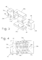
- FIG 2 partially depicts a mould cavity 12 to illustrate the environment for guide block assembly 10.
- Assembly 10 has mould face 14 which can serve as one of the walls 16 which define part of mould cavity 12.
- Making up assembly 10 is an array 20 of fiber bore blocks 22 a-h more particularly referenced in Figures 3-7.
- Guide bore blocks 24a and 24b confine array 20 in the lateral direction.
- Top spacer block 26a and bottom spacer block 26b confine array 20 in the vertical direction. It should be understood that any number and configuration of fiber bore blocks 22 can be used. For example, two rows of eight blocks or four rows of four blocks may be used.
- Assembly 10 is configured to retain a plurality of fiber bore forming pins 30 received in fiber bores 32a-h in fiber bore blocks 22a-h, respectively, and retain guide bore forming pins 33 in guide bores 34a-b in guide bore blocks 24a-b, respectively.
- Any suitable jig can be used to translate pins 30 and 33 into and out of bores 32 and 34.
- the pins are inserted into the bores and the moulding material flows around the pins. After the mould has set, the pins can be retracted to leave behind a plurality of moulded bores.
- the fiber bore forming pins will create small inner diameter moulded bores sized to receive an individual optical fiber in close tolerance.
- Fiber bore forming pins 30 may be the actual fibers when the connector will be moulded directly around the fibers.
- the guide bore forming pins will create typically larger diameter moulded bores sized to receive guide pins used to mate two opposed multi-fiber ferrules in precise alignment.
- the present invention is directed to an apparatus and method of being able to precisely arrange the fiber bore forming pins and the guide bore forming pins relative to each other in such a way that the precision is repeatable over a large number of moulding cycles.
- the method of arranging the bore forming pins with V-grooves suffers from floating of pins, flash build up, premature wear of the guide block, and the limits on preciseness of the relationships between the grooves as a result of machining the grooves in a single stock piece.
- float By using bores in an array of blocks, float is reduced, wear is reduced, flash build up is eliminated and the relationships between the bore forming pins in the bore blocks is more precise.
- bores 32 and 34 provide less room for floating of the bore forming pins 30 and 33 during the moulding process.
- the contact of the bore forming pin to the bore is spread across a larger surface area thereby decreasing wear of the bore compared to V-grooves which have only lines of contact with the bore forming pins which lend themselves to faster wear.
- FIG. 3 is a partially exploded perspective of guide block assembly 10.
- the adjoining fiber bore blocks 22a-h, guide bore blocks 24a-b, and spacer blocks 26a-b define adjoining surfaces 40 which can be precisely machined and polished.
- Each block has at least one critical distance which is defined as the distance between the centerline of the bore in such block in a normal direction to any adjoining surface 40 of such block.
- guide bore block 24a has one critical distance 42 between the centerline of guide bore 34a and adjoining surface 40 which adjoins against fiber bore block 22a.
- Distance 42 is critical because it contributes to establishing a precise relationship between guide bore 34a and the remainder of the bores. If not enough material is removed from adjoining surface 40 of guide bore block 24a in the initial construction of the blocks for a guide block assembly, then a measurement is taken of guide bore block 24a to determine the amount of machining or polishing that is needed to achieve critical distance 42. The critical distance can be precisely approached by iterations of these steps.
- guide block assembly involves iterations of machining, measuring and machining to approach the desired critical distance 42. This same methodology may be used on each critical distance 42. However, there are some short cuts that may apply to precisely constructing guide block assembly 10. For example, fiber bore blocks 22a-h may be initially machined close to the critical distance. Then, two or more of fiber bore blocks 22a-h can be rearranged in different orders in an attempt to find an order that achieves the desired preciseness of the relationship between fiber bores 32a-h.
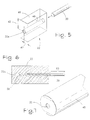
- fiber bore block 22a is generally rectilinear and defines fiber bore 32a extending therethrough in a direction defined as the axial direction.
- a representative fiber bore forming pin 30 is shown in position to be inserted into fiber bore 32a.
- Figure 6 shows a longitudinal cross-section of fiber bore block 22a with fiber bore forming pin 30 having distal end 58 disposed in fiber bore 54 and mould zone 60 of fiber bore forming pin 30 disposed outside of fiber bore block 22 where resin or plastic used in the moulding process will form around mould zone 60 of fiber bore forming pin 30.
- fiber bore block 22a has four critical distances 42 extending from the centerline of fiber bore 32a in a normal direction to each adjoining surface 40.
- fiber bore block 22a is preferably machined from commercially available cylindrical ceramic ferrule 48 which is supplied with precisely machined bore 32 as shown in Figure 7. Machining operations are applied against the ferrule in four different radial directions to create the rectilinear wafer structure of fiber bore blocks 22a-h.
- One aspect of the present invention is this method of manufacturing a fiber bore block.
- ceramic ferrule 48 may be machined to have only two or three planar surfaces. The top and/or bottom may remain arcuate with spacer blocks 26 adjoining against such arcuate surfaces.
- shims or plating techniques may be incorporated with the present invention. For example, metal shims may be placed between one or more adjoining surfaces to aid in achieving the critical distances. In such an example, either the shim, the adjoining surfaces or both may be machined to adjust the guide block assembly.
- Fiber bore blocks 22 may also be made of sapphire, other suitable jewel, or metal.
- a V-groove guide block requires that the V-grooves be machined into a piece of stock. Additionally, machining all the V-grooves into one piece of stock does not allow critical distances to be precisely obtained through iterations of machining and measuring.
- Guide bore blocks 24a, b and spacer blocks 26a, b are preferably made from hardenable mould steel.
- the guide bore blocks and spacer blocks may be eliminated from the guide block assembly.
- multifiber ferrules may be designed with a sleeve instead of guide pins to align the two ferrules. In such a case, there is no need for guide bore blocks.
- Another aspect of the present invention is a method of aligning and retaining a plurality of fiber bore forming pins and at least one guide bore forming pin generally in accordance with the operation of the guide block assembly discussed above.
- the plurality of bore forming pins are retained in fiber bores that extend through fiber bore blocks arranged in an array between two guide bore blocks.
- Two guide bore forming pins are retained in a respective guide bore formed in a respective guide bore block. All the bores are oriented parallel to each other.
- the guide bore blocks and fiber bore blocks define adjoining surfaces between adjacent blocks. The adjoining surfaces are machined such that when the blocks are assembled together, the desired relationships between successive fiber bores and between the fiber bores and the guide bores are achieved.
- FIG. 4 and 8 The various blocks of the guide block assembly can be held together in a variety of ways.
- the preferred embodiment of such attachment is shown in Figures 4 and 8.
- Four continuous passageways 70 are located as shown, each of which comprises passageway 70a bored through guide bore block 24a, passageway 70b bored through bottom spacer block 26b, and passageway 70c bored into guide bore block 24b.
- Some type of self tapping bolt 72 may be threaded through passageways 70 to pull guide bore blocks 24a and 24b toward each other thereby clamping the array of fiber bore blocks in the lateral direction.
- passageway 70c may extend through guide bore block 24b so that any type of nut and bolt arrangement can be used.
- passageways similar to passageways 70 may be located elsewhere through the blocks of the guide block assembly if more balanced clamping or bolting forces are desired.
- the blocks of guide block assembly may be retained together merely by walls 16 of the mould thereby eliminating the need for bolts 72.
- Figures 9-10 illustrate alternative block arrangements of fiber bore blocks 22 and guide bore blocks 24 with and without spacer blocks 26.
- Figure 9 does not include spacer blocks and only includes four fiber bore blocks for the moulding of a four fiber ferrule.
- Figure 10 includes one spacer block 26 underneath fiber bore blocks 22.
Landscapes
- Engineering & Computer Science (AREA)
- Mechanical Engineering (AREA)
- Physics & Mathematics (AREA)
- Health & Medical Sciences (AREA)
- Manufacturing & Machinery (AREA)
- Ophthalmology & Optometry (AREA)
- General Physics & Mathematics (AREA)
- Optics & Photonics (AREA)
- Mechanical Coupling Of Light Guides (AREA)
- Two-Way Televisions, Distribution Of Moving Picture Or The Like (AREA)
Applications Claiming Priority (2)
| Application Number | Priority Date | Filing Date | Title |
|---|---|---|---|
| US627639 | 1990-12-14 | ||
| US08/627,639 US5786002A (en) | 1996-04-04 | 1996-04-04 | Guide block assembly for aligning bore forming pins during molding of multi-fiber optical connector ferrules |
Publications (2)
| Publication Number | Publication Date |
|---|---|
| EP0800101A2 true EP0800101A2 (de) | 1997-10-08 |
| EP0800101A3 EP0800101A3 (de) | 2001-01-24 |
Family
ID=24515481
Family Applications (1)
| Application Number | Title | Priority Date | Filing Date |
|---|---|---|---|
| EP97302263A Withdrawn EP0800101A3 (de) | 1996-04-04 | 1997-04-02 | Führungsblock-Baugruppe und Verfahren zur Ausrichtung von bohrungserzeugenden Stiften während Giessvorgangs von optischen Multifasersteckerstiften |
Country Status (3)
| Country | Link |
|---|---|
| US (3) | US5786002A (de) |
| EP (1) | EP0800101A3 (de) |
| JP (1) | JPH1031135A (de) |
Cited By (2)
| Publication number | Priority date | Publication date | Assignee | Title |
|---|---|---|---|---|
| CN102248637A (zh) * | 2010-05-20 | 2011-11-23 | 鸿富锦精密工业(深圳)有限公司 | 用于成型光纤耦合连接器之模具 |
| EP2402742A2 (de) | 2007-01-19 | 2012-01-04 | Tyco Healthcare Group, LP | Stromleitfähigkeitssonden und Herstellungsverfahren dafür |
Families Citing this family (34)
| Publication number | Priority date | Publication date | Assignee | Title |
|---|---|---|---|---|
| JP4061682B2 (ja) * | 1996-12-27 | 2008-03-19 | 住友電気工業株式会社 | 光コネクタフェルールの成形方法 |
| US6338618B1 (en) | 1997-10-09 | 2002-01-15 | Lear Corporation | Apparatus for molding articles |
| CN1275210A (zh) * | 1998-08-07 | 2000-11-29 | 住友电气工业株式会社 | 光连接器用光纤套管、其成形金属模、光连接器用光纤套管的制造方法及光连接器用光纤套管的检查方法 |
| TW416014B (en) * | 1999-03-05 | 2000-12-21 | Ind Tech Res Inst | Production method of multi-fiber optical connector ferrules and forming mold |
| JP3271707B2 (ja) * | 1999-11-19 | 2002-04-08 | 財団法人工業技術研究院 | 高寸法精度の金型の製造方法および分離型光ファイバーコネクタフェルールの製造方法 |
| US6663377B1 (en) * | 2000-07-21 | 2003-12-16 | Corning Cable Systems Llc | Precision insert for molding multi-fiber connectors and method for manufacturing thereof |
| US6767199B2 (en) * | 2000-07-21 | 2004-07-27 | Corning Cable Systems Llc | Precision insert for molding multi-fiber connectors and method for manufacturing thereof |
| JP4346255B2 (ja) * | 2001-04-06 | 2009-10-21 | 古河電気工業株式会社 | 多心光コネクタフェルールの製造装置 |
| US6695488B2 (en) * | 2001-07-19 | 2004-02-24 | Cinch Connectors, Inc. | Tool and method for forming a multi fiber ferrule |
| US11243494B2 (en) | 2002-07-31 | 2022-02-08 | Abs Global, Inc. | Multiple laminar flow-based particle and cellular separation with laser steering |
| US7699767B2 (en) | 2002-07-31 | 2010-04-20 | Arryx, Inc. | Multiple laminar flow-based particle and cellular separation with laser steering |
| US6945706B2 (en) * | 2002-09-27 | 2005-09-20 | Corning Cable Systems Llc | Ferrule guide member and ferrule with precision optical fiber placement and method for assembling same |
| JP4099508B2 (ja) * | 2006-01-27 | 2008-06-11 | Tdk株式会社 | 成形用ダイス |
| US7806601B2 (en) | 2007-03-21 | 2010-10-05 | Corning Cable Systems Llc | Multifiber ferrule with precision bumpers and methods for making the same |
| US20090196563A1 (en) * | 2008-02-01 | 2009-08-06 | Mullsteff David M | Multi-Fiber Optical Patch Cord Breakout Assembly |
| CN102405429A (zh) * | 2009-03-17 | 2012-04-04 | Adc电信公司 | 在光纤电缆上直接模塑套圈的方法 |
| TW201142392A (en) * | 2010-05-20 | 2011-12-01 | Hon Hai Prec Ind Co Ltd | Mold for making optical fiber coupling connector |
| TW201206679A (en) * | 2010-08-06 | 2012-02-16 | Hon Hai Prec Ind Co Ltd | Mold for making optical fiber coupling connector |
| US10908066B2 (en) | 2010-11-16 | 2021-02-02 | 1087 Systems, Inc. | Use of vibrational spectroscopy for microfluidic liquid measurement |
| US8297963B2 (en) * | 2011-01-04 | 2012-10-30 | Teng-Jen Yang | Mould with easy-replaceable mould plates |
| US8740601B2 (en) * | 2011-08-08 | 2014-06-03 | Teng-Jen Yang | 3-plate mold assembly with a common mold base |
| US9213147B2 (en) * | 2011-11-08 | 2015-12-15 | Sabritec | Floating fiber optic pin contact assembly having a ferrule capable of movement within a multi-piece body of the contact assembly |
| WO2014011282A2 (en) * | 2012-04-11 | 2014-01-16 | Nanoprecision Products, Inc. | Hermetic optical fiber alignment assembly |
| US9897764B2 (en) | 2012-09-28 | 2018-02-20 | Commscope Technologies Llc | Molded ferrules for optical fibers |
| US8961904B2 (en) | 2013-07-16 | 2015-02-24 | Premium Genetics (Uk) Ltd. | Microfluidic chip |
| US11796449B2 (en) | 2013-10-30 | 2023-10-24 | Abs Global, Inc. | Microfluidic system and method with focused energy apparatus |
| US10180388B2 (en) | 2015-02-19 | 2019-01-15 | 1087 Systems, Inc. | Scanning infrared measurement system |
| US11331670B2 (en) | 2018-05-23 | 2022-05-17 | Abs Global, Inc. | Systems and methods for particle focusing in microchannels |
| EP3899489B1 (de) | 2018-12-21 | 2025-04-09 | ABS Global, Inc. | System und verfahren zur identifizierung einer subpopulation |
| EP3955735B1 (de) | 2019-04-18 | 2024-05-22 | ABS Global, Inc. | System und verfahren zur kontinuierlichen zugabe eines kryoprotektivums |
| US11628439B2 (en) | 2020-01-13 | 2023-04-18 | Abs Global, Inc. | Single-sheath microfluidic chip |
| WO2022087299A1 (en) | 2020-10-21 | 2022-04-28 | Abs Global, Inc. | Methods and systems for processing genetic samples to determine identity or detect contamination |
| US12135270B2 (en) | 2020-11-23 | 2024-11-05 | Abs Global, Inc. | Modular flow cytometry systems and methods of processing samples |
| USD1118965S1 (en) | 2021-11-12 | 2026-03-17 | Abs Global, Inc. | Flow cytometry device |
Family Cites Families (10)
| Publication number | Priority date | Publication date | Assignee | Title |
|---|---|---|---|---|
| US4261641A (en) * | 1979-04-02 | 1981-04-14 | The Boeing Company | Active multiport fiber optic data bus coupler |
| US4689005A (en) * | 1982-11-02 | 1987-08-25 | Polaroid Corporation | Molding apparatus |
| JPS5988710A (ja) * | 1982-11-15 | 1984-05-22 | Hitachi Ltd | プラスチツク多芯光コネクタ |
| US4951380A (en) * | 1988-06-30 | 1990-08-28 | Raytheon Company | Waveguide structures and methods of manufacture for traveling wave tubes |
| US5222168A (en) * | 1990-12-13 | 1993-06-22 | The Furukawa Electric Co., Ltd. | Method for stacking ferrules of a stacked-type optical connector and a stacked-type optical connector |
| JP3088779B2 (ja) * | 1991-05-24 | 2000-09-18 | 古河電気工業株式会社 | 光コネクタ用フェルールの成形金型 |
| TW260753B (de) * | 1992-12-03 | 1995-10-21 | Du Pont | |
| US5389312A (en) * | 1993-10-26 | 1995-02-14 | Motorola, Inc. | Method of fabricating molded optical waveguides |
| US5637264A (en) * | 1995-09-29 | 1997-06-10 | Motorola, Inc. | Method of fabricating an optical waveguide |
| US5796896A (en) * | 1996-03-14 | 1998-08-18 | Minnesota Mining And Manufacturing Company | Multi-ferrule fiber optic connector for high density backplane applications |
-
1996
- 1996-04-04 US US08/627,639 patent/US5786002A/en not_active Expired - Fee Related
-
1997
- 1997-04-02 EP EP97302263A patent/EP0800101A3/de not_active Withdrawn
- 1997-04-04 JP JP9086404A patent/JPH1031135A/ja not_active Abandoned
-
1998
- 1998-06-12 US US09/096,971 patent/US6071442A/en not_active Expired - Fee Related
-
1999
- 1999-12-01 US US09/452,672 patent/US6213750B1/en not_active Expired - Fee Related
Cited By (3)
| Publication number | Priority date | Publication date | Assignee | Title |
|---|---|---|---|---|
| EP2402742A2 (de) | 2007-01-19 | 2012-01-04 | Tyco Healthcare Group, LP | Stromleitfähigkeitssonden und Herstellungsverfahren dafür |
| CN102248637A (zh) * | 2010-05-20 | 2011-11-23 | 鸿富锦精密工业(深圳)有限公司 | 用于成型光纤耦合连接器之模具 |
| CN102248637B (zh) * | 2010-05-20 | 2014-03-26 | 鸿富锦精密工业(深圳)有限公司 | 用于成型光纤耦合连接器之模具 |
Also Published As
| Publication number | Publication date |
|---|---|
| US6071442A (en) | 2000-06-06 |
| US6213750B1 (en) | 2001-04-10 |
| EP0800101A3 (de) | 2001-01-24 |
| JPH1031135A (ja) | 1998-02-03 |
| US5786002A (en) | 1998-07-28 |
Similar Documents
| Publication | Publication Date | Title |
|---|---|---|
| EP0800101A2 (de) | Führungsblock-Baugruppe und Verfahren zur Ausrichtung von bohrungserzeugenden Stiften während Giessvorgangs von optischen Multifasersteckerstiften | |
| DE3787495T2 (de) | Ring für optisches Verbindungsstück. | |
| KR100937284B1 (ko) | 광 커넥터 페룰, 광 커넥터, 광 부품 및 광 배선 시스템 | |
| US8262380B2 (en) | Injection mold | |
| US5862281A (en) | Optical fiber connectors | |
| US20050036742A1 (en) | Molded fiber optic ferrule with integrally formed geometry features | |
| US20120014648A1 (en) | Ferrule for optical transports | |
| US7393142B2 (en) | Molded ferrule with reference surface for end face geometry measurement | |
| DE3851594T2 (de) | Verfahren und Gerät zum Abschliessen einer optischen Faser. | |
| US6663377B1 (en) | Precision insert for molding multi-fiber connectors and method for manufacturing thereof | |
| US7086847B2 (en) | Guide block assembly for molding multi-fiber connectors | |
| EP0048597A1 (de) | Verfahren zum Spritzgiessen fiberoptischer Verbinder | |
| US6257770B1 (en) | Optical connector and method of manufacturing the same | |
| EP0388642A2 (de) | Mikromechanisches Bauteil | |
| US4265514A (en) | Guide capsule for optical fiber connectors | |
| US11280963B2 (en) | Optical fiber clamp | |
| WO2000017689A1 (de) | Steckerteil für eine optische steckverbindung und verfahren zu dessen herstellung | |
| US5949937A (en) | Optical connector | |
| US7261469B1 (en) | Precision insert for molding ferrules and associated methods of manufacture | |
| JP2635189B2 (ja) | 多心光コネクタの製造方法 | |
| KR100403668B1 (ko) | 광섬유 결선장치 성형용 금형 및 이를 이용한 광섬유결선장치 제작 방법 | |
| JP2004037844A (ja) | 光コネクタ用フェルール及びその製造方法 | |
| JPH06226793A (ja) | 多心光コネクタ用フェルール製造用金型及びその製造方法 | |
| JP4276455B2 (ja) | フェルール製造用金型のコアピン支持方法及び支持装置 | |
| JP2004151737A (ja) | 光コネクタ及びその製造方法 |
Legal Events
| Date | Code | Title | Description |
|---|---|---|---|
| PUAI | Public reference made under article 153(3) epc to a published international application that has entered the european phase |
Free format text: ORIGINAL CODE: 0009012 |
|
| AK | Designated contracting states |
Kind code of ref document: A2 Designated state(s): DE FR GB IT |
|
| PUAL | Search report despatched |
Free format text: ORIGINAL CODE: 0009013 |
|
| AK | Designated contracting states |
Kind code of ref document: A3 Designated state(s): DE FR GB IT |
|
| RIC1 | Information provided on ipc code assigned before grant |
Free format text: 7G 02B 6/38 A, 7B 29D 11/00 B, 7B 29C 33/12 B, 7B 29C 33/30 B |
|
| 17P | Request for examination filed |
Effective date: 20010724 |
|
| STAA | Information on the status of an ep patent application or granted ep patent |
Free format text: STATUS: THE APPLICATION IS DEEMED TO BE WITHDRAWN |
|
| 18D | Application deemed to be withdrawn |
Effective date: 20021031 |