US11796449B2 - Microfluidic system and method with focused energy apparatus - Google Patents
Microfluidic system and method with focused energy apparatus Download PDFInfo
- Publication number
- US11796449B2 US11796449B2 US16/279,430 US201916279430A US11796449B2 US 11796449 B2 US11796449 B2 US 11796449B2 US 201916279430 A US201916279430 A US 201916279430A US 11796449 B2 US11796449 B2 US 11796449B2
- Authority
- US
- United States
- Prior art keywords
- sperm cells
- objects
- channel
- sperm
- cells
- Prior art date
- Legal status (The legal status is an assumption and is not a legal conclusion. Google has not performed a legal analysis and makes no representation as to the accuracy of the status listed.)
- Active, expires
Links
- 238000000034 method Methods 0.000 title claims abstract description 174
- 210000004027 cell Anatomy 0.000 claims abstract description 463
- 210000002593 Y chromosome Anatomy 0.000 claims abstract description 24
- 210000001766 X chromosome Anatomy 0.000 claims abstract description 23
- 241001465754 Metazoa Species 0.000 claims abstract description 22
- 239000012530 fluid Substances 0.000 claims description 277
- 235000013601 eggs Nutrition 0.000 claims description 77
- 239000000203 mixture Substances 0.000 claims description 71
- 230000009027 insemination Effects 0.000 claims description 33
- 108020004414 DNA Proteins 0.000 claims description 29
- 230000006378 damage Effects 0.000 claims description 29
- 230000008569 process Effects 0.000 claims description 29
- 241000124008 Mammalia Species 0.000 claims description 28
- 238000001514 detection method Methods 0.000 claims description 25
- 238000000926 separation method Methods 0.000 claims description 21
- 230000002068 genetic effect Effects 0.000 claims description 20
- 244000309465 heifer Species 0.000 claims description 18
- 241000283690 Bos taurus Species 0.000 claims description 17
- 210000001161 mammalian embryo Anatomy 0.000 claims description 14
- 230000004720 fertilization Effects 0.000 claims description 13
- 238000004458 analytical method Methods 0.000 claims description 12
- 238000004519 manufacturing process Methods 0.000 claims description 9
- 238000002513 implantation Methods 0.000 claims description 8
- 238000002156 mixing Methods 0.000 claims description 6
- 230000001850 reproductive effect Effects 0.000 claims description 6
- 238000000338 in vitro Methods 0.000 claims description 5
- 238000012546 transfer Methods 0.000 claims description 5
- 241000894007 species Species 0.000 claims description 4
- 102000053602 DNA Human genes 0.000 claims description 3
- 238000002347 injection Methods 0.000 claims description 3
- 239000007924 injection Substances 0.000 claims description 3
- 244000309464 bull Species 0.000 claims description 2
- 230000016087 ovulation Effects 0.000 claims description 2
- 238000012163 sequencing technique Methods 0.000 claims description 2
- 239000000523 sample Substances 0.000 description 164
- 239000000872 buffer Substances 0.000 description 111
- 230000009471 action Effects 0.000 description 83
- 239000010410 layer Substances 0.000 description 77
- 238000009652 hydrodynamic focusing Methods 0.000 description 58
- 238000005516 engineering process Methods 0.000 description 21
- 230000003287 optical effect Effects 0.000 description 20
- 238000010186 staining Methods 0.000 description 19
- 238000010304 firing Methods 0.000 description 18
- 239000000463 material Substances 0.000 description 18
- 230000001413 cellular effect Effects 0.000 description 15
- 239000000047 product Substances 0.000 description 15
- 238000007493 shaping process Methods 0.000 description 13
- 239000000243 solution Substances 0.000 description 13
- 230000007246 mechanism Effects 0.000 description 12
- 239000000126 substance Substances 0.000 description 12
- 102000002322 Egg Proteins Human genes 0.000 description 11
- 108010000912 Egg Proteins Proteins 0.000 description 11
- 239000000975 dye Substances 0.000 description 11
- 210000002969 egg yolk Anatomy 0.000 description 11
- 235000013345 egg yolk Nutrition 0.000 description 11
- 239000007789 gas Substances 0.000 description 11
- 230000015572 biosynthetic process Effects 0.000 description 10
- 238000012545 processing Methods 0.000 description 10
- 239000010902 straw Substances 0.000 description 10
- 230000001276 controlling effect Effects 0.000 description 9
- 230000005284 excitation Effects 0.000 description 9
- 230000008832 photodamage Effects 0.000 description 9
- 238000013461 design Methods 0.000 description 8
- 238000005086 pumping Methods 0.000 description 8
- 210000000582 semen Anatomy 0.000 description 8
- 230000035899 viability Effects 0.000 description 8
- 239000007983 Tris buffer Substances 0.000 description 7
- 239000000356 contaminant Substances 0.000 description 7
- 238000000684 flow cytometry Methods 0.000 description 7
- 239000002245 particle Substances 0.000 description 7
- 108090000623 proteins and genes Proteins 0.000 description 7
- LENZDBCJOHFCAS-UHFFFAOYSA-N tris Chemical compound OCC(N)(CO)CO LENZDBCJOHFCAS-UHFFFAOYSA-N 0.000 description 7
- XLYOFNOQVPJJNP-UHFFFAOYSA-N water Substances O XLYOFNOQVPJJNP-UHFFFAOYSA-N 0.000 description 7
- PEDCQBHIVMGVHV-UHFFFAOYSA-N Glycerine Chemical compound OCC(O)CO PEDCQBHIVMGVHV-UHFFFAOYSA-N 0.000 description 6
- 230000004913 activation Effects 0.000 description 6
- 239000000084 colloidal system Substances 0.000 description 6
- 239000002346 layers by function Substances 0.000 description 6
- 239000004033 plastic Substances 0.000 description 6
- 229920003023 plastic Polymers 0.000 description 6
- 230000008901 benefit Effects 0.000 description 5
- 238000009826 distribution Methods 0.000 description 5
- 230000000694 effects Effects 0.000 description 5
- 239000000989 food dye Substances 0.000 description 5
- 230000004899 motility Effects 0.000 description 5
- PRDFBSVERLRRMY-UHFFFAOYSA-N 2'-(4-ethoxyphenyl)-5-(4-methylpiperazin-1-yl)-2,5'-bibenzimidazole Chemical compound C1=CC(OCC)=CC=C1C1=NC2=CC=C(C=3NC4=CC(=CC=C4N=3)N3CCN(C)CC3)C=C2N1 PRDFBSVERLRRMY-UHFFFAOYSA-N 0.000 description 4
- CEAZRRDELHUEMR-URQXQFDESA-N Gentamicin Chemical compound O1[C@H](C(C)NC)CC[C@@H](N)[C@H]1O[C@H]1[C@H](O)[C@@H](O[C@@H]2[C@@H]([C@@H](NC)[C@@](C)(O)CO2)O)[C@H](N)C[C@@H]1N CEAZRRDELHUEMR-URQXQFDESA-N 0.000 description 4
- 229930182566 Gentamicin Natural products 0.000 description 4
- TWRXJAOTZQYOKJ-UHFFFAOYSA-L Magnesium chloride Chemical compound [Mg+2].[Cl-].[Cl-] TWRXJAOTZQYOKJ-UHFFFAOYSA-L 0.000 description 4
- WCUXLLCKKVVCTQ-UHFFFAOYSA-M Potassium chloride Chemical compound [Cl-].[K+] WCUXLLCKKVVCTQ-UHFFFAOYSA-M 0.000 description 4
- UIIMBOGNXHQVGW-UHFFFAOYSA-M Sodium bicarbonate Chemical compound [Na+].OC([O-])=O UIIMBOGNXHQVGW-UHFFFAOYSA-M 0.000 description 4
- FAPWRFPIFSIZLT-UHFFFAOYSA-M Sodium chloride Chemical compound [Na+].[Cl-] FAPWRFPIFSIZLT-UHFFFAOYSA-M 0.000 description 4
- 239000003242 anti bacterial agent Substances 0.000 description 4
- 239000012620 biological material Substances 0.000 description 4
- 210000004369 blood Anatomy 0.000 description 4
- 239000008280 blood Substances 0.000 description 4
- 230000003833 cell viability Effects 0.000 description 4
- 238000007906 compression Methods 0.000 description 4
- 230000006835 compression Effects 0.000 description 4
- 238000004590 computer program Methods 0.000 description 4
- 230000001419 dependent effect Effects 0.000 description 4
- 230000004907 flux Effects 0.000 description 4
- 229960002518 gentamicin Drugs 0.000 description 4
- 239000007788 liquid Substances 0.000 description 4
- 238000005259 measurement Methods 0.000 description 4
- 239000002609 medium Substances 0.000 description 4
- 239000012528 membrane Substances 0.000 description 4
- 230000004048 modification Effects 0.000 description 4
- 238000012986 modification Methods 0.000 description 4
- 230000035945 sensitivity Effects 0.000 description 4
- 230000035939 shock Effects 0.000 description 4
- 230000001960 triggered effect Effects 0.000 description 4
- 238000001712 DNA sequencing Methods 0.000 description 3
- 239000004606 Fillers/Extenders Substances 0.000 description 3
- 238000003559 RNA-seq method Methods 0.000 description 3
- HEMHJVSKTPXQMS-UHFFFAOYSA-M Sodium hydroxide Chemical compound [OH-].[Na+] HEMHJVSKTPXQMS-UHFFFAOYSA-M 0.000 description 3
- 238000002835 absorbance Methods 0.000 description 3
- 229940088710 antibiotic agent Drugs 0.000 description 3
- 230000001580 bacterial effect Effects 0.000 description 3
- 230000030833 cell death Effects 0.000 description 3
- 230000008859 change Effects 0.000 description 3
- KRKNYBCHXYNGOX-UHFFFAOYSA-N citric acid Chemical compound OC(=O)CC(O)(C(O)=O)CC(O)=O KRKNYBCHXYNGOX-UHFFFAOYSA-N 0.000 description 3
- 150000001875 compounds Chemical class 0.000 description 3
- 238000010276 construction Methods 0.000 description 3
- 230000035558 fertility Effects 0.000 description 3
- 238000001914 filtration Methods 0.000 description 3
- 230000006870 function Effects 0.000 description 3
- 239000011521 glass Substances 0.000 description 3
- PCHJSUWPFVWCPO-UHFFFAOYSA-N gold Chemical compound [Au] PCHJSUWPFVWCPO-UHFFFAOYSA-N 0.000 description 3
- 239000010931 gold Substances 0.000 description 3
- 229910052737 gold Inorganic materials 0.000 description 3
- 238000010438 heat treatment Methods 0.000 description 3
- 238000005286 illumination Methods 0.000 description 3
- 238000003384 imaging method Methods 0.000 description 3
- 238000001746 injection moulding Methods 0.000 description 3
- 239000002105 nanoparticle Substances 0.000 description 3
- 239000008188 pellet Substances 0.000 description 3
- 238000006116 polymerization reaction Methods 0.000 description 3
- 238000003908 quality control method Methods 0.000 description 3
- 238000009877 rendering Methods 0.000 description 3
- 239000002356 single layer Substances 0.000 description 3
- 238000003860 storage Methods 0.000 description 3
- 239000000725 suspension Substances 0.000 description 3
- 238000013519 translation Methods 0.000 description 3
- 238000011144 upstream manufacturing Methods 0.000 description 3
- 238000005406 washing Methods 0.000 description 3
- IJGRMHOSHXDMSA-UHFFFAOYSA-N Atomic nitrogen Chemical compound N#N IJGRMHOSHXDMSA-UHFFFAOYSA-N 0.000 description 2
- 241000894006 Bacteria Species 0.000 description 2
- 240000001829 Catharanthus roseus Species 0.000 description 2
- VEXZGXHMUGYJMC-UHFFFAOYSA-N Hydrochloric acid Chemical compound Cl VEXZGXHMUGYJMC-UHFFFAOYSA-N 0.000 description 2
- 239000012901 Milli-Q water Substances 0.000 description 2
- 108091093105 Nuclear DNA Proteins 0.000 description 2
- 108091034117 Oligonucleotide Proteins 0.000 description 2
- LCTONWCANYUPML-UHFFFAOYSA-N Pyruvic acid Chemical compound CC(=O)C(O)=O LCTONWCANYUPML-UHFFFAOYSA-N 0.000 description 2
- 230000003213 activating effect Effects 0.000 description 2
- 239000000654 additive Substances 0.000 description 2
- 239000011324 bead Substances 0.000 description 2
- 230000003115 biocidal effect Effects 0.000 description 2
- 230000005540 biological transmission Effects 0.000 description 2
- 210000001772 blood platelet Anatomy 0.000 description 2
- 244000309466 calf Species 0.000 description 2
- 210000000170 cell membrane Anatomy 0.000 description 2
- 230000004700 cellular uptake Effects 0.000 description 2
- 238000005119 centrifugation Methods 0.000 description 2
- 238000011109 contamination Methods 0.000 description 2
- 230000004069 differentiation Effects 0.000 description 2
- 238000006471 dimerization reaction Methods 0.000 description 2
- 201000010099 disease Diseases 0.000 description 2
- 208000037265 diseases, disorders, signs and symptoms Diseases 0.000 description 2
- 239000003814 drug Substances 0.000 description 2
- 238000005538 encapsulation Methods 0.000 description 2
- 210000003743 erythrocyte Anatomy 0.000 description 2
- 229920000295 expanded polytetrafluoroethylene Polymers 0.000 description 2
- 238000007710 freezing Methods 0.000 description 2
- 230000008014 freezing Effects 0.000 description 2
- 230000002209 hydrophobic effect Effects 0.000 description 2
- 230000003116 impacting effect Effects 0.000 description 2
- 238000010348 incorporation Methods 0.000 description 2
- JVTAAEKCZFNVCJ-UHFFFAOYSA-N lactic acid Chemical compound CC(O)C(O)=O JVTAAEKCZFNVCJ-UHFFFAOYSA-N 0.000 description 2
- 238000000651 laser trapping Methods 0.000 description 2
- 210000000265 leukocyte Anatomy 0.000 description 2
- 150000002632 lipids Chemical class 0.000 description 2
- 238000004020 luminiscence type Methods 0.000 description 2
- 229910001629 magnesium chloride Inorganic materials 0.000 description 2
- 210000000287 oocyte Anatomy 0.000 description 2
- 239000013307 optical fiber Substances 0.000 description 2
- 210000003463 organelle Anatomy 0.000 description 2
- 230000002186 photoactivation Effects 0.000 description 2
- 239000001103 potassium chloride Substances 0.000 description 2
- 235000011164 potassium chloride Nutrition 0.000 description 2
- 230000000750 progressive effect Effects 0.000 description 2
- 230000001681 protective effect Effects 0.000 description 2
- 102000004169 proteins and genes Human genes 0.000 description 2
- 150000003839 salts Chemical class 0.000 description 2
- 238000013515 script Methods 0.000 description 2
- 210000003765 sex chromosome Anatomy 0.000 description 2
- 239000011734 sodium Substances 0.000 description 2
- 229910000030 sodium bicarbonate Inorganic materials 0.000 description 2
- 239000011780 sodium chloride Substances 0.000 description 2
- 238000004611 spectroscopical analysis Methods 0.000 description 2
- 210000000130 stem cell Anatomy 0.000 description 2
- 238000003756 stirring Methods 0.000 description 2
- 239000004094 surface-active agent Substances 0.000 description 2
- 238000010257 thawing Methods 0.000 description 2
- 210000004291 uterus Anatomy 0.000 description 2
- 230000003612 virological effect Effects 0.000 description 2
- 230000000007 visual effect Effects 0.000 description 2
- JKMHFZQWWAIEOD-UHFFFAOYSA-N 2-[4-(2-hydroxyethyl)piperazin-1-yl]ethanesulfonic acid Chemical compound OCC[NH+]1CCN(CCS([O-])(=O)=O)CC1 JKMHFZQWWAIEOD-UHFFFAOYSA-N 0.000 description 1
- 229910000838 Al alloy Inorganic materials 0.000 description 1
- 108091003079 Bovine Serum Albumin Proteins 0.000 description 1
- LKDRXBCSQODPBY-VRPWFDPXSA-N D-fructopyranose Chemical compound OCC1(O)OC[C@@H](O)[C@@H](O)[C@@H]1O LKDRXBCSQODPBY-VRPWFDPXSA-N 0.000 description 1
- 102000004190 Enzymes Human genes 0.000 description 1
- 108090000790 Enzymes Proteins 0.000 description 1
- 239000004593 Epoxy Substances 0.000 description 1
- LFQSCWFLJHTTHZ-UHFFFAOYSA-N Ethanol Chemical compound CCO LFQSCWFLJHTTHZ-UHFFFAOYSA-N 0.000 description 1
- 229930091371 Fructose Natural products 0.000 description 1
- RFSUNEUAIZKAJO-ARQDHWQXSA-N Fructose Chemical compound OC[C@H]1O[C@](O)(CO)[C@@H](O)[C@@H]1O RFSUNEUAIZKAJO-ARQDHWQXSA-N 0.000 description 1
- 239000005715 Fructose Substances 0.000 description 1
- WQZGKKKJIJFFOK-GASJEMHNSA-N Glucose Natural products OC[C@H]1OC(O)[C@H](O)[C@@H](O)[C@@H]1O WQZGKKKJIJFFOK-GASJEMHNSA-N 0.000 description 1
- 239000007995 HEPES buffer Substances 0.000 description 1
- 102000002812 Heat-Shock Proteins Human genes 0.000 description 1
- 108010004889 Heat-Shock Proteins Proteins 0.000 description 1
- HTTJABKRGRZYRN-UHFFFAOYSA-N Heparin Chemical compound OC1C(NC(=O)C)C(O)OC(COS(O)(=O)=O)C1OC1C(OS(O)(=O)=O)C(O)C(OC2C(C(OS(O)(=O)=O)C(OC3C(C(O)C(O)C(O3)C(O)=O)OS(O)(=O)=O)C(CO)O2)NS(O)(=O)=O)C(C(O)=O)O1 HTTJABKRGRZYRN-UHFFFAOYSA-N 0.000 description 1
- JVTAAEKCZFNVCJ-UHFFFAOYSA-M Lactate Chemical compound CC(O)C([O-])=O JVTAAEKCZFNVCJ-UHFFFAOYSA-M 0.000 description 1
- 108091028043 Nucleic acid sequence Proteins 0.000 description 1
- 241001494479 Pecora Species 0.000 description 1
- CZPWVGJYEJSRLH-UHFFFAOYSA-N Pyrimidine Chemical compound C1=CN=CN=C1 CZPWVGJYEJSRLH-UHFFFAOYSA-N 0.000 description 1
- LCTONWCANYUPML-UHFFFAOYSA-M Pyruvate Chemical compound CC(=O)C([O-])=O LCTONWCANYUPML-UHFFFAOYSA-M 0.000 description 1
- 241000700605 Viruses Species 0.000 description 1
- JLCPHMBAVCMARE-UHFFFAOYSA-N [3-[[3-[[3-[[3-[[3-[[3-[[3-[[3-[[3-[[3-[[3-[[5-(2-amino-6-oxo-1H-purin-9-yl)-3-[[3-[[3-[[3-[[3-[[3-[[5-(2-amino-6-oxo-1H-purin-9-yl)-3-[[5-(2-amino-6-oxo-1H-purin-9-yl)-3-hydroxyoxolan-2-yl]methoxy-hydroxyphosphoryl]oxyoxolan-2-yl]methoxy-hydroxyphosphoryl]oxy-5-(5-methyl-2,4-dioxopyrimidin-1-yl)oxolan-2-yl]methoxy-hydroxyphosphoryl]oxy-5-(6-aminopurin-9-yl)oxolan-2-yl]methoxy-hydroxyphosphoryl]oxy-5-(6-aminopurin-9-yl)oxolan-2-yl]methoxy-hydroxyphosphoryl]oxy-5-(6-aminopurin-9-yl)oxolan-2-yl]methoxy-hydroxyphosphoryl]oxy-5-(6-aminopurin-9-yl)oxolan-2-yl]methoxy-hydroxyphosphoryl]oxyoxolan-2-yl]methoxy-hydroxyphosphoryl]oxy-5-(5-methyl-2,4-dioxopyrimidin-1-yl)oxolan-2-yl]methoxy-hydroxyphosphoryl]oxy-5-(4-amino-2-oxopyrimidin-1-yl)oxolan-2-yl]methoxy-hydroxyphosphoryl]oxy-5-(5-methyl-2,4-dioxopyrimidin-1-yl)oxolan-2-yl]methoxy-hydroxyphosphoryl]oxy-5-(5-methyl-2,4-dioxopyrimidin-1-yl)oxolan-2-yl]methoxy-hydroxyphosphoryl]oxy-5-(6-aminopurin-9-yl)oxolan-2-yl]methoxy-hydroxyphosphoryl]oxy-5-(6-aminopurin-9-yl)oxolan-2-yl]methoxy-hydroxyphosphoryl]oxy-5-(4-amino-2-oxopyrimidin-1-yl)oxolan-2-yl]methoxy-hydroxyphosphoryl]oxy-5-(4-amino-2-oxopyrimidin-1-yl)oxolan-2-yl]methoxy-hydroxyphosphoryl]oxy-5-(4-amino-2-oxopyrimidin-1-yl)oxolan-2-yl]methoxy-hydroxyphosphoryl]oxy-5-(6-aminopurin-9-yl)oxolan-2-yl]methoxy-hydroxyphosphoryl]oxy-5-(4-amino-2-oxopyrimidin-1-yl)oxolan-2-yl]methyl [5-(6-aminopurin-9-yl)-2-(hydroxymethyl)oxolan-3-yl] hydrogen phosphate Polymers Cc1cn(C2CC(OP(O)(=O)OCC3OC(CC3OP(O)(=O)OCC3OC(CC3O)n3cnc4c3nc(N)[nH]c4=O)n3cnc4c3nc(N)[nH]c4=O)C(COP(O)(=O)OC3CC(OC3COP(O)(=O)OC3CC(OC3COP(O)(=O)OC3CC(OC3COP(O)(=O)OC3CC(OC3COP(O)(=O)OC3CC(OC3COP(O)(=O)OC3CC(OC3COP(O)(=O)OC3CC(OC3COP(O)(=O)OC3CC(OC3COP(O)(=O)OC3CC(OC3COP(O)(=O)OC3CC(OC3COP(O)(=O)OC3CC(OC3COP(O)(=O)OC3CC(OC3COP(O)(=O)OC3CC(OC3COP(O)(=O)OC3CC(OC3COP(O)(=O)OC3CC(OC3COP(O)(=O)OC3CC(OC3COP(O)(=O)OC3CC(OC3CO)n3cnc4c(N)ncnc34)n3ccc(N)nc3=O)n3cnc4c(N)ncnc34)n3ccc(N)nc3=O)n3ccc(N)nc3=O)n3ccc(N)nc3=O)n3cnc4c(N)ncnc34)n3cnc4c(N)ncnc34)n3cc(C)c(=O)[nH]c3=O)n3cc(C)c(=O)[nH]c3=O)n3ccc(N)nc3=O)n3cc(C)c(=O)[nH]c3=O)n3cnc4c3nc(N)[nH]c4=O)n3cnc4c(N)ncnc34)n3cnc4c(N)ncnc34)n3cnc4c(N)ncnc34)n3cnc4c(N)ncnc34)O2)c(=O)[nH]c1=O JLCPHMBAVCMARE-UHFFFAOYSA-N 0.000 description 1
- 238000002679 ablation Methods 0.000 description 1
- 238000010521 absorption reaction Methods 0.000 description 1
- 230000002776 aggregation Effects 0.000 description 1
- 238000004220 aggregation Methods 0.000 description 1
- 230000004075 alteration Effects 0.000 description 1
- 239000012491 analyte Substances 0.000 description 1
- 239000012984 antibiotic solution Substances 0.000 description 1
- 238000013459 approach Methods 0.000 description 1
- 238000003491 array Methods 0.000 description 1
- 238000003556 assay Methods 0.000 description 1
- QVGXLLKOCUKJST-UHFFFAOYSA-N atomic oxygen Chemical compound [O] QVGXLLKOCUKJST-UHFFFAOYSA-N 0.000 description 1
- 239000012472 biological sample Substances 0.000 description 1
- 210000001109 blastomere Anatomy 0.000 description 1
- 239000006161 blood agar Substances 0.000 description 1
- 210000001185 bone marrow Anatomy 0.000 description 1
- 229940098773 bovine serum albumin Drugs 0.000 description 1
- 238000004422 calculation algorithm Methods 0.000 description 1
- 230000005779 cell damage Effects 0.000 description 1
- 208000037887 cell injury Diseases 0.000 description 1
- 230000009087 cell motility Effects 0.000 description 1
- 230000007248 cellular mechanism Effects 0.000 description 1
- 238000000701 chemical imaging Methods 0.000 description 1
- 238000006243 chemical reaction Methods 0.000 description 1
- 239000003795 chemical substances by application Substances 0.000 description 1
- 210000000349 chromosome Anatomy 0.000 description 1
- 230000001427 coherent effect Effects 0.000 description 1
- 239000003086 colorant Substances 0.000 description 1
- 238000004891 communication Methods 0.000 description 1
- 230000003750 conditioning effect Effects 0.000 description 1
- 238000011437 continuous method Methods 0.000 description 1
- 238000010924 continuous production Methods 0.000 description 1
- 238000001816 cooling Methods 0.000 description 1
- 238000004132 cross linking Methods 0.000 description 1
- 238000005138 cryopreservation Methods 0.000 description 1
- 239000013078 crystal Substances 0.000 description 1
- 230000002950 deficient Effects 0.000 description 1
- 238000004925 denaturation Methods 0.000 description 1
- 230000036425 denaturation Effects 0.000 description 1
- 230000001627 detrimental effect Effects 0.000 description 1
- 238000011161 development Methods 0.000 description 1
- 238000010586 diagram Methods 0.000 description 1
- 238000000502 dialysis Methods 0.000 description 1
- 238000000811 diffusing wave spectroscopy Methods 0.000 description 1
- BNIILDVGGAEEIG-UHFFFAOYSA-L disodium hydrogen phosphate Chemical compound [Na+].[Na+].OP([O-])([O-])=O BNIILDVGGAEEIG-UHFFFAOYSA-L 0.000 description 1
- 229910000397 disodium phosphate Inorganic materials 0.000 description 1
- 229940079593 drug Drugs 0.000 description 1
- 238000012377 drug delivery Methods 0.000 description 1
- 238000002296 dynamic light scattering Methods 0.000 description 1
- 230000001094 effect on targets Effects 0.000 description 1
- 230000005684 electric field Effects 0.000 description 1
- 239000003792 electrolyte Substances 0.000 description 1
- 230000005672 electromagnetic field Effects 0.000 description 1
- 230000005670 electromagnetic radiation Effects 0.000 description 1
- 238000004520 electroporation Methods 0.000 description 1
- 230000008030 elimination Effects 0.000 description 1
- 238000003379 elimination reaction Methods 0.000 description 1
- 238000004049 embossing Methods 0.000 description 1
- 210000002257 embryonic structure Anatomy 0.000 description 1
- 230000007613 environmental effect Effects 0.000 description 1
- 238000000605 extraction Methods 0.000 description 1
- 230000002349 favourable effect Effects 0.000 description 1
- 238000011049 filling Methods 0.000 description 1
- 239000012467 final product Substances 0.000 description 1
- 239000007850 fluorescent dye Substances 0.000 description 1
- 238000012632 fluorescent imaging Methods 0.000 description 1
- 235000013305 food Nutrition 0.000 description 1
- 238000009472 formulation Methods 0.000 description 1
- 230000004927 fusion Effects 0.000 description 1
- 239000000499 gel Substances 0.000 description 1
- 238000001476 gene delivery Methods 0.000 description 1
- 210000004602 germ cell Anatomy 0.000 description 1
- 239000011491 glass wool Substances 0.000 description 1
- 239000008103 glucose Substances 0.000 description 1
- 229960002897 heparin Drugs 0.000 description 1
- 229920000669 heparin Polymers 0.000 description 1
- 244000144980 herd Species 0.000 description 1
- 238000000920 holographic laser trapping Methods 0.000 description 1
- 230000006872 improvement Effects 0.000 description 1
- 238000011534 incubation Methods 0.000 description 1
- 208000021267 infertility disease Diseases 0.000 description 1
- 238000003780 insertion Methods 0.000 description 1
- 230000037431 insertion Effects 0.000 description 1
- 230000003834 intracellular effect Effects 0.000 description 1
- 230000006662 intracellular pathway Effects 0.000 description 1
- 230000031146 intracellular signal transduction Effects 0.000 description 1
- 238000002955 isolation Methods 0.000 description 1
- 238000005304 joining Methods 0.000 description 1
- 210000003734 kidney Anatomy 0.000 description 1
- 239000004310 lactic acid Substances 0.000 description 1
- 235000014655 lactic acid Nutrition 0.000 description 1
- DWPCPZJAHOETAG-UHFFFAOYSA-N lanthionine Chemical compound OC(=O)C(N)CSCC(N)C(O)=O DWPCPZJAHOETAG-UHFFFAOYSA-N 0.000 description 1
- 238000000608 laser ablation Methods 0.000 description 1
- 230000031700 light absorption Effects 0.000 description 1
- 239000004973 liquid crystal related substance Substances 0.000 description 1
- 238000011068 loading method Methods 0.000 description 1
- 239000011159 matrix material Substances 0.000 description 1
- -1 media Substances 0.000 description 1
- 239000007769 metal material Substances 0.000 description 1
- 244000005700 microbiome Species 0.000 description 1
- 230000005012 migration Effects 0.000 description 1
- 238000013508 migration Methods 0.000 description 1
- 230000008437 mitochondrial biogenesis Effects 0.000 description 1
- 210000000947 motile cell Anatomy 0.000 description 1
- 239000002071 nanotube Substances 0.000 description 1
- 229910052757 nitrogen Inorganic materials 0.000 description 1
- 239000002773 nucleotide Substances 0.000 description 1
- 125000003729 nucleotide group Chemical group 0.000 description 1
- 235000015097 nutrients Nutrition 0.000 description 1
- 238000013021 overheating Methods 0.000 description 1
- 210000004681 ovum Anatomy 0.000 description 1
- 239000001301 oxygen Substances 0.000 description 1
- 229910052760 oxygen Inorganic materials 0.000 description 1
- 239000012466 permeate Substances 0.000 description 1
- 230000003300 photodamaging effect Effects 0.000 description 1
- 238000000206 photolithography Methods 0.000 description 1
- 230000000704 physical effect Effects 0.000 description 1
- 239000002985 plastic film Substances 0.000 description 1
- 230000010287 polarization Effects 0.000 description 1
- 229920000642 polymer Polymers 0.000 description 1
- 239000002861 polymer material Substances 0.000 description 1
- 229920001296 polysiloxane Polymers 0.000 description 1
- 239000011148 porous material Substances 0.000 description 1
- 230000003334 potential effect Effects 0.000 description 1
- 238000002360 preparation method Methods 0.000 description 1
- 238000004321 preservation Methods 0.000 description 1
- 229940076788 pyruvate Drugs 0.000 description 1
- 229940107700 pyruvic acid Drugs 0.000 description 1
- 230000005855 radiation Effects 0.000 description 1
- 238000004064 recycling Methods 0.000 description 1
- 230000009467 reduction Effects 0.000 description 1
- 230000001105 regulatory effect Effects 0.000 description 1
- 230000008439 repair process Effects 0.000 description 1
- 230000010076 replication Effects 0.000 description 1
- 238000011160 research Methods 0.000 description 1
- 230000004044 response Effects 0.000 description 1
- 239000005060 rubber Substances 0.000 description 1
- 238000000790 scattering method Methods 0.000 description 1
- 238000007789 sealing Methods 0.000 description 1
- 239000013049 sediment Substances 0.000 description 1
- 238000001338 self-assembly Methods 0.000 description 1
- 230000014639 sexual reproduction Effects 0.000 description 1
- 230000011664 signaling Effects 0.000 description 1
- 235000017557 sodium bicarbonate Nutrition 0.000 description 1
- PUZPDOWCWNUUKD-UHFFFAOYSA-M sodium fluoride Chemical compound [F-].[Na+] PUZPDOWCWNUUKD-UHFFFAOYSA-M 0.000 description 1
- 239000001488 sodium phosphate Substances 0.000 description 1
- 229910000162 sodium phosphate Inorganic materials 0.000 description 1
- 239000007787 solid Substances 0.000 description 1
- 238000001179 sorption measurement Methods 0.000 description 1
- 238000001228 spectrum Methods 0.000 description 1
- 230000008010 sperm capacitation Effects 0.000 description 1
- 230000000087 stabilizing effect Effects 0.000 description 1
- 239000011550 stock solution Substances 0.000 description 1
- 238000006467 substitution reaction Methods 0.000 description 1
- 239000006228 supernatant Substances 0.000 description 1
- 239000006188 syrup Substances 0.000 description 1
- 235000020357 syrup Nutrition 0.000 description 1
- 230000008685 targeting Effects 0.000 description 1
- 238000002560 therapeutic procedure Methods 0.000 description 1
- 229920001169 thermoplastic Polymers 0.000 description 1
- 239000004416 thermosoftening plastic Substances 0.000 description 1
- 231100000419 toxicity Toxicity 0.000 description 1
- 230000001988 toxicity Effects 0.000 description 1
- 238000013518 transcription Methods 0.000 description 1
- 230000035897 transcription Effects 0.000 description 1
- 238000002235 transmission spectroscopy Methods 0.000 description 1
- 238000011282 treatment Methods 0.000 description 1
- RYFMWSXOAZQYPI-UHFFFAOYSA-K trisodium phosphate Chemical compound [Na+].[Na+].[Na+].[O-]P([O-])([O-])=O RYFMWSXOAZQYPI-UHFFFAOYSA-K 0.000 description 1
- 229920002554 vinyl polymer Polymers 0.000 description 1
- 238000010792 warming Methods 0.000 description 1
- 239000002699 waste material Substances 0.000 description 1
Images


Classifications
-
- G—PHYSICS
- G01—MEASURING; TESTING
- G01N—INVESTIGATING OR ANALYSING MATERIALS BY DETERMINING THEIR CHEMICAL OR PHYSICAL PROPERTIES
- G01N15/00—Investigating characteristics of particles; Investigating permeability, pore-volume, or surface-area of porous materials
- G01N15/10—Investigating individual particles
- G01N15/14—Electro-optical investigation, e.g. flow cytometers
- G01N15/1484—Electro-optical investigation, e.g. flow cytometers microstructural devices
-
- B—PERFORMING OPERATIONS; TRANSPORTING
- B01—PHYSICAL OR CHEMICAL PROCESSES OR APPARATUS IN GENERAL
- B01L—CHEMICAL OR PHYSICAL LABORATORY APPARATUS FOR GENERAL USE
- B01L3/00—Containers or dishes for laboratory use, e.g. laboratory glassware; Droppers
- B01L3/50—Containers for the purpose of retaining a material to be analysed, e.g. test tubes
- B01L3/502—Containers for the purpose of retaining a material to be analysed, e.g. test tubes with fluid transport, e.g. in multi-compartment structures
- B01L3/5027—Containers for the purpose of retaining a material to be analysed, e.g. test tubes with fluid transport, e.g. in multi-compartment structures by integrated microfluidic structures, i.e. dimensions of channels and chambers are such that surface tension forces are important, e.g. lab-on-a-chip
- B01L3/502761—Containers for the purpose of retaining a material to be analysed, e.g. test tubes with fluid transport, e.g. in multi-compartment structures by integrated microfluidic structures, i.e. dimensions of channels and chambers are such that surface tension forces are important, e.g. lab-on-a-chip specially adapted for handling suspended solids or molecules independently from the bulk fluid flow, e.g. for trapping or sorting beads, for physically stretching molecules
-
- C—CHEMISTRY; METALLURGY
- C12—BIOCHEMISTRY; BEER; SPIRITS; WINE; VINEGAR; MICROBIOLOGY; ENZYMOLOGY; MUTATION OR GENETIC ENGINEERING
- C12N—MICROORGANISMS OR ENZYMES; COMPOSITIONS THEREOF; PROPAGATING, PRESERVING, OR MAINTAINING MICROORGANISMS; MUTATION OR GENETIC ENGINEERING; CULTURE MEDIA
- C12N13/00—Treatment of microorganisms or enzymes with electrical or wave energy, e.g. magnetism, sonic waves
-
- G—PHYSICS
- G01—MEASURING; TESTING
- G01N—INVESTIGATING OR ANALYSING MATERIALS BY DETERMINING THEIR CHEMICAL OR PHYSICAL PROPERTIES
- G01N1/00—Sampling; Preparing specimens for investigation
- G01N1/28—Preparing specimens for investigation including physical details of (bio-)chemical methods covered elsewhere, e.g. G01N33/50, C12Q
- G01N1/44—Sample treatment involving radiation, e.g. heat
-
- G—PHYSICS
- G01—MEASURING; TESTING
- G01N—INVESTIGATING OR ANALYSING MATERIALS BY DETERMINING THEIR CHEMICAL OR PHYSICAL PROPERTIES
- G01N15/00—Investigating characteristics of particles; Investigating permeability, pore-volume, or surface-area of porous materials
- G01N15/10—Investigating individual particles
- G01N15/14—Electro-optical investigation, e.g. flow cytometers
- G01N15/1404—Fluid conditioning in flow cytometers, e.g. flow cells; Supply; Control of flow
-
- G—PHYSICS
- G01—MEASURING; TESTING
- G01N—INVESTIGATING OR ANALYSING MATERIALS BY DETERMINING THEIR CHEMICAL OR PHYSICAL PROPERTIES
- G01N15/00—Investigating characteristics of particles; Investigating permeability, pore-volume, or surface-area of porous materials
- G01N15/10—Investigating individual particles
- G01N15/14—Electro-optical investigation, e.g. flow cytometers
- G01N15/1456—Electro-optical investigation, e.g. flow cytometers without spatial resolution of the texture or inner structure of the particle, e.g. processing of pulse signals
- G01N15/1459—Electro-optical investigation, e.g. flow cytometers without spatial resolution of the texture or inner structure of the particle, e.g. processing of pulse signals the analysis being performed on a sample stream
-
- G—PHYSICS
- G01—MEASURING; TESTING
- G01N—INVESTIGATING OR ANALYSING MATERIALS BY DETERMINING THEIR CHEMICAL OR PHYSICAL PROPERTIES
- G01N21/00—Investigating or analysing materials by the use of optical means, i.e. using sub-millimetre waves, infrared, visible or ultraviolet light
- G01N21/01—Arrangements or apparatus for facilitating the optical investigation
-
- G—PHYSICS
- G01—MEASURING; TESTING
- G01N—INVESTIGATING OR ANALYSING MATERIALS BY DETERMINING THEIR CHEMICAL OR PHYSICAL PROPERTIES
- G01N21/00—Investigating or analysing materials by the use of optical means, i.e. using sub-millimetre waves, infrared, visible or ultraviolet light
- G01N21/62—Systems in which the material investigated is excited whereby it emits light or causes a change in wavelength of the incident light
- G01N21/63—Systems in which the material investigated is excited whereby it emits light or causes a change in wavelength of the incident light optically excited
- G01N21/64—Fluorescence; Phosphorescence
- G01N21/6486—Measuring fluorescence of biological material, e.g. DNA, RNA, cells
-
- G—PHYSICS
- G01—MEASURING; TESTING
- G01N—INVESTIGATING OR ANALYSING MATERIALS BY DETERMINING THEIR CHEMICAL OR PHYSICAL PROPERTIES
- G01N33/00—Investigating or analysing materials by specific methods not covered by groups G01N1/00 - G01N31/00
- G01N33/48—Biological material, e.g. blood, urine; Haemocytometers
- G01N33/483—Physical analysis of biological material
- G01N33/4833—Physical analysis of biological material of solid biological material, e.g. tissue samples, cell cultures
-
- B—PERFORMING OPERATIONS; TRANSPORTING
- B01—PHYSICAL OR CHEMICAL PROCESSES OR APPARATUS IN GENERAL
- B01L—CHEMICAL OR PHYSICAL LABORATORY APPARATUS FOR GENERAL USE
- B01L2200/00—Solutions for specific problems relating to chemical or physical laboratory apparatus
- B01L2200/06—Fluid handling related problems
- B01L2200/0636—Focussing flows, e.g. to laminate flows
-
- B—PERFORMING OPERATIONS; TRANSPORTING
- B01—PHYSICAL OR CHEMICAL PROCESSES OR APPARATUS IN GENERAL
- B01L—CHEMICAL OR PHYSICAL LABORATORY APPARATUS FOR GENERAL USE
- B01L2200/00—Solutions for specific problems relating to chemical or physical laboratory apparatus
- B01L2200/06—Fluid handling related problems
- B01L2200/0647—Handling flowable solids, e.g. microscopic beads, cells, particles
- B01L2200/0652—Sorting or classification of particles or molecules
-
- B—PERFORMING OPERATIONS; TRANSPORTING
- B01—PHYSICAL OR CHEMICAL PROCESSES OR APPARATUS IN GENERAL
- B01L—CHEMICAL OR PHYSICAL LABORATORY APPARATUS FOR GENERAL USE
- B01L2300/00—Additional constructional details
- B01L2300/06—Auxiliary integrated devices, integrated components
- B01L2300/0627—Sensor or part of a sensor is integrated
-
- B—PERFORMING OPERATIONS; TRANSPORTING
- B01—PHYSICAL OR CHEMICAL PROCESSES OR APPARATUS IN GENERAL
- B01L—CHEMICAL OR PHYSICAL LABORATORY APPARATUS FOR GENERAL USE
- B01L2300/00—Additional constructional details
- B01L2300/08—Geometry, shape and general structure
- B01L2300/0887—Laminated structure
-
- G01N15/1409—
-
- G01N15/149—
-
- G—PHYSICS
- G01—MEASURING; TESTING
- G01N—INVESTIGATING OR ANALYSING MATERIALS BY DETERMINING THEIR CHEMICAL OR PHYSICAL PROPERTIES
- G01N15/00—Investigating characteristics of particles; Investigating permeability, pore-volume, or surface-area of porous materials
- G01N15/10—Investigating individual particles
- G01N2015/1006—Investigating individual particles for cytology
-
- G—PHYSICS
- G01—MEASURING; TESTING
- G01N—INVESTIGATING OR ANALYSING MATERIALS BY DETERMINING THEIR CHEMICAL OR PHYSICAL PROPERTIES
- G01N15/00—Investigating characteristics of particles; Investigating permeability, pore-volume, or surface-area of porous materials
- G01N15/10—Investigating individual particles
- G01N15/14—Electro-optical investigation, e.g. flow cytometers
- G01N15/1404—Fluid conditioning in flow cytometers, e.g. flow cells; Supply; Control of flow
- G01N2015/1409—Control of supply of sheaths fluid, e.g. sample injection control
-
- G—PHYSICS
- G01—MEASURING; TESTING
- G01N—INVESTIGATING OR ANALYSING MATERIALS BY DETERMINING THEIR CHEMICAL OR PHYSICAL PROPERTIES
- G01N15/00—Investigating characteristics of particles; Investigating permeability, pore-volume, or surface-area of porous materials
- G01N15/10—Investigating individual particles
- G01N15/14—Electro-optical investigation, e.g. flow cytometers
- G01N15/1404—Fluid conditioning in flow cytometers, e.g. flow cells; Supply; Control of flow
- G01N2015/1413—Hydrodynamic focussing
Definitions
- the present invention relates to a microfluidic system with an interrogation apparatus which detects and interrogates objects in a sample fluid mixture of a microfluidic chip, and a focused energy apparatus which performs an action which affects the objects.
- the interrogation apparatus interrogates the objects to determine their identity
- the focused energy apparatus is an apparatus acts on target objects.
- the focused energy apparatus is used to damage, kill, alter, disable, or destroy the targeted objects.
- Photo-damaging laser systems have utilized lasers to photodamage or kill undesired cellular objects.
- the prior art has required flow cytometers using nozzles, to interrogate and arrange the individual objects in droplet flow, and to attempt to separate and photodamage the objects as they fall into various containers—which has been difficult to achieve.
- a method and apparatus which identifies and discriminates between target objects, is continuous, has high throughput, is time and cost effective, and which causes negligible or minimal damage to the various target objects.
- an apparatus and method should have further applicability to other biological and medical areas, not just in sperm discrimination, but in the discrimination of blood and other cellular materials, including viral, cell organelle, globular structures, colloidal suspensions, and other biological materials.
- the present invention relates to a microfluidic system with an interrogation apparatus which detects and interrogates objects in a sample fluid mixture of a microfluidic chip, and a focused energy apparatus which performs an action which affects the objects.
- the interrogation apparatus interrogates the objects to determine their identity
- the focused energy apparatus is an apparatus acts on target objects.
- the focused energy apparatus is used to damage, kill, alter, disable, or destroy the targeted objects.
- an apparatus which identifies objects includes: a microfluidic chip in which are disposed a plurality of channels, including: a main fluid channel into which a sample fluid mixture of objects to be identified is introduced; a plurality of sheath fluid channels into which sheath fluids are introduced, the sheath fluids which orient the objects in the main fluid channel in a predetermined direction while still maintaining laminar flow in the main fluid channel; an interrogation apparatus which detects and interrogates the oriented objects in the main fluid channel; and a focused energy apparatus which performs an action on the objects.
- the interrogation apparatus detects and interrogates the objects to determine information about the objects.
- the information about the objects determines whether the objects are targeted by the focused energy apparatus.
- the action of the focused energy apparatus acts on the targeted objects or a region surrounding the targeted objects.
- the action on the targeted objects is to damage, disable, alter, kill or destroy the targeted objects.
- the apparatus further includes at least one output channel leading from the main fluid channel, the at least one output channel which removes the objects from the microfluidic chip.
- the at least one output channel removes both targeted and non-targeted objects from the microfluidic chip.
- the apparatus further includes a plurality of side output channels leading from the main fluid channel, the plurality of side output channels disposed on either side of the at least one output channel, the plurality of side output channels which remove the sheath fluids from the microfluidic chip.
- the plurality of sheath fluid channels includes: a first plurality of sheath fluid channels which intersect the main fluid channel at a first intersection, such that the sheath fluids compress the sample fluid mixture on at least two sides, such that the sample fluid mixture becomes a relatively smaller, narrower stream, bounded by the sheath fluids, while maintaining laminar flow in the main fluid channel.
- the plurality of sheath fluid channels further includes: a second plurality of sheath fluid channels which intersect the main fluid channel at a second intersection downstream from the first intersection, such that the sheath fluids from the second plurality of sheath fluid channels compress the sample fluid mixture in one of the at least two sides, or in two sides opposite from the at least two sides, such that the sample fluid mixture is further compressed while still maintaining laminar flow in the main fluid channel.
- the plurality of sheath fluids further comprise: a third sheath fluid channel disposed vertical to the main fluid channel at a third intersection, and disposed downstream from the second intersection, the sheath fluid from the third sheath fluid channel which further compresses the sample fluid while still maintaining laminar flow in the main fluid channel.
- the plurality of sheath fluid channels hydrodynamically focuses the objects such that the objects are oriented in a predetermined direction and disposed in a restricted core volume as the objects flow through the main fluid channel.
- the apparatus further includes an action chamber in which the interrogation apparatus interrogates the hydrodynamically focused objects in the sample fluid mixture, the action chamber disposed in the microfluidic chip downstream from at least one of the second intersection or the third intersection.
- the interrogation apparatus includes: a light source which emits a light beam into the action chamber, to illuminate and excite the objects in the sample fluid mixture.
- the light beam excites fluorescence in the objects such that the targeted objects are distinguished from the non-targeted objects.
- the light source is a laser.
- the apparatus further includes an optical signal detector which detects the light beam and converts it into an electronic signal; and a controller, which analyzes the electronic signal to determine whether the objects are to be targeted or non-targeted.
- the focused energy apparatus is a laser.
- the microfluidic chip contains one or more structural layers or planes.
- the main fluid channel is disposed in a different structural layer or plane from the plurality of sheath channels.
- the at least one of the sample input channel and the plurality of sheath channels are disposed in-between the structural layers or the planes of the microfluidic chip.
- the first plurality of sheath channels is disposed in a different structural layer or plane from the second plurality of sheath channels.
- the action chamber includes a first opening cut through at least one of the structural layers or the planes in the microfluidic chip, the first opening which is configured to receive a first transparent covering.
- the action chamber includes a second opening cut through the at least one of the structural layers or the planes on an opposite side of the microfluidic chip from the first opening, the second opening which is configured to receive a second transparent covering.
- the microfluidic chip contains at least one functional layer which includes the plurality of sheath fluid channels and the main fluid channel, and a top layer which contains holes to access the at least one functional layer.
- a size of one of the second plurality of sheath fluid channels is different from another of the second plurality of sheath channels.
- the size of the second plurality of sheath channels is different from a size of the first plurality of sheath channels.
- the apparatus further includes a first output disposed at an end of the at least one output channel.
- the apparatus further includes a plurality of outputs disposed at an end of each of the plurality of side output channels.
- the apparatus further includes at least one notch disposed in the microfluidic chip, the at least one notch provided between outputs.
- a size of the plurality of side output channels increases from a size of the main fluid channel.
- the main fluid channel tapers at an entry point into the first intersection in the microfluidic chip.
- the main fluid channel tapers into the action chamber.
- the second plurality of sheath channels tapers before joining the main fluid channel.
- the second plurality of sheath channels includes at least a first vertical portion which joins the main fluid channel from approximately a right angle above the main fluid channel.
- the second plurality of sheath channels includes a second vertical portion which joins the main fluid channel from approximately a right angle below the main fluid channel.
- the internal ramps are disposed in at least one of the main fluid channel prior to the first intersection.
- the internal ramps are disposed in the main fluid channel prior to the second intersection.
- the internal ramps are disposed in at least one of the second plurality of sheath channels.
- the objects are cells.
- the cells to be acted upon by the focused energy apparatus include at least one of viable or motile sperm from non-viable or non-motile sperm, or sperm discriminated by gender or other sex discrimination variations.
- the cells to be acted upon by the focused energy apparatus include: stem cells discriminated from cells in a population; one or more labeled cells discriminated from un-labeled cells; cells discriminated by desirable or undesirable traits; cells discriminated based on surface markers; cells discriminated based on membrane integrity or viability; cells having genes which are discriminated in nuclear DNA according to a specified characteristic; cells discriminated based on potential or predicted reproductive status; cells discriminated based on an ability to survive freezing; cells discriminated from contaminants or debris; healthy cells discriminated from damaged cells; red blood cells discriminated from white blood cells and platelets in a plasma mixture; or any cells discriminated from any other cellular objects into corresponding fractions.
- the laser is one of a 349 or 355 nm pulsed laser.
- the laser is a pulsed Q-switch laser able to deliver 15 ns or shorter energy pulses to the objects at a rate of over 1,000 pulses per second.
- the laser is a 532 nm laser.
- the pulsed Q-switch laser preferably delivers 10 ns energy pulses to the objects at a rate of over 200,000 pulses per second.
- the focused energy apparatus acts upon the objects a predetermined amount of time after the interrogation of the objects.
- the focused energy apparatus acts upon the objects prior to interrogation of the objects by the light source.
- the focused energy apparatus acts upon the objects when the objects leave the at least one output prior to being collected in a container.
- the apparatus further includes a container which collects both the targeted and the non-targeted objects.
- the apparatus further includes a pumping apparatus which pumps at least one of the sample fluid mixture or the plurality of sheath fluids into the microfluidic chip.
- the pumping apparatus pumps the at least one of the sample fluid mixture or the plurality of sheath fluids into the microfluidic chip using external tubing.
- the apparatus further includes: at least one external reservoir which holds at least one of the sample fluid mixture or the plurality of sheath fluids.
- the apparatus further includes: a microfluidic chip holder on which the microfluidic chip is mounted, the microfluidic chip holder which includes openings through which the external tubing accesses the microfluidic chip from the at least one external reservoir.
- the apparatus further includes: a controller which controls the pumping of the one of the sample fluid mixture or the plurality of sheath fluids into the microfluidic chip.
- the apparatus further includes a plurality of microfluidic chips disposed in parallel, the plurality of microfluidic chips containing a plurality of sample fluid mixtures; wherein a single interrogation apparatus is used for each of the plurality of microfluidic chips.
- a computer system identifies objects, including: at least one memory which contains at least one program which includes the steps of: controlling a flow of a sample fluid mixture containing objects to be identified, through a main fluid channel of a microfluidic chip; controlling an introduction of a plurality of sheath fluid channels into the microfluidic chip, the plurality of sheath fluids which orient the objects in the main fluid channel in a predetermined direction while still maintaining laminar flow in the main fluid channel; and analyzing an interrogation of the oriented objects in the main fluid channel using an interrogation apparatus; and controlling an action on the objects using a focused energy apparatus; and a processor which executes the program.
- a non-transitory computer readable medium containing instructions to identify objects includes: controlling a flow of a sample fluid mixture containing objects to be identified, through a main fluid channel of a microfluidic chip; controlling an introduction of a plurality of sheath fluid channels into the microfluidic chip, the plurality of sheath fluids which orient the objects in the main fluid channel in a predetermined direction while still maintaining laminar flow in the main fluid channel; analyzing an interrogation of the oriented objects in the main fluid channel using an interrogation apparatus; and controlling an action on the objects using a focused energy apparatus.
- an apparatus which identifies objects includes: a microfluidic chip in which are disposed a plurality of channels, including: a main fluid channel into which a sample fluid mixture of objects to be identified is introduced; and a plurality of sheath flow channels which perform at least a three step hydrodynamic focusing process on the objects, such that the objects are oriented in a predetermined direction as the objects flow through the main fluid channel.
- the plurality of sheath fluid channels includes: a first plurality of sheath fluid channels which intersect the main fluid channel at a first intersection to accomplish a first step of the at least three hydrodynamic focusing steps, such that the sheath fluids compress the sample fluid mixture on at least two sides, such that the sample fluid mixture becomes a relatively smaller, narrower stream, bounded by the sheath fluids, while maintaining laminar flow in the main fluid channel.
- the plurality of sheath fluid channels further includes: a second plurality of sheath fluid channels which intersect the main fluid channel at a second intersection downstream from the first intersection to accomplish a second step of the at least three hydrodynamic focusing steps, such that the sheath fluids from the second plurality of sheath fluid channels further compress the sample fluid mixture in the at least two sides, such that the sample fluid mixture is further compressed while still maintaining laminar flow in the main fluid channel.
- the plurality of sheath fluids further includes: a third sheath fluid channel disposed vertical to the main fluid channel at a third intersection, and disposed downstream from the second intersection to accomplish a third step of said at least three hydrodynamic focusing steps, the sheath fluid from the third sheath fluid channel which compresses the sample fluid while still maintaining laminar flow in the main fluid channel.
- the apparatus further includes: an interrogation apparatus which detects and interrogates the oriented objects in the main fluid channel; and a focused energy apparatus which performs an action on the objects.
- a method of identifying objects flowing in a sample fluid mixture includes: flowing a sample fluid mixture containing objects to be identified, through a main fluid channel of a microfluidic chip; introducing a plurality of sheath fluid channels into the microfluidic chip, the plurality of sheath fluids which orient the objects in the main fluid channel in a predetermined direction while still maintaining laminar flow in the main fluid channel; interrogating the oriented objects in the main fluid channel using an interrogation apparatus; and using a focused energy apparatus on the objects.
- FIG. 1 A shows an exploded perspective view of an illustrative embodiment of a single layer microfluidic chip with top “blank” layer, according to one embodiment consistent with the present invention.
- FIG. 1 B (a) shows an exploded perspective view of an illustrative embodiment of a two-layer microfluidic chip, with the functional layers on the top of the bottom layer, and on the underside of the top layer, according to yet another embodiment consistent with the present invention.
- FIG. 1 B (b) shows a top view of bottom layer, and the underside of the top layer of the embodiment shown in FIG. 1 B (a).
- FIG. 1 C (a) shows an exploded perspective view of an illustrative embodiment of a three layer microfluidic chip with three functional layers, the top and middle layers having the functional portions on the underside of the layers, according to yet another embodiment consistent with the present invention.
- FIG. 1 C (b) shows the three layer illustrative embodiment of FIG. 1 C (a), from the opposite perspective, with the layers flipped over, showing the underside, functional layers of the top and middle layers.
- FIG. 1 D shows an exploded perspective view of an illustrative embodiment of a four layer microfluidic chip with the top layer being a “blank” layer, according to yet another embodiment consistent with the present invention.
- FIG. 2 shows a top view of an illustrative embodiment of a microfluidic chip, according to one embodiment consistent with the present invention.
- FIG. 3 A shows a perspective view of the sample, and sheath or buffer channels in a two (functional) layer microfluidic chip, according to one embodiment consistent with the present invention.
- FIG. 3 B shows a perspective view of the sample, and sheath or buffer channels in a single layer microfluidic chip, according to another embodiment consistent with the present invention.
- FIG. 4 A shows a perspective view of the sample channel, with taper and internal ramp, entering the intersection of the first hydrodynamic focusing region according to one embodiment consistent with the present invention.
- FIG. 4 B shows a perspective view of the main channel, with taper and internal ramp, entering the second hydrodynamic focusing region, according to one embodiment consistent with the present invention.
- FIG. 4 C shows a ramp feature in the sample channel prior to action chamber, according to one embodiment consistent with the present invention.
- FIG. 5 shows a cross-sectional internal view of an illustrative interrogation by a light source, of objects flowing in a fluid mixture through the main channel of the microfluidic chip system of FIG. 1 A , according to one embodiment consistent with the present invention.
- FIG. 6 A shows a slanted, schematic side view of the flow of objects in the main channel of a microfluidic chip system, from interrogation to discrimination, with activation of the focused energy device after interrogation, according to one embodiment consistent with the present invention.
- FIG. 6 B shows a slanted, schematic side view of the flow of objects in the main channel of a microfluidic chip system, from interrogation to discrimination, with activation of the focused energy device at output channel exit, according to another embodiment consistent with the present invention.
- FIG. 6 C shows a slanted, schematic side view of the flow of objects in the main channel of a microfluidic chip system, from interrogation to discrimination, with activation of the focused energy device on a disconnected droplet between output channel exit and collection, according to another embodiment consistent with the present invention.
- FIG. 6 D shows a slanted, schematic side view of the flow of objects in the main channel of a microfluidic chip system, from interrogation to discrimination, with activation of the focused energy device prior to interrogation, according to another embodiment consistent with the present invention.
- FIG. 7 shows a perspective view of the shear force gradient across the microfluidic main channel, according to one embodiment consistent with the present invention.
- FIG. 8 A shows a cross-sectional view of the main channel of a microfluidic chip, after the first-step hydrodynamic focusing, with the sample fluid compressed on the sides of the main channel, and the objects offset from the central portion of the main channel.
- FIG. 8 B shows a cross-sectional view of the main channel of a microfluidic chip, after second-step hydrodynamic focusing, with the sample fluid compressed from above and below the main channel, such that the objects are substantially centrally located in the main channel.
- FIG. 9 shows a cross-section of the main channel of the microfluidic chip, with an object in the center thereof, according to one embodiment consistent with the present invention.
- FIG. 10 is a diagram showing a flow velocity profile across the main channel of a microfluidic chip, according to one embodiment consistent with the present invention.
- FIG. 11 shows a cross-section of the main channel of a microfluidic chip, with an object offset from the center, according to one embodiment consistent with the present invention.
- FIG. 12 A shows the second hydrodynamic focusing step, where sheath or buffer channels parallel the sample channel of a microfluidic chip, from above and below, and enter the sample channel from vertical directions, according to one embodiment consistent with the present invention.
- FIG. 12 B shows the second hydrodynamic focusing step of FIG. 12 A , with one sheath or buffer channel of a microfluidic chip, being smaller than the other channel, according to another embodiment consistent with the present invention.
- FIG. 13 A shows a histogram of sperm cells in a center of the main channel of a microfluidic chip, according to one embodiment consistent with the present invention.
- FIG. 13 B shows a histogram of sperm cells offset from a center of the main channel of a microfluidic chip, according to one embodiment consistent with the present invention.
- FIG. 14 shows a perspective, internal and oblique view of objects flowing through the microfluidic chip, and an illustrative operation of two-step hydrodynamic focusing, with single sheath or buffer fluids entering from an upper portion of the main channel, according to one embodiment consistent with the present invention.
- FIG. 15 shows a perspective view of the microfluidic chip, and an illustrative operation of two-step hydrodynamic focusing, with sheath or buffer fluid channels entering vertically from both an upper and a lower portion of the sample channel, according to one embodiment consistent with the present invention.
- FIG. 16 shows a slanted, side schematic view of the microfluidic chip system with interrogation and discrimination apparatus, and implementation of the beam optics from opposite sides of the sample channel, with the collection optics shared with the focused energy device optics, according to one embodiment consistent with the present invention.
- FIG. 17 shows a slanted, side schematic view of the microfluidic chip system with interrogation and discrimination apparatus, and implementation of the beam optics from a same side of the sample channel, with the interrogation and focused energy beams combined through the same, or separate optics, according to one embodiment consistent with the present invention.
- FIG. 18 shows a schematic view of multiple microfluidic chip systems disposed in parallel, using a single interrogation apparatus, according to one embodiment consistent with the present invention.
- FIG. 19 shows a schematic view of the flow control network of the microfluidic chip system, with external individual reservoirs for sample and sheath or buffer fluids, according to one embodiment consistent with the present invention.
- FIG. 20 shows a schematic view of the flow control network of the microfluidic chip system, with an external single sheath or buffer reservoir and sample reservoir, according to one embodiment consistent with the present invention.
- FIG. 21 shows a schematic view of a pressure regulated network of the microfluidic chip system with a single sheath or buffer reservoir, according to one embodiment consistent with the present invention.
- FIGS. 22 A and 22 B show the front and back, respectively, of a microfluidic chip holder having three ports for fluids to a functional multilayer microfluidic chip, according to one embodiment consistent with the present invention.
- FIGS. 23 A and 23 B show the front and back, respectively, of a microfluidic chip holder having four ports for fluids to a single layer microfluidic chip, according to one embodiment consistent with the present invention.
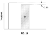
- FIG. 24 shows that total DNA comparison between female sperm cell and male sperm cell.
- FIG. 25 shows staining of DNA in cells to determine the intensity of emitted light which correlates with the amount of DNA in a cells, wherein 3.8% more light emitted correlates to 3.8% more DNA in female sperm cells.
- FIG. 26 shows the excitation wavelength and the emission wavelength for cells stained with Hoescht 33342.
- FIG. 27 shows a multiple station setup to analyze cells with a vanguard laser.
- FIG. 28 shows beam splitting occurring for multiple stations.
- FIG. 29 shows that Stoke shift and optical filter creates peak at 450 nm wavelength—therefore setting our detection wavelength.
- FIG. 30 A shows the knife blade shape, which requires tight focusing of cell stream.
- FIG. 30 B shows that a kill pulse is triggered based on a timer is when a cell is detected
- the present invention relates to a microfluidic chip with an interrogation apparatus which detects and interrogates objects in a sample fluid mixture, and a focused energy apparatus which performs an action on the objects or a region around the objects.
- the interrogation apparatus interrogates the objects to identify the objects, and to determine whether the objects should be targeted by the focused energy apparatus.
- the targeted objects are unwanted targeted objects.
- the focused energy apparatus is a discrimination apparatus which discriminates between targeted and non-targeted objects by damaging, killing, altering, disabling, or destroying the targeted objects.
- the present invention is conducted in a flowing, continuous fluid stream within the microfluidic network, where objects are subject to hydrodynamic focusing, positioning and orientation, and non-targeted objects are allowed to flow through the microfluidic chip undisturbed, and targeted objects may be acted upon, including photodamaged, killed, altered, disabled, or destroyed, by a focused energy apparatus.
- the various embodiments of the present invention provide for the selection of objects in a fluid mixture, such as, for example: selecting viable or motile sperm from non-viable or non-motile sperm; selecting sperm by gender, and other sex selection variations; selecting stems cells from cells in a population; selecting one or more labeled cells from un-labeled cells distinguishing desirable/undesirable traits; selecting cells for desirable characteristics; selecting genes in nuclear DNA in cells, according to a specified characteristic; selecting cells based on surface markers; selecting cells based on membrane integrity (viability), potential or predicted reproductive status (fertility), ability to survive freezing, etc.; selecting cells from contaminants or debris; selecting healthy cells from damaged cells (i.e., cancerous cells) (as in bone marrow extractions); red blood cells from white blood cells and platelets in a plasma mixture; and selecting any cells from any other cellular objects, into corresponding fractions; selecting damaged cells, or contaminants or debris, or any other biological materials that are desired to discriminated.
- the objects may be cells or
- a heterogeneous population of objects may be measured, with each object being examined for different quantities or regimes in similar quantities (e.g., multiplexed measurements), or the objects may be examined and distinguished based on a label (e.g., fluorescent), image (due to size, shape, different absorption, scattering, fluorescence, luminescence characteristics, fluorescence or luminescence emission profiles, fluorescent or luminescent decay lifetime), and/or particle position etc.
- a label e.g., fluorescent
- image due to size, shape, different absorption, scattering, fluorescence, luminescence characteristics, fluorescence or luminescence emission profiles, fluorescent or luminescent decay lifetime
- the subject matter of the present disclosure is also suitable for other medical applications as well.
- the various laminar flows discussed below may be utilized as part of a kidney dialysis process, in which whole blood is cleansed of waste products and returned to the patient.
- the various embodiments of the present disclosure may have further applicability to other biological or medical areas, such as for selection of cells, viruses, bacteria, cellular organelles or subparts, globular structures, colloidal suspensions, lipids and lipid globules, gels, immiscible particles, blastomeres, aggregations of cells, microorganisms, and other biological materials.
- the object selection in accordance with the present disclosure may include cell “washing”, in which contaminants (such as bacteria) are removed from cellular suspensions, which may be particularly useful in medical and food industry applications.
- the present invention has applicability to select non-motile cellular objects from motile cellular objects.
- the subject matter of the present disclosure may also be utilized to transfer a species from one solution to another solution where separation by filtering or centrifugation is not practical or desirable.
- additional applications include selecting colloids of a given size from colloids of other sizes (for research or commercial applications), and washing particles such as cells, egg cells, etc. (effectively replacing the medium in which they are contained and removing contaminants), or washing particles such as nanotubes from a solution of salts and surfactants with a different salt concentration or without surfactants, for example.
- the action of selecting species may rely on a number of physical properties of the objects or objects including self-motility, self-diffusivity, free-fall velocity, or action under an external force, such as an actuator, an electromagnetic field or a holographic optical trap.
- the properties which may be selected include, for example, cell motility, cell viability, object size, object mass, object density, the tendency of objects to attract or repel one another or other objects in the flow, object charge, object surface chemistry, and the tendency of certain other objects (i.e., molecules) to adhere to the object.
- the apparatus, methods and systems of the present invention may be extended to other types of particulate, biological or cellular matter, which are capable of being interrogated by fluorescence techniques within a fluid flow, or which are capable of being manipulated between different fluid flows into one or more outputs.
- a concentration of objects 160 is determined using a cell counting device, such as a Nucleocounter.
- 200 ⁇ 106/ml/1500 ⁇ 106/ml 0.133 ml neat semen, which is added to (in order) 0.012 ml Hoechst 33342 (5 mg/ml stock solution), and 0.855 staining TALP (pH 7.4), to equal 1 ml total staining volume at 200 ⁇ 106/ml.
- staining TALP is prepared by filling a container (i.e., beaker) with Milli-Q water to 2/3 of the total desired volume. A stir bar and stir plate are used to mix the solution as chemicals are added.
- the chemicals, which are added in the order listed (up to the Gentamicin, which is added later), include:
- the pH is adjusted to 7.4 using NaOH.
- Additional Milli-Q water is used to bring the solution to a final volume in a container (i.e., volumetric flask).
- a sterile filter i.e., 0.22 sterile filter
- An antibiotic i.e., Gentamicin solution
- the volume of staining TALP is stored at 5° C., and can be used for 7-10 days.
- the stained samples 120 are placed in containers (i.e., tubes) into a water bath set at 34-35° C., and incubated for a predetermined time (i.e., 45 minutes). In one embodiment, after incubation, the stained samples are removed from the water bath, and an equal volume of 4.0% egg-yolk TALP with red food dye that has been warmed in the water bath set to 34-35° C., is added.
- the staining TALP as noted above is prepared, and a desired volume of final solution is determined.
- the volume of staining TALP and egg yolk required to prepare a 4% egg yolk solution is calculated as follows:
- the desired volume: (250 ml) ⁇ 0.04 10 ml egg yolk needed for 4% solution.
- 240 ml of staining TALP is added to a graduated container (i.e., cylinder), and 10 ml of egg yolk is added.
- FD&C #40 food dye is added to the container (i.e., cylinder), to obtain: 0.261 ml/100 ml of solution.
- 0.261 ml ⁇ 250 ml/100 0.653 ml of red food dye.
- the container i.e., cylinder
- the container i.e., cylinder
- the container i.e., cylinder
- the container is covered with parafilm and carefully inverted until the volume is thoroughly mixed.
- the volume container is then allowed to sit overnight and cooled in a cool room.
- the volume container is then carefully decanted into a sterile container, leaving any sediment at the bottom of the volume container.
- the volume is then filter/sterilized through a 0.22 .tm bottle top filter, and an appropriate amount of antibiotic solution is added (i.e., 0.250 ml Gentamicin/100 ml of egg yolk TALP).
- the stained samples 120 are filtered by pouring the samples 120 into a 20-micron filter (i.e., CellTrics filter), that drains into another sterile 5 ml culture container. After a predetermined time of staining (i.e., 45 minutes), equal volume of 4% egg yolk TALP is added.
- the stained sample 120 i.e., cells
- a filter i.e., Partec filter, with 50 micron mesh
- a new sample aliquot 120 can be prepared and used every hour is desired.
- the various embodiments of the microfluidic chip utilize one or more flow channels, having a plurality of substantially laminar flows, allowing one or more objects to be interrogated for identification by an interrogation apparatus, and to be acted upon by a focused energy apparatus, with the objects exiting the microfluidic chip into one or more outputs.
- the objects not targeted by the focused energy apparatus are undisturbed, and the focused energy apparatus photodamages, alters, disables, kills or destroys targeted objects.
- the various embodiments of the present invention thereby provide selection of objects on a continuous basis, such as, within a continuous, closed system without the potential damage and contamination of prior art methods, particularly as provided in sperm separation.
- the continuous process of the present invention also provides significant time savings in selecting and discriminating objects.
- FIG. 1 A is an illustrative embodiment of a microfluidic chip 100 .
- the microfluidic chip 100 is manufactured of a suitable material such as glass, or a thermoplastic (e.g., low auto-fluorescing polymer etc.), or combination of materials, through an embossing process, soft photolithography, or injection molding process, as well known to one of ordinary skill in the art, and is of suitable size.
- a suitable material such as glass, or a thermoplastic (e.g., low auto-fluorescing polymer etc.), or combination of materials, through an embossing process, soft photolithography, or injection molding process, as well known to one of ordinary skill in the art, and is of suitable size.
- Each layer may be any suitable thickness, for example, the thickness may be within a range of approximately 300-400 ⁇ m, and more preferably the thickness may be approximately 400 ⁇ m.
- the microfluidic chip 100 includes one or more structural layers in which are disposed micro-channels which serve as sample input channel(s), sheath or buffer fluid channel(s), output channel(s), etc.
- the micro-channels are of suitable size to accommodate laminar flow streams containing objects, and may be disposed in any of the layers of the chip 100 in the appropriate length, as long as the object of the present invention is realized.
- the dimensions of the microfluidic channels range from 50 microns to 500 microns, with 100-300 microns being preferably used to avoid clogging.
- the desired flow rate through the microfluidic chip 100 may be controlled by a predetermined introduction flow rate into the chip 100 , maintaining the appropriate micro-channel dimensions within the chip 100 , by pumping mechanisms which pump external fluids into the chip 100 , and by providing narrowing or tapering of the micro-channels at various locations, and/or by providing obstacles, ramps, or dividers within the micro-channels (further discussed below).
- a plurality of inputs is provided into the microfluidic chip 100 , which inputs provide access to the micro-channels/channels.
- a sample input 106 is used for introducing a sample of particles or objects (i.e., cells) 160 in a sample fluid mixture 120 into a main fluid channel 164 of the microfluidic chip 100 from at least one reservoir source (see FIG. 19 ).
- the microfluidic chip 100 also includes at least one sheath or buffer input for the introduction of sheath or buffer fluids.
- there are two sheath or buffer inputs in the microfluidic chip 100 which include a sheath or buffer input 107 and sheath or buffer input 108 , both disposed proximate to the sample input 106 , and which both introduce sheath or buffer fluids 163 into the microfluidic chip 100 (see FIGS. 1 A- 3 B ).
- sheath or buffer inputs 107 , 108 , and 172 there are three sheath or buffer inputs 107 , 108 , and 172 (see FIGS. 1 A and 3 B ) which introduce sheath or buffer fluids into the channel 164 of the microfluidic chip 100 .
- the location of the sheath or buffer inputs 107 , 108 , 172 may vary, and they may access channels in the chip 100 which are in the same or different structural layers.
- the sheath or buffer fluids 163 are introduced into inputs 107 , 108 , 172 from a common reservoir (see FIGS. 20 - 21 ), or in another embodiment, from separate reservoirs (see FIG. 19 ).
- the sheath or buffer fluids are well known in the art of microfluidics, and in one embodiment, may contain nutrients well known in the art to maintain the viability of the objects 160 (i.e., sperm cells) in the fluid mixture.
- Commercially available Tris as sold by Chata Biosystems, is one example, and the sheath or buffer fluid 163 may be formulated to include the following: Water—0.9712 L; Tris—23.88 gg; citric acid monohydrate—11.63 g; D-fructorse—8.55 g.
- the pH is adjusted to 6.80 ⁇ 0.05 with hydrochloric acid, and osmolarity is adjusted, if necessary, to 270-276 mOsm with fructose high purity.
- the mixture is filtered using a 0.22 micron filter.
- the microfluidic chip 100 may have one or more structural layers in which the micro-channels are disposed.
- the channels may be disposed in one or more layers or in-between layers.
- the following embodiments describe a bonding process, but one of ordinary skill in the art would know how to achieve the various features by using an injection molding process. For example, in injection molding, instead of forming two layers, two molds could be made and joined together, such that an injection is made into the cavity in order to obtain the chip of the present invention.
- one structural layer 101 is included in the microfluidic chip, with a top, “blank” plastic layer 104 disposed thereon.
- the top, “blank” layer 104 bonds with the functional layer 101 to form an enclosed microfluidic network, and may have multiple holes to provide access to the lower layer(s) of the chip 100 .
- the top “blank” layer 104 may have holes corresponding to inputs 106 , 107 , 108 , 172 , etc., or provide holes 145 for pins to secure the layers 101 , 102 , 104 etc., of the chip 100 together.
- the top layer 104 of the microfluidic chip 100 includes a plurality of apertures configured to align with the fittings on a microfluidic chip holder 200 (further described below).
- two functional, structural plastic layers 101 - 102 are included in the microfluidic chip 100 , with no top, “blank” layer.
- the functional side of the top layer 102 is disposed on the underside of the layer 102 , so that when the layers are put together, the channels 114 , 115 , 116 , 117 are formed (see FIG. 1 B (b).
- FIG. 1 C (a) three functional, structural layers 101 , 102 , 103 are used in the microfluidic chip 100 .
- layers 102 , 103 include functional sides on the undersides of the layers 102 , 103 , with layers 101 and 102 forming channels 116 , 117 when put together.
- Layer 103 has channels 114 , 115 disposed on the underside of the layer 103 (see FIG. 1 C (b)).
- layer 102 includes 114 , 115 , and layers 101 and 103 each include one of channels 117 , 116 , respectively.
- a sample fluid mixture 120 including objects 160 is introduced into sample input 106 , and the fluid mixture 120 flows through main channel 164 toward action chamber 129 (see FIGS. 1 A- 2 ).
- the sheath or buffer fluids 163 are introduced into sheath or buffer inputs 107 , 108 (see FIGS. 1 A- 2 ) in most embodiments, and into sheath or buffer inputs 107 , 108 , and 172 in another embodiment (see FIG. 1 A ).
- the sheath or buffer fluids 163 flow through channels 114 , 115 and 116 , 117 , into the main channel 164 , and towards the action chamber 129 before flowing out through at least output channels 140 and 142 , in laminar flow.
- the fluid mixture 120 from main channel 164 joins with the sheath or buffer fluids 163 from channels 114 , 115 at intersection 161 of the microfluidic chip 100 .
- buffer fluids 163 from channels 116 , 117 join the combined fluid mixture 120 and sheath or buffer fluids 163 from first intersection 161 , downstream at second intersection 162 (see FIGS. 1 A- 2 ).
- sheath or buffer fluids 163 are inputted via input 172 into main fluid channel 164 , downstream from the second intersection 162 (see FIGS. 1 A and 3 B ).
- channels 114 , 115 are substantially the same dimensions as channels 116 , 117 , as long as the desired flow rate(s) is achieved to accomplish the object of the present invention, but one of ordinary skill in the art would know that the dimensions may be different as long as they accomplish the desired results (further discussion below).
- channels 114 - 117 and 140 - 142 may have substantially the same dimensions, however, one of ordinary skill in the art would know that the size of any or all of the channels in the microfluidic chip 100 may vary in dimension (for example, between 50 and 500 microns), as long as the desired flow rate(s) is achieved to accomplish the object of the present invention.
- the channels 114 , 115 or 116 , 117 are disposed in the same structural layer or plane of the microfluidic chip 100 , than the layer or plane in which the channel 164 is disposed (see FIG. 1 A , for example), or may be disposed in a different structural layer or plane (see FIG. 1 B , for example).
- the input channel 164 and the sheath channels 114 , 115 or 116 , 117 may be disposed in-between structural layers or planes of the chip 100 .
- the channels 114 - 117 , 164 , and 140 - 142 , etc. can be disposed in any layer or between any two layers.
- channels 114 - 117 , 164 , and 140 - 142 , etc. are described in exemplary embodiments as shown in the Figures, one of ordinary skill in the art would know that the particular arrangement or layout of the channels on the chip 100 may be in any desired arrangement as long as they achieve the described features of the present invention.
- the channels 116 , 117 are cut through layer 101 (see FIGS. 1 A and 2 ), and join the fluid mixture 120 in channel 164 in the same plane, via holes cut through the layers.
- channels 116 , 117 substantially parallel input channel 164 , and each join intersection 161 at an angle from channel 164 (see FIGS. 2 - 3 ).
- the sheath or buffer fluids from channels 116 , 117 compress the fluid mixture 120 flow horizontally from the sides, or laterally, such that the objects 160 in the fluid mixture 120 are flattened and/or oriented in a selected or desired direction, while still maintaining laminar flow in channel 164 (i.e., the first in two steps of hydrodynamic focusing, as described further below).
- channels 114 , 115 join the fluid mixture 120 in channel 164 at intersection 162 , with each channel 114 , 115 at an angle from channel 164 (see FIG. 1 A ).
- the sheath or buffer fluids from channels 114 , 115 compress the fluid mixture 120 flow with respect to channel 164 (see FIG. 14 ), such that the objects 160 in the fluid mixture 120 are further flattened and/or oriented in the selected or desired direction, while still maintaining laminar flow in channel 164 (i.e., the second in two steps of hydrodynamic focusing, as described further below).
- a third sheath or buffer fluid input 172 is disposed downstream from intersection 162 (see FIG. 3 B ), which allows a third hydrodynamic focusing step to take place, where the sample fluid mixture 120 is compressed from above the channel 164 by the sheath or buffer fluids 163 introduced therein.
- the channels 114 , 115 join the fluid mixture 120 in channel 164 at intersection 162 from an angle from above (see FIG. 3 A )—and may be above and below (see FIG. 12 A )—channel 164 , to compress the fluid mixture 120 from a vertical direction to further flatten and/or orient the objects 160 in the channel 164 (i.e., the second hydrodynamic focusing step).
- microfluidic chip 100 sheath or buffer inputs, sample input, and sample input channel and sheath or buffer channels, as well as the hydrodynamic focusing steps, may be different as long as they achieve the desired features of the present invention.
- channels 114 , 115 and 116 , 117 are depicted as partially coaxial to one another with a center point defined by the sample input 106 .
- channels 114 , 115 and 116 , 117 are disposed in a substantially parallel arrangement, with the channels 114 , 115 and 116 , 117 being equidistant to main channel 164 .
- the depicted configuration may be different as long as it achieves the desired features of the present invention.
- holes and pins/posts 145 are disposed at various convenient positions in the layers 101 , 102 , 103 , 104 etc., to fix and align the multiple layers during chip 100 fabrication.
- a gasket 105 of any desired shape, or O-rings may be provided to maintain a tight seal between the microfluidic chip 100 and the microfluidic chip holder 200 (see FIGS. 1 D and 21 - 22 , for example).
- a gasket 105 it may be a single sheet or a plurality of objects, in any configuration, or material (i.e., rubber, silicone, etc.) as desired.
- a first gasket 105 is disposed at one end of the microfluidic chip 100 and interfaces, or is bonded with layer 104 .
- a plurality of holes 144 are provided in the first gasket 105 and are configured to align with the sample input 106 , sheath/buffer input 107 , and sheath/buffer input 108 .
- a second gasket 143 may be disposed at another end of the microfluidic chip 100 opposite to the first gasket 105 (see FIG. 1 D , for example), and interfaces or is bonded with (using epoxy) the top structural layer 104 (see FIGS. 1 D and 21 - 22 ).
- O-rings are used instead of gaskets, to assist in sealing, as well as stabilizing the microfluidic chip 100 in the chip holder 200 .
- one or more gaskets or O-rings may be applied to the outer layers of the chip 100 in order to protect the chip 100 in a chip holder 200 , during operation thereof.
- the channels 114 - 117 , and 140 - 142 , of the microfluidic chip 100 may not just vary in dimension, but may have tapered shapes at entry points to other channels in the chip 100 in order to control the flow of fluid through the channels.
- main channel 164 may taper at the entry point into intersection 161 (see FIG. 4 A , taper 166 A), or at the entry point into intersection 162 (see FIG.
- FIGS. 3 A- 3 B, 4 A- 4 B , and tapers 166 A to control and speed up the flow of sample 120 into the intersection 161 , and allow the sheath or buffer fluids 163 from channels 116 , 117 or 114 , 115 , respectively, to compress the sample fluid mixture 120 in a first direction (i.e., horizontally or laterally) on at least two sides, if not all sides (depending on where the fluid channel 164 enters the intersection 161 ), and in a second direction (i.e., vertically) (see FIGS. 3 A- 3 B, 4 A- 4 B , and tapers 166 A).
- a first direction i.e., horizontally or laterally
- a second direction i.e., vertically
- ramps may be disposed in channel 164 or channels 114 - 117 to achieve the effect of controlling and speeding up the sample flow through the channels.
- the ramps may be in addition or instead of tapers.
- a ramp 166 B may be disposed in channel 164 prior to the sample flow approaching intersections 161 and 162 , respectively, or prior to entering action chamber 129 (see FIGS. 4 A and 4 B ).
- the sample fluid mixture 120 becomes a relatively smaller, narrower stream, bounded or surrounded by sheath or buffer fluids 163 , while maintaining laminar flow in channel 164 .
- the main channel 164 , or the buffer channels 114 - 117 may be of any physical arrangement, such as a rectangular or circular-shaped channel, with tapers, ramps, or other internal features, as long as the object of the present invention is obtained.
- a plurality of output channels stemming from main channel 164 is provided for removal of fluid flowed through the microfluidic chip 100 , including any targeted or non-targeted objects 160 and/or sheath or buffer fluids 163 .
- the left side output channel 140 ends at a first output 111
- the center output channel 141 ends at a second output 112
- the right side output channel 142 ends at a third output 113 .
- output channels 140 - 142 depart from channel 164 within chamber 129 to outputs 111 - 113 .
- the cross-section and the length of the output channels 140 - 142 should be maintained at a predetermined volume ratio (i.e., 2:1:2, or 1:2:1 etc.) to obtain the desired hydraulic resistance of the output channels 140 - 142 .
- the output channels 140 - 142 increase in dimension from the channel 164 , leaving the chamber 129 , such that the output ratio for the objects 160 , is increased through the relevant channel 141 .
- a plurality of notches or recesses 146 may be disposed at a bottom edge of the microfluidic chip 100 to separate the outputs (i.e., outputs 111 - 113 ) and for the attachment of containers, and external tubing (for recycling the sheath or buffer fluids 163 —see FIGS. 19 - 21 ) etc.
- the first output 111 , the second output 112 and the third output 113 are reached via output channels 140 - 142 which originate from action chamber 129 (see FIG. 2 ).
- a container 188 collects the objects 160 from the second output 112 , although other containers may collect the output from first output 111 and third output 113 (see FIGS. 6 A- 6 D ).
- portions of the first, second, and third outputs 111 - 113 may be characterized electronically, to detect concentrations of objects 160 , pH measuring, cell 160 counts, electrolyte concentration, etc.
- the targeted objects 160 are acted upon by the focused energy apparatus 157 , and those objects 160 , as well as non-targeted objects 160 , may be collected as product 165 from the second output 112 .
- the product 165 of targeted and non-targeted objects 160 may continue to be processed for storage, for further separation, or for processing, such as cryopreservation (discussed further below).
- the microfluidic chip 100 is provided in a sterile state, and may be primed with one or more solutions (i.e., sheath or buffer fluids 163 ), or purged of any fluids or materials by either draining the microfluidic chip 100 or by flowing sheath or buffer fluids 153 or other solutions through the microfluidic chip 100 , according to known methods.
- solutions i.e., sheath or buffer fluids 163
- channel 164 tapers into the chamber 129 (see FIG. 4 B ), which speeds up the flow of the fluid mixture through the chamber 129 .
- the channel 164 need not taper and could be of any dimension and size as long as the present invention performs according to the desired requirements.
- an interrogation apparatus 147 is used to interrogate and identify the objects 160 in the fluid mixture in channel 164 passing through the chamber 129 . Further, in one embodiment, the focused energy device 157 also acts upon the objects 160 passing through the chamber 129 .
- the chamber 129 includes a relatively small diameter opening or window 150 (see FIG. 5 ) cut through the microfluidic chip 100 and layers 101 - 102 , through which the objects 160 can be visualized as they pass through channel 164 .
- a relatively larger diameter and shallow opening is cut into layer 104 as a top window, and into layer 101 as a bottom window.
- the top window is configured to receive a first transparent covering 133
- the bottom window 152 is configured to receive a second transparent covering 132 .
- the coverings 133 , 132 may be made of any material with the desired transmission requirements, such as plastic, glass, or may even be a lens.
- a contiguous plastic sheet can be used instead of a window with coverings. Note that although the relative diameters of the coverings 132 , 133 and opening 150 are shown in FIG. 5 , these may vary according to design or manufacturing considerations.
- the above-mentioned first and second coverings 133 , 132 are configured to enclose the chamber 129 .
- the windows and coverings 133 , 132 (see FIG. 5 ), allow the objects 160 flowing in the fluid mixture 120 in channel 164 through the chamber 129 , to be viewed through opening 150 , and acted upon by a suitable light source 147 and a focused energy apparatus 167 (discussed later).
- windows and/or openings are not required due to the structure of the chip layers (i.e., glass), and/or their configuration, or the focused energy device 157 and light source 147 wavelengths and power levels are such that no damage to the chip 100 will occur.
- the interrogation apparatus of the present invention includes a light source 147 which is configured to emit a high intensity beam 148 with any wavelength that matches excitable objects in the fluid mixture 120 (see FIG. 5 ).
- a laser 147 is preferred, any suitable other light sources 147 may be used, such as a light emitting diode (LED), or arc lamp, etc. to emit a beam which excites the objects.
- LED light emitting diode
- arc lamp etc.
- a 532 nm green laser 147 is utilized.
- the laser 147 (see FIG. 5 ) emits a laser beam 148 through the covering 133 at an uppermost portion of the chip 100 , through opening 150 , to illuminate the objects 160 flowing through channel 164 in chamber 129 of the chip 100 , and then through covering 132 in layer 101 of the chip 100 ,
- the light beam 148 can be delivered to the objects 160 by an optical fiber that is embedded in the microfluidic chip 100 at opening 150 .
- the high intensity beam 148 interacts with the objects 160 (see detailed explanation below), and passes through the first coverings 133 , to exit from the covering 132 at the bottom window, such that the emitted light 151 , which is induced by the beam 148 , is received by an objective lens 153 or other collection optics.
- the objective lens 153 or other collection optics may be disposed in any suitable position with respect to the microfluidic chip 100 —for example, parallel to the main channel with the optical axis perpendicular to the sample fluid flow 120 . Because the chamber 129 is sealed by the first and second coverings 133 , 132 , the high intensity beam 148 does not impinge on the microfluidic chip 100 and damage the layers 101 , 104 (see FIG. 1 A ). Thus, the first and second coverings 133 , 132 help prevent damage to the microfluidic chip 100 from the high intensity beam 148 and photonic noise induced from the microfluidic chip 100 material (i.e., plastic).
- the light beam 148 passes through the chip 100 and the emitted light 151 received by the objective lens 153 or other collection optics, is detected by detector 154 , and is converted into an electronic signal by an optical sensor 154 , such as a photomultiplier tube (PMT) or photodiode, etc.
- the electronic signal can be digitized or processed by an analog-todigital converter (ADC) 155 and sent to a digital signal processor (DSP) based controller 156 or computer.
- DSP digital signal processor
- the electronic controller 156 can be any electronic processer with adequate processing power, such as a DSP, a Micro Controller Unit (MCU), a Field Programmable Gate Array (FPGA), or even a Central Processing Unit (CPU).
- the DSP based controller 156 monitors the electronic signal, and based upon predetermined criteria, the focused energy apparatus 157 may be employed when a targeted object 160 is detected.
- the interrogation apparatus simply interrogates the objects 160 in the sample fluid flow 120 for identity, and it is not connected to the employment of the focused energy apparatus 157 (see FIG. 6 C ).
- a focused energy apparatus 157 is used to provide focused energy pulses to the objects 160 .
- the focused energy apparatus 157 may be a thermal, electrical, optical, or electromagnetic device 157 , which would have a desired wavelength, and would deliver high peak power with a very high repetition rate (or pulse frequency), to the target objects 160 .
- the focused energy apparatus 157 is triggered a predetermined time (i.e., milliseconds) after activation by the controller 156 (the timing being set based upon the traveling speed of objects 160 through the channel 164 , and is discussed further below), and issues a pulse to the selected or targeted (i.e., unwanted) object 160 .
- a predetermined time i.e., milliseconds
- pulsed lasers 157 include mode-locked, Q-switch, as well as those lasers using both mode-locking and Q-switch techniques.
- a focused energy device 157 such as an Avia 355-5-100 (made by Coherent, Inc., Santa Clara, CA), or the Explorer XP lasers Q-switch laser from Spectra-Physics Inc., is capable of operating in a pulse-on-demand mode, and can deliver 15 ns energy pulses or less, at a rate of over 1000 pulses per second, to the target objects 160 .
- pulse energy levels of 0.5-8.0 ⁇ J are used, and in a preferable embodiment, a Q-switch laser 157 in pulse-on-demand mode is used to deliver an average pulse energy of 1.8 pJ with a range for individual pulses of 1.3 pJ to 2.3 ⁇ J.
- the pulse width ranges from 3 nanoseconds to 1 microsecond, and preferably, is in a range of 5-9 nanoseconds.
- any high power laser existing now, or later developed, with the appropriate high energy pulses and pulse frequency would be suitable for the present invention in order to achieve the desired target accuracy and/or effect.
- the need for a tight action region i.e., chamber 129 , or space between the chip 100 and container 188 ) in order to deliver the pulsed energy from the focused energy apparatus 157 to target objects 160 or a surrounding region thereof, is important to minimize the potential impact of delivering the energy outside of the targeted objects 160 or region, to otherwise unselected, or non-targeted objects 160 .
- a focused energy apparatus 157 such as the Explorer XP 355-1 Q-switch laser, is capable of delivering ⁇ 4% rms, providing high pulse-to-pulse stability when fired at regular uniform intervals.
- additional measures are employed to deliver uniform pulse energy 158 to impinge only the targeted objects 160 or cells, or the surrounding region thereof.
- Such measures include matching laser 157 performance parameters such as pulse length and peak power levels, to enable the system of the present invention to achieve a desired target accuracy (i.e., in one embodiment, photodamage or kill rate of 95% or higher hit rate on target objects 160 ).
- the focused energy apparatus 157 is utilized in an action region 129 , such as chamber 129 , prior to interrogation by the interrogation apparatus 157 (see FIG. 6 D ), and in another embodiment, the focused energy apparatus 157 is utilized in the action region (i.e., chamber 129 ) after interrogation by the interrogation apparatus 157 (see FIG. 6 A ). In yet another embodiment, the focused energy apparatus 157 acts upon the sample fluid with objects 160 after it leaves the chip 100 and enters a container 188 —either at the output 112 , or in disconnected droplet form 187 before it enters the container 188 (see FIGS. 6 B-C ).
- the focused energy apparatus 157 acts upon the objects 160 after they are interrogated by the interrogation apparatus 147 in the action region 129 (i.e., chamber 129 ), upon determination that the objects 160 are to be targeted, the focused energy apparatus 157 emits a focused energy beam 158 to act upon the objects 160 flowing through channel 164 (see FIGS. 5 and 6 A- 6 C , for example).
- the focused energy apparatus 157 acts upon the objects 160 after interrogation in action region 129 , and after the objects 160 flow through output channel 141 , but before the sample fluid 120 is collected by container 188 .
- the focused energy apparatus 157 is utilized as above, but is positioned to emit the beam between the chip 100 and the container 188 .
- the sample fluid 120 simply falls from output 112 through the air into the container 188 in droplet form 187 , and in another embodiment, there may be a transparent enclosure between the chip 100 and the container 188 .
- the focused energy apparatus 157 can be set to damage, alter, disable, kill or destroy the targeted or unwanted object 160 in the sample fluid 120 with a pulse, or to activate one of several mechanisms in the object 160 or cell, such that cell damage or death ensues.
- the targeted or selected objects 160 may be wanted objects 160 , in which case the focused energy apparatus 157 is not activated or triggered, or the targeted or selected objects 160 may be unwanted objects 160 , where the focused energy apparatus 167 is activated act upon the objects 160 , such as to damage, alter, disable, kill or destroy the selected, unwanted objects 160 .
- the focused energy apparatus 167 is activated act upon the objects 160 , such as to damage, alter, disable, kill or destroy the selected, unwanted objects 160 .
- the object 160 when the selected object 160 is damaged, altered, disabled, killed, or destroyed by the focused energy device 157 , the object 160 continues to flow through the main channel 164 to the center output channel 141 , and to second output 112 , and into container 188 , along with any non-targeted objects 160 .
- the sheath or buffer fluids 163 proceed in laminar flow through output channels 140 , 142 , to outputs 111 , 112 , respectively.
- the objects 160 in channel 164 may flow out from the chip 100 through output channel 141 and single output 112 .
- the present methods and apparatus are capable of producing a discriminated product 165 (see FIGS. 6 A- 6 D ) of objects 160 in container 188 , including a high viability of non-target or wanted objects 160 or cells, and a high percentage of photodamaged, altered, disabled, destroyed, or dead target objects 160 .
- beam shaping optics for both the interrogation beam 148 and the focused energy beam 158 (see FIGS. 16 - 17 ).
- beam spot refers to a cross-section of either beam 148 , or beam 158 .
- the focused energy apparatus 157 is disposed downstream from light source 147 , and on the same side as the light source 147 (see FIG. 17 ), but the focused energy apparatus 157 may also be disposed downstream and on an opposite side of light source 147 (see FIG. 16 , for example).
- a beam shaping optics for the interrogation beam 148 are disposed on one side of chip 100 .
- the interrogation beam 148 from light source 147 passes through the action region (i.e., chamber 129 ) and is received by objective lens 153 .
- the beam 148 is expanded by beam shaping optics 181 , which may include a plurality of lenses, which arrangement would be well known to one of ordinary skill in the art.
- the beam shaping optics 181 may include a pair of prisms and a pair of cylindrical lenses with appropriate focal lengths, or may include other lenses, with or without prisms, which would be available to one of ordinary skill in the art.
- the beam expansion enables the final spot size at the focal point in the interrogation region 129 .
- the circular beam 148 spot is expanded using a beam expander 180 .
- the beam expansion also reduces the influence on the downstream optics, limiting damage and extending lifetime. However, in one embodiment, no beam expander is utilized. Alternatively, if the source beam has too large of a diameter, optics could be used to reduce that diameter to a suitable size.
- the beam shaping optics 181 include two perpendicular cylindrical lenses to alter the beam shape 148 into an ellipse perpendicular to the direction of sample fluid 120 flow, and along the direction of sample fluid 120 flow, when focused at the center thereof.
- This elliptical beam 148 spot serves to excite the objects 160 passing through the channel 164 of the microfluidic chip 100 , and provides maximum uniform illumination at a center area of the beam 148 spot, to compensate for minor fluctuations in the flow of objects 160 through the channel 164 .
- the ellipse of the beam shape having a wider dimension perpendicular to the sample fluid 120 flow helps to reduce variation in the fluorescence signal coming from the objects 160 (i.e., sperm cells) that are not perfectly centered within the sample fluid 120 flow stream.
- the narrow dimension keeps the beam 148 at a high enough intensity to adequately excite the fluorescent dye for interrogation of the objects 160 (i.e., sperm cells). While an elliptical beam 148 spot is preferred, in other embodiments of the present invention, a different shaped beam may be utilized.
- the power of the interrogation beam can be adjusted as well to assist in the interrogation and to limit impact on the interrogated objects
- the focused energy beam 158 is also shaped by beam shaping optics 180 .
- the shape of the focused beam 158 spot of the focused energy device 157 influences the desired target accuracy and potential for impacting non-target objects 160 in the channel 164 , and can be varying beam shapes, as the application requires.
- the beam width along the direction of flow of the sample fluid 120 should be adjusted to be sufficiently narrow such that only the target object 160 is affected, and sufficient beam intensity concentration is achieved.
- the length of the beam 158 spot across the fluid channel 164 can be intentionally adjusted to compensate for any slight instability and variability in the focused flow of the sample fluid 120 . Desired beam shaping can easily be achieved by one skilled in the art.
- beam shaping optics 180 for the focused energy beam 158 is utilized to focus the beam 158 down to a much smaller size to increase a laser flux in the action region 129 .
- the beam 158 is expanded by beam expander optics 180 (see FIG. 16 ) which may include a plurality of lenses or prisms with appropriate focal lengths, which would be readily known to one of ordinary skill in the art.
- the beam 158 passes through a pair of anamorphic prisms, for example, to shape the beam 158 .
- the beam 158 is further focused and compressed in the horizontal and vertical directions by an optical object due to a Gaussian beam property.
- the optical object may be, for example, detector optics 153 such as a microscope objective or a focusing lens with a short focal length.
- the beam spot provides a combination of energy concentration for efficient action (i.e., killing, etc.) and sufficient width to compensate for minor fluctuations in a flow of the objects 160 through the microfluidic channel 164 .
- a pair of cylindrical lenses is used to expand the beam in the vertical dimension, before a spherical focusing lens or objective lens is used to focus the beam to an elliptical beam spot of a minor diameter of 2 .tm and a major diameter of 20 gm.
- a different shape and/or dimension(s) may be used for the beam 158 . Note that other major and minor diameters are attainable by one skilled in the art and can be applied to the same process.
- the focused energy device 157 is implemented from the opposite side from the interrogation beam 148 , as shown in FIG. 17 .
- the configuration shown is advantageous because it is easily implemented and efficiently uses the free space at a photo detector side of the system.
- dichroic mirrors are used to split off specific wavelengths, or to integrate specific wavelengths into the optical path.
- a mirror and dichroic mirror/beam splitter may be used, one of ordinary skill in the art would know that more than one mirror and/or dichroic mirror/beam splitter may be utilized in the present system.
- collection optics 153 including a microscope objective, collect the fluorescence emission from the objects 160 in the chip 100 , and a dichroic mirror passes the fluorescence emission from the collection optics 153 towards the optical signal detector 154 .
- the focused energy device 157 emits a beam 158 which passes through beam shaping optics 180 (as described above), and which is directed by a mirror and also reflected by dichroic mirror through collection optics 153 onto the chip 100 .
- the objective lens of the collection optics 153 focuses the focused energy beam 158 , which enters the back aperture of the objective lens, into a tight spot on the objects 160 just slightly downstream from the interrogation/excitation point in action region 129 .
- the focused energy beam 158 may be disposed below the output 112 of the chip 100 , or slightly upstream from the interrogation/excitation region 129 .
- a distance between the beam spot of the interrogation beam 148 and the beam spot of the focused energy beam 158 is adjustable.
- a dichroic mirror or any beam splitting device may split a small bit of light off to a camera 182 (see FIG. 5 ), allowing the user to visually examine alignment.
- the camera 182 provides a visual image of the microfluidic flow environment for general alignment purposes.
- the camera can be used to determine location and timing for firing of the focused energy device 157 .
- the focused energy beam 158 is implemented from the same side as the interrogation beam 148 (see FIG. 17 ).
- the focusing lens for the focused energy apparatus 157 is not shared with the detection side, so it is more flexible for beam shaping, and it eliminates the need for a microscope objective which is rated for high power at the action (i.e., photodamage, killing) wavelength, which can reduce the system cost.
- the focused energy device 157 emits a beam 158 from the same side as the interrogation apparatus 147 , and the beam 158 is shaped by beam shaping optics 180 (described above), to be directed and aligned by a mirror and dichroic mirror, to be focused onto the objects 160 in channel 164 of the chip 100 .
- beam focusing optics 181 are disposed between a dichroic mirror and the chip 100 , to focus the beam 158 .
- the beam 158 is focused into a tight spot on the objects 160 just slightly downstream from the interrogation/excitation point in action region 129 .
- the focused energy beam 158 may be disposed below the output 112 of the chip 100 , or slightly upstream from the interrogation/excitation region 129 (see FIGS. 6 A-D ).
- a distance between the beam spot of the interrogation beam 148 and the beam spot of the focused energy beam 158 is adjustable.
- the microfluidic chip 100 design of the present invention focuses, positions and orients the objects 160 , in order to optimize its analytical capability.
- the objects 160 i.e., cells
- the objects 160 with non-spherical shapes are aligned into a restricted core volume in channel 164 and maintained in a similar and desired orientation when they pass through the interrogation/detection beam 148 .
- the orientation of objects 160 can be realized by positioning the sample core stream 120 offset with respect to the center of the central plane of the channel 164 cross-section, using hydrodynamic focusing.
- the following describes two-step hydrodynamic focusing that takes place during fluid flow in one embodiment of the microfluidic chip 100 (see FIGS. 1 B- 1 D ).
- the first hydrodynamic focusing step of the present invention is accomplished by inputting a fluid sample 120 containing objects 160 , including biological samples such as sperm cells 160 etc., through sample input 106 , and inputting sheath or buffer fluids 163 through sheath or buffer inputs 107 , 108 .
- the objects 160 are pre-stained with dye according to known methods (e.g., Hoechst dye), in order to allow fluorescence and imaging thereof.
- objects 160 in the sample fluid mixture 120 flow through main channel 164 , are surrounded and shaped by the fluid flow, and have random orientation and position (see FIGS. 3 A and 6 A ).
- the sample mixture 120 flowing in main channel 164 is surrounded and shaped by the sheath or buffer fluids 163 from channels 116 , 117 , and compressed in a first direction (i.e., at least horizontally, on at least both sides of the flow, if not all sides depending on where the main channel 164 enters the intersection 161 ), when the sheath or buffer fluids 163 meet with the sample mixture 120 .
- This compression is termed hydrodynamic focusing (three-dimensional (3-D)), and is used to align the objects 160 in the channel 164 into a restricted core volume that may approximate a single file formation.
- the hydrodynamic focusing takes advantage of significantly large sheath or buffer flow in channel 164 to accelerate the travelling velocity of the objects 160 through the planar microfluidic channel 164 .
- the sample core stream 120 may also be offset from the central plane by a ramp 166 B or taper 166 A structure in the channel 164 which is prior to the junction 161 of the channel 164 and the first-step sheath or buffer channels 116 , 117 .
- the objects 160 are speeded up and the spacing between the objects 160 in the microfluidic channel 164 also can be stretched.
- the velocity of the objects 160 is dependent upon the sample 120 flow rate and the ratio of the value to total sheath or buffer 163 flow rate. This function is useful to avoid clogging issues and object 160 clumping with highly concentrated object samples 120 .
- the resulting sample 120 core stream across the main channel 164 still shows overlapped objects 160 or cells along the channel 164 depth direction or vertical axis.
- the objects 160 are focused around the center of the channel 164 , and may be compressed into a thin strip across the depth of the channel 164 .
- the objects 160 i.e., sperm cells move toward the center of the channel 164 width.
- the present invention includes a second focusing step, where the sample mixture 120 containing objects 160 , is further compressed by sheath or buffer fluids 163 from a second direction (i.e., the vertical direction, from the top and the bottom) entering from channels 114 , 115 at intersection 162 (see FIG. 14 ).
- the intersection 162 leading into channel 164 B is the second focusing region. Note that although the entrances into intersection 162 from channels 114 , 115 are shown as rectangular, one of ordinary skill in the art would appreciate that any other suitable configuration (i.e., tapered, circular) may be used.
- the sheath or buffer fluids 163 in the channels 114 , 114 enter from the same plane (see FIGS. 3 A and 6 A ), or from different planes into the channel 164 (see FIG. 15 , where channels 114 , 115 are disposed above and below main channel 164 , entering channel 164 vertically), to align the objects 160 in the center of the channel 164 B by both width and depth (i.e., horizontally and vertically) as they flow along channel 164 B. Then, the resulting flow in the main channel 164 is subsequently compressed and repositioned by the second-step sheath flow via microfluidic channels 114 , 115 .
- the sample mixture 120 is again compressed by the vertical sheath or buffer fluids 163 entering at channels 114 , 115 , and the sample 120 stream is focused at the center of the channel 164 depth, as illustrated in FIG. 8 B , and the objects 160 flow along the center of the channel 164 in a restricted core volume that may approximate a single file formation in a particular orientation.
- a restricted core volume of objects 160 or cells is obtained and the position of the stream also can be adjusted to a desired location along the vertical axis (see FIG. 8 B ).
- the objects 160 introduced into sample input 106 undergo two-step hydrodynamic focusing, which allows the objects 160 to move through the channel 164 B in a restricted core volume that may approximate a single file formation, in a more uniform orientation (depending on the type of objects 160 ), which allows for easier interrogation of the objects 160 .
- three-step hydrodynamic focusing is performed on the objects 160 in the chip 100 .
- first two hydrodynamic focusing steps are accomplished by horizontally compressing the sample fluid stream 120 at intersections 161 and 162 , and then in a third step, the sample fluid stream 120 is vertically compressed in the channel 164 .
- Sheath or buffer channels 114 , 115 , and 116 , 117 enter the channel 164 from a horizontal direction, at an angle of 45 degrees or less for each channel.
- sample 120 flow enters into the first intersection 161 , and the sheath or buffer fluids 163 from channels 116 , 117 surround the sample 120 flow and immediately compress it into a thin sample 120 stream in channel 164 .
- the sample fluid channel 164 is tapered with an internal ramp prior to intersection 161 , where sheath or buffer fluid channel 116 , 117 enter the channel 164 (see FIG. 3 B ). Meanwhile, as the channel 164 is shallower (i.e., smaller in dimension) than the first sheath channels 116 , 117 , the sample 120 stream is lifted by the sheath or buffer fluid 163 from channels 116 , 117 , to flow to the top of the main channel 164 .
- the sheath or buffer fluids 163 are introduced from channels 114 , 115 into channel 164 —the channel 114 , 115 which are disposed close to the top of the main channel 164 (see FIG. 3 B ).
- sheath or buffer channels 114 , 115 join channel 164 horizontally, and may be of a smaller dimension from that of sheath or buffer channels 116 , 117 .
- the sheath or buffer fluids 163 further compress the sample 120 stream along the channel 164 width, to constrain the width of sample 120 stream. This sheath or buffer fluid 163 flow significantly improves the signal measurement sensitivity.
- the lack of vertical compressing at intersections 161 and 162 may result in multiple objects 160 or cells simultaneously entering the detection region 129 , thus, reducing the detection sensitivity or causing measurement errors, especially for a high throughput flow cytometry application.
- three-dimensional hydrodynamic focusing is an effective way to align the objects 160 in a restricted core volume that may approximate a single file formation in channel 164 . Further, the consistent positioning of the object 160 in the channel 164 results in minimum variability in velocity from object-to-object in the parabolic flow.
- FIG. 7 illustrates the profile of shear force on the cross-section of the microfluidic channel 164 .
- the shear force gradient shown in FIG. 7 has minimum shear force at the tapered tip and the larger region at the rear has the maximum shear value.
- the hydrodynamic shear force gradient is formed across the channel 164 cross-section.
- the large shear force close to the channel 164 wall helps to orient asymmetric objects 160 .
- the sample 120 flow shrinks into a very thin stream in both horizontal and vertical directions.
- the ratio of independently controlled sheath or buffer fluids 163 from channels 116 , 117 and 114 , 115 each determine the size of the resulting sample 120 stream in channel 164 .
- the objects 160 may spread a little along the channel 164 depth, but objects 160 still follow the sample 120 stream, which is very close to the top ceiling of the main channel 164 (note: with the chip described as horizontally disposed for ease of reference). Therefore, it is necessary to have a third sheath or buffer fluid 163 flow from channel 172 to further compress the sample 120 stream along the vertical direction, and confine the objects 160 well inside the thin, sample 120 stream.
- sheath or buffer fluid 163 flow is introduced perpendicularly to the pre-confined sample 120 stream from sheath or buffer channel 172 , it helps to position the sample 120 stream to a location along the cross-section of the channel 164 (i.e., achieves an end result as shown in FIG. 8 B ).
- the objects' 160 positions can be precisely controlled when they pass through the detection region 129 .
- the sheath or buffer fluid 163 is introduced by channel 172 from external sheath tubing (see FIG. 20 ) instead of by micro-channels running through the microfluidic chip 100 .
- an external flow controller is required to provide a constant and stable flow rate through the input channel 172 (see FIGS. 19 - 21 ).
- the design of the present invention allows the core sample stream 120 to orient flat-shaped objects, position the objects 160 in the channel 164 in a physical arrangement approaching uniformity, all of which improves the downstream precision action of the focused energy apparatus 157 .
- both sample fluid 120 and sheath or buffer fluids 163 are required to be precisely delivered so that a constant flow can be streamed through the microfluidic chip 100 .
- the ratio of the total sheath or buffer fluid 163 flow rate and the sample 120 flow rate can be adjusted between 100:1 and 1000:1.
- the ratio of 200-400:1 is used in the microfluidic chip 100 of the present invention.
- the overall fluid flow rate in the microfluidic chip 100 is about 2-4 ml/min.
- the introduced sheath or buffer fluid flows 163 have to be constant and pulse-free to ensure a stable traveling speed of the objects 160 during interrogation and signal detection, and between the detection/interrogation position and the position of the action of the focused energy apparatus 157 (see FIG. 6 A ). This facilitates an accurate signal reading and action on the target object 160 by the focused energy apparatus 157 .
- the overall flow rate variation is less than 1% of set flow rate, and the travelling speed of target objects 160 for potential action by the focused energy apparatus 157 varies less than 1% from the position where interrogation and detection of objects 160 takes place, to the position where the focused energy apparatus 157 acts on the objects 160 (see FIG. 6 A ).
- One of the challenging issues in the detection of flat-shaped objects 160 is to constrain the objects 160 in a uniform orientation when passing through the interrogation beam 148 .
- an approximately uniform positioning of objects 160 and a corresponding orientation of objects 160 in the channel 164 helps to increase the sensitivity of the system.
- the position of objects 160 along the channel 164 can be manipulated in a controlled way.
- an adjustment of 0-100 microns bias position of the objects 160 can be achieved.
- the high aspect ratio of the microfluidic channel 164 is taken advantage of to induce the shear force to turn the flat surface of the object 160 (i.e., sperm cell) facing the channel 164 wall.
- the sheath or buffer fluid 163 flow can be actively employed to compress and position the objects 160 in the channel 164 .
- an asymmetric geometry structure may be utilized to position the focused objects 160 in the channel 164 , by one of: a) placing an asymmetric ramp 166 B in the sample main channel 164 to lift the sample flow 120 (see explanation above regarding FIG. 4 A ); and b) placing an asymmetric ramp 166 B in the main channel 164 prior to the action chamber 129 to lift up the focused sample stream 120 (see explanation above regarding FIG. 4 B ).
- the above asymmetric features can be used individually or in an appropriate combination of two or more. However, one of ordinary skill in the art would know that these features are not necessary to the achievement of the position of the objects 160 in the channel 164 .
- ramps may be used in the channels 114 - 117 to lift the sample flow 120 , although they are not necessary.
- the placement of ramps in the channels is dependent upon the direction in which the objects 160 of the sample core stream 120 are required to be offset from the center to improve object 160 or cell orientation.
- the above passive method has less flexibility to vary the object 160 position in the main channel 164 .
- an asymmetric sheath flow 163 is introduced to adjust the positions of objects 160 or cells in the channel 164 .
- There are several methods of realizing asymmetric sheath or buffer fluid flow 163 two embodiments of which are described below.
- One embodiment is to introduce single sheath or buffer fluid flow 163 which forms a 90 degree angle with the main channel 164 wall, as shown in FIG. 3 A (in a two-step hydrodynamic focusing method) or FIG. 3 B (in a three-step hydrodynamic focusing method).
- the introduced sheath or buffer fluid flow 163 at the second-step hydrodynamic focusing intersection 162 further compresses the sample core stream 120 subsequent to the first-step hydrodynamic focusing at intersection 161 .
- this compressing of the sample core stream 120 occurs at the third-step hydrodynamic focusing intersection where channel 172 joins main channel 164 .
- the final hydrodynamic focusing step positions the objects 160 or cells to a desired location along the vertical axis. By controlling the ratio of the hydrodynamic focusing flow rates, a desired position of the objects 160 can be obtained to achieve the optimum orientation.
- two second-step sheath or buffer channels 114 , 115 merge in an angle to the main channel 164 wall, and parallel main channel 164 from above and below, as shown in FIGS. 12 A- 12 B .
- the angle of the second-step hydrodynamic focusing channels 114 , 115 and main channel 164 may vary and is dependent upon the fabrication methods. Preferably, a 90 degree angle is selected (see FIGS. 12 A- 12 B ). Different flow rates of sheath or buffer fluids 164 may flow via the two channels 114 , 115 , which are capable of repositioning the sample core stream 120 in the main channel 164 .
- the sperm cells 160 tend to turn their flat sides to the channel 164 wall in the vertical axis.
- the dimensions of the channels 114 , 115 are not necessarily identical (as shown in FIG. 12 A ), in order to obtain different hydraulic resistances.
- the same flow rate of the second-step sheath or buffer fluid flows 164 in the channels 114 , 115 will also generate bias fluid flow as well.
- both of the passive and active methods above can help to optimally position the objects 160 and improve their orientation in the channel 164 .
- pancake-shaped sperm cells 160 are taken as an example of the objects 160 . Because of their pancake-type or flattened teardrop shaped heads, the sperm cells 160 will re-orient themselves in a predetermined direction as they undergo the second, or third (depending on the embodiment) focusing step—i.e., with their flat surfaces perpendicular to the direction of light beam 148 (see FIG. 6 ). Thus, the sperm cells 160 develop a preference on their body orientation while passing through the hydrodynamic focusing process. Specifically, the sperm cells 160 tend to be more stable with their flat bodies perpendicular to the direction of the compression.
- the sperm cells 160 which start with random orientation, now achieve uniform orientation.
- the sperm cells 160 are not only disposed in a restricted core volume at the center of the channel 164 B, but they also achieve a uniform orientation with their flat surface normal to the direction of compression in the last hydrodynamic focusing step.
- the above methods improve the sperm cells' 160 orientation and the capability to differentiate the DNA content of X- and Y-sperm chromosomes (and thereby distinguish between X and Y sperm).
- the histograms of FIGS. 13 A and 13 B show the sperm cells 160 in the center of the channel 164 , and offset from the center of the channel 164 , respectively.
- the circles on the left and right of the histogram in FIG. 13 A shows the populations of mal-orientated sperm cells 160 .
- the left hump of the major population weakens the capability to differentiate X- and Y-sperm populations and contributes to the asymmetric distribution of X- and Y-sperm populations.
- the interrogation light source 147 is an excitation laser 147 (see FIG. 16 ), having 350 mW power, 355 nm wavelength, 12 ps pulse width.
- the objects 160 are detected in the action chamber 129 at opening 150 through covering 133 , using the light source 147 .
- Light source 147 emits a light beam 148 (which may be via an optical fiber) which is focused at the center of the channel 164 at opening 150 .
- the objects 160 are sperm cells 160 , which are oriented by the hydrodynamic focusing steps, such that the flat surfaces of the sperm cells 160 are facing toward the light beam 148 .
- all objects 160 or sperm cells 160 are moved into a restricted core volume that may approximate a single file formation, by the hydrodynamic focusing steps, as they pass under light beam 148 .
- the objects 160 pass under light source 147 and are acted upon by light beam 148 , the objects 160 emit the fluorescence which indicates the identity of the desired objects 160 .
- the light source 147 provides the fluorescence excitation energy for detection of objects 160 in the action region 129 .
- X chromosome cells fluoresce at a different intensity from Y chromosome cells (based on DNA content, as is well known in the art) (note: 355 nm is selected for the Hoescht 33342 dye used on the DNA).
- objects 160 which are cells carrying one trait may fluoresce in a different intensity or wavelength from cells carrying a different set of traits.
- the objects 160 can be viewed for shape, size, or any other distinguishing indicators.
- the illumination to the flat surface and the edge of the cells 160 is quite different with sperm cells 160 as compared to other cells.
- the fluorescence signal derived from the edge of the sperm cells 160 is significantly stronger than that from the flat surface, which increases the difficulty for the digital processor 156 to deal with the stronger signal from the edge, and the normal lower signal from the X- and Y-flat surface of the cells 160 .
- turning the flat surface of the sperm cell 160 to face the laser illumination i.e., light beam 148 ) helps to reduce the orientation variability and increase the capability of the system to differentiate X- or Y-sperm cells 160 .
- the emitted light beam 151 (in FIG. 5 ) is then collected by the objective lens 153 , and subsequently converted to an electronic signal by the optical sensor 154 .
- the electronic signal is then digitized by an analog-digital converter (ADC) 155 and sent to an electronic controller 156 for signal processing.
- ADC analog-digital converter
- the DSP-based controller 156 monitors the electronic signal, and when a particular signal is noted, a focused energy apparatus 157 may be employed to act upon a target object 160 (see FIGS. 6 A- 6 C ).
- the interrogation apparatus interrogates the objects 160 after they are acted upon by the focused energy device 157 (see FIG. 6 D ).
- interrogation of the sample 120 containing objects 160 is accomplished by other methods.
- portions of, or outputs from, the microfluidic chip 100 may be inspected optically or visually.
- methods for interrogation may include direct visual imaging, such as with a camera, and may utilize direct bright-light imaging or fluorescent imaging; or, more sophisticated techniques may be used such as spectroscopy, transmission spectroscopy, spectral imaging, or scattering such as dynamic light scattering or diffusive wave spectroscopy.
- the optical interrogation region 129 may be used in conjunction with additives, such as chemicals which bind to or affect objects 160 of the sample mixture 120 , or beads which are functionalized to bind and/or fluoresce in the presence of certain materials or diseases. These techniques may be used to measure cell concentrations, to detect disease, or to detect other parameters which characterize the objects 160 .
- polarized light back scattering methods may also be used.
- the objects 160 are interrogated as described above.
- the spectrum of those objects 160 which had positive results and fluoresced i.e., those objects 160 which reacted with a label) are identified for selection by the focused energy apparatus 157 .
- the objects 160 may be interrogated and identified based on the reaction or binding of the objects 160 with additives or sheath or buffer fluids 163 , or by using the natural fluorescence of the objects 160 , or the fluorescence of a substance associated with the object 160 , as an identity tag or background tag, or meet a selected size, dimension, or surface feature, etc.
- selection may be made, via computer 182 (which monitors the electronic signal and employs the focused energy apparatus 157 ) and/or operator, of which objects 160 to discard and which to collect.
- the focused energy apparatus 157 of the present invention may carry out a number of actions on the objects 160 in channel 164 , or between chip 100 and container 188 .
- the focused energy device 157 acts to photodamage or destroy the objects 160 in a number of ways.
- the focused energy apparatus 157 acts to kill objects 160 (i.e., cells).
- the target objects 160 may be unwanted cells 160
- cellular death may be caused by overheating of the intracellular environment, which may promote, but is not limited to, protein denaturation or reduction in enzyme activity.
- the action of the energy dosage 158 from the focused energy apparatus 157 is strong enough to cause rupture of the plasma membrane and leaking of the cellular contents out of the cell 160 and into the surrounding environment (i.e., sheath or buffer fluid 163 ).
- object 160 or cell death can be caused by the formation of radical oxygen species (ROS) due to adsorption of energy from the focused energy pulses 158 from the focused energy apparatus 157 , which will cause, among other things, DNA and protein damage.
- ROS radical oxygen species
- the focused energy apparatus 157 can temporarily or permanently disable target objects 160 , such as cells 160 , using focused energy pulses 158 from the focused energy apparatus 157 .
- exposing sperm cells 160 to focused energy pulses 158 such as those produced by a laser or LED 157 generates photo-activation within the cells 160 and results in temporary or permanent disablement of cellular mechanisms responsible for sperm 160 motility.
- the resulting sample 120 contains motile sperm 160 and immotile (target) sperm 160 , where the immotile sperm are unable to fertilize oocytes naturally.
- sperm cells 160 In addition to sperm cells 160 , one can use high powered focused energy sources 157 such as LEDs or lasers 157 to photobleach fluorescence in objects 160 , such as cells or colloids 160 , which express a predetermined level of fluorescence. For instance, in many self-assembly object formulations, a wide size range of objects 160 are formed that are difficult to separate from each other. To produce an enhanced sample 120 of objects 160 having a desired size, one can fluorescently label all objects 160 using methods known in the art, and one can use optical interrogation to determine object 160 size, and photobleach objects 160 possessing the predetermined level of fluorescence.
- a semen sample 120 may contain contaminants such as bacterial or viral cells, which are the target of photobleaching.
- Another example may include sperm cells 160 containing a given trait of the cell 160 or DNA and labeled with the fluorophore for quantitative and/or qualitative measurement.
- Sperm cells 160 containing the trait may be targeted by the focused energy apparatus 157 .
- sperm cells 160 which do not contain the trait may be targeted for photobleaching.
- Specific cells 160 in other cell mixtures such as blood are also candidates for photobleaching treatments to reduce viability.
- photobleached cells/objects 160 can be undetectable downstream and therefore, are not subject to subsequent processing steps (i.e., can by-pass subsequent processing steps).
- focused energy pulses 158 can be used to activate materials such as caged molecules or compounds within the objects 160 .
- the caged compounds represent, but are not limited to, fluorescent markers or cell responsive molecules.
- focused energy pulses 158 are used to cause photo-activation of the caged molecules or compounds which alters cell 160 signaling kinetics for ex-vivo therapies.
- focused energy pulses 158 can activate photo-polymerization events which disable cells or colloids 160 by altering internal properties of the object 160 .
- focused energy pulses 158 are used to activate heat shock proteins or induce mitochondrial biogenesis or activation within objects 160 or cells, including germ cells, to enhance cellular viability and functionality. Additional intracellular pathways may also be activated to repair damage done by either the interrogation/detection device 147 or a number of other factors that are too numerous to list (i.e., environmental, heat, chemical, etc.)
- one skilled in the art can generate photo-polymerization through focused energy pulses 158 to temporarily encapsulate or permanently contain target cells 160 , colloids, or other objects, using multi-armed PEG-acrylate/PEG-vinyl/etc., which promotes encapsulation of the target objects 160 or cells.
- Sperm cells 160 can be encapsulated to enhance the preservation of viability and fertility through commercial storage and delivery processes.
- focused energy pulses 158 are used to cause photo-polymerization events on the surface of targeted cells or objects 160 which increase the size or density of the encapsulating material in order to alter the size or density of the target object 160 or improve properties and performance of the encapsulating material.
- a photopolymerizable sequence in the hydrophobic portion of the vesicle may be used to permanently seal the desired molecule or object 160 by encapsulation therein.
- the focused energy apparatus 157 may be used to act on externally or alter the environment around the target objects 160 .
- focused energy pulses 158 are used to heat the local environment around target cells or objects 160 so that the thermal enhancement is sufficient to cause toxicity to target cells 160 .
- focused energy pulses 158 are used to promote rupturing of analyte containing delivery vehicles (such as vesicles) which are in close proximity to target cells 160 .
- the delivery vehicles carry molecules such as sodium fluoride (NaF) which causes temporary immobility of sperm cells 160 , or heparin which promotes capacitation of spermatozoa 160 .
- NaF sodium fluoride
- target sperm cells 160 or other objects respond to the local signals without activating similar responses in non-target cells 160 .
- the surrounding environment is modified with focused energy pulses 158 to vary the modulus of elasticity of the surface or release cell responsive chemicals from the surface of surrounding objects 160 or cells.
- heat production through absorption of light/EM waves 158 causes a temperature change which kills the objects 160 or cells.
- focused energy pulses 158 are used to form predetermined chemical bonds or break chemical bonds in the attachment material, thus, directing the differentiation of objects 160 , such as stem cells 160 , into differentiated cell lines.
- focused energy pulses 158 it is desirable to use focused energy pulses 158 to promote cellular uptake or adhesion onto target objects 160 .
- cellular uptake of antibodies, cellular probes, or DNA is enhanced through local heating.
- the object 160 to be delivered is attached to an object, that when targeted with a light source 147 , may cause a brief microbubble.
- an oligonucleotide may be conjugated to a gold nanoparticle.
- the gold is heated with a light source 147 at an optimized wavelength, a microbubble is briefly formed.
- the gold nanoparticles is broken apart and the pieces of the nanoparticle and the object attached to it are permeabilized through a cell membrane.
- the temperature increase of the target object 160 is not sufficient to cause the formation of a microbubble.
- the localized temperature increase is optimized to maintain cell viability and selectively promote the internalization of objects 160 into target viable cells.
- object 160 geometry or object 160 properties is altered, thus, enabling additional separation techniques, such as magnetic or electric fields to separate materials that are normally not susceptible to such forces.
- flow cytometric analysis and action systems that use an electromagnetic radiation source such as a focused energy apparatus 157 or laser, to act on selected objects 160 , typically desire to deliver a controlled energy level to individual objects 160 .
- such systems can kill, alter, damage, or destroy targeted objects 160 or cells using the focused energy apparatus 157 .
- such systems can, among other methods, activate targets in selected objects 160 or cells or in the fluid, media, or matrix surrounding selected objects 160 , as described above.
- radiation can be applied by methods of either targeted firing or continuous elimination, such that the desired objects 160 are unaffected, and the unwanted, altered, killed, destroyed or damaged objects 160 are discriminated from the sample 120 . Similar considerations as noted above, are given when selecting laser wavelength and laser power for targeted firing and continuous firing modes.
- the focused energy apparatus 157 is employed for targeted objects 160 .
- an object 160 in a sample 120 fluid mixture may pass through an interrogation/detection area in chamber 129 , for example, where specified characteristics of the object 160 are evaluated by one or more of the above methods.
- the focused energy apparatus 157 action area 129 is downstream from the optical interrogation area using light source 147 for interrogation.
- the focused energy apparatus 157 is utilized prior to interrogation further downstream.
- the focused energy apparatus 157 acts on the objects in action chamber 129 . The distance between the optical interrogation region and the action region may be adjusted to accommodate different timings.
- Objects 160 marked for action are hit with a triggered pulse of energy 158 from the focused energy apparatus 157 (see FIGS. 6 A- 6 C , for example).
- the object 160 or cell When the object 160 or cell is not targeted, it remains unaffected, and flows through the chamber 129 , via channel 164 to output channel 141 and container 188 , which collects target and non-target objects 160 as a discriminated product 165 .
- the laser pulse 158 has a short duration and can selectively target individual objects 160 or cells while exerting no intended impact on non-target objects 160 or cells which may be nearby, thus, avoiding “overspray” to non-target objects 160 or cells.
- Pulse energy is selected to impart the desired effect while avoiding undesired disturbances to the surrounding media, or for example, in flow systems, does not cause unintended cavitation or bubble formation.
- a variety of laser wavelengths can be used; however, the flux requirement may be different depending on the characteristics of the target object 160 , dye, and environment.
- Laser units 157 have limited power, especially those compact models that operate at high pulse frequency (>100 kHz typically), and it may be preferable to choose a laser wavelength that minimizes the required flux. For example, matching the laser 157 wavelength to the absorbance of dyes, other targets, or objects 160 (i.e., molecules) used in the action process greatly improves efficiency and effectiveness. Additionally, pulse energy 158 is selected to impart the desired effect while avoiding undesired disturbances to the surrounding media, or for example, in flow systems, not causing unintended cavitation or bubble formation.
- a 355 nm laser 157 was used to take advantage of the dye (i.e., Hoechst 33342 dye) used for the cell staining process.
- a 349 nm laser 157 may be used.
- pulse energy levels of 0.5-8.0 pJ are used.
- FIG. 26 shows the excitation wavelength and the emission wavelength for cells stained with Hoescht 33342.
- the focused energy pulse 158 is constantly employed and only interrupted for the passage of the non-target objects 160 (i.e., wanted objects 160 that are not to be damaged, destroyed, altered or killed), or debris or contaminants which do not require action thereon.
- the focused energy apparatus 157 such as a continuous wave (CW) or rapidly pulsed laser or LED, delivers a continuous stream of focused energy 158 to the objects 160 , and is used to act upon (i.e., including, photodamage, alter, disable, destroy, or kill) every object 160 passing through a particular location in the flow stream of the sample 120 fluid flow in an exemplary flow system.
- CW continuous wave
- the focused energy apparatus 157 delivers a continuous stream of focused energy 158 to the objects 160 , and is used to act upon (i.e., including, photodamage, alter, disable, destroy, or kill) every object 160 passing through a particular location in the flow stream of the sample 120 fluid flow in an exemplary flow system.
- the laser beam 158 is shut off, deflected, or otherwise interrupted for a short period of time, to allow the non-target objects 160 (in some cases, discarded items), to pass through unaffected.
- Methods for interrupting or diffusing the beam 158 include mechanical (shutters, choppers, galvanometer mirror), optical (acoustic optic deflector, acoustic optic modulator, spatial light modulator, digital micro-mirror device, polarization modification, liquid crystal display), electronic (pulse conditioning, dropping, or alteration of a Q-switch laser), or acoustic. Any other known or future suitable methods or techniques may be utilized to interrupt the focused energy beam 158 .
- the energy pulse 158 has a short duration and the focused energy apparatus 157 can selectively target only a single object 160 and not impact other objects 160 which are nearby in the sample 120 fluid flow (i.e., can limit “collateral damage”).
- the energy pulse 158 is selected to be sufficient to achieve the desired action on the object 160 (i.e., damage, alter, kill or destroy the object 160 ), per user requirements.
- the pulsed energy 158 from the focused energy apparatus 157 should fall within a range where it will not cause a disturbance to the sample 120 fluid due to cavitation, bubble formation, or method of energy absorbance.
- Other technologies for reducing unintended action, damage, and destruction to non-target objects 160 include those which absorb a significant portion of the pulse energy 158 , alter the direction of the beam 158 , or discharge excess energy by firing pulses 158 into the flow stream 120 .
- these can include mechanically moving a mirror or lens so as to defocus or deflect excess laser pulses 158 into an energy absorptive device, lenses altered electronically in order to change the laser's 157 propagation angle, and sophisticated triggering technologies which coordinate pulse energy data from the laser 157 with data about the object-to-object timing of objects 160 in the immediate flow stream.
- the timing between actions by the focused energy device 157 on the objects 160 is not uniform and follows a Poisson distribution where many short and extremely long intervals occur. Because a laser-based action system 157 includes inherent limiting factors, it is preferable to include a short “recharge time” between laser pulses 158 .
- the latency time (inherent in the focused energy apparatus 157 ), plus the “charge/recharge” time, is the minimum time that the focused energy apparatus 157 can react (deliver a pulse) and still provide the required energy level to the targeted object 160 .
- charge time should range from 0.1 Its to 1 second, and preferably should be from 0.1 ⁇ s to 4 ms.
- Pulse-to-pulse variability in energy levels affects the rate of producing the desired effect on target objects 160 or cells, and the potential for impacting non-target objects 160 or cells. When fired at non-uniform intervals, pulse-to-pulse stability should be high.
- a Q-switch laser 157 in pulse-on-demand mode was used to deliver average pulse energy of 1.8 ⁇ J with a range for individual pulses of 1.3 ⁇ J to 2.3 ⁇ J.
- the action region 129 may be located downstream from the optical interrogation region in the chamber 129 , or upstream thereof, and the distance between the optical interrogation region and the action region may be adjusted to accommodate different timings.
- the minimum timing between interrogation of the objects 160 or cells, and action on selected objects 160 or cells should be no less than 1 ⁇ s.
- the focused energy apparatus 157 operates successfully, for substantial periods, at action rates up to 5,600 objects per second, with accuracy rates which can be selected, and range for example, from 75-95%. In systems where spacing between objects 160 in the flow stream is controlled, the system 157 can operate at action rates up to the repetition rate of the laser 157 .
- the focused energy apparatus 157 is employed prior to interrogation of the object 160 .
- a histogram, or any graphical representation of the measured/calculated characteristics of the objects 160 after interrogation can be used in order to make the decision for action thereof on the population of objects 160 .
- the plot of the span i.e., transit time through the interrogation region of the chamber 129
- the plot of the span can reflect the relative size of the sample 120 core stream under different flow conditions, object 160 or cell distribution across the main channel 164 , and object 160 traveling velocity, as well as the variation of object 160 velocity within a particular chip 100 design.
- the high aspect ratio of the main channel 164 is important to object 160 or cell hydrodynamic focusing, migration, and orientation. In one embodiment, less than one for the high aspect ratio for the microfluidic channel 164 is used in the present invention. Preferably, 2/3 high aspect ratio is used for the main channel 164 .
- the value of the span itself roughly indicates the object 160 velocity. Large span value indicates that objects 160 pass the interrogation light beam 148 slowly. The tight size of the span indicates that the sample 120 core stream is closer to the channel 164 central plane and there is less object 160 velocity variation.
- the objects 160 are positioned close to the center of the cross-section of the channel 164 to reduce the velocity variation of the objects 160 .
- both orientation and velocity variation need to be taken into consideration.
- sperm cells 160 pushed offset from the central plane of the channel 164 along the vertical axis tend to obtain a better resolution (e.g., the differentiation of X- and Y-sperm cells 160 is more than 50% separated on the histogram obtained after interrogation), and a less mal-oriented cell 160 population.
- the sample 120 core stream being preferably shaped into about 10 microns in width, and 5-10 microns in height of the main channel 164 across the cross-section of the main channel 164 in the interrogation/detection region of chamber 129 , and offset by about 2-10 microns from the central plane of the main channel 164 , preferably by controlling the hydrodynamic focusing steps.
- a target sperm cell 160 may be a male-bearing sperm cell (i.e., a Y chromosome-bearing sperm cell) and a non-target sperm cell 160 may be a female-bearing sperm cell (i.e., an X chromosome-bearing sperm cell).
- a target sperm cell 160 may be a female-bearing sperm cell (i.e., an X chromosome-bearing sperm cell) and a non-target sperm cell 160 may be a male-bearing sperm cell (i.e., a Y chromosome-bearing sperm cell).
- the objects 160 are acted upon prior to interrogation, by utilizing localized heat shock to incorporate molecules such as DNA or other probes through protective outer layers and into objects—i.e., through protective membranes and into cells (see FIG. 6 D ).
- Traditional methods for incorporating molecules using the high voltages requires for successful electroporation to permeabolize membranes may be desirable, as evidenced by the high cell mortality rates.
- Localized heat shock represents a more gentle procedure and therefore, may be more desirable for maintaining viability of the cells.
- the focused energy apparatus 157 is used to generate a localized rise in temperature, thus achieving heat shock.
- the localized heat shock results in permeabolizing the objects 160 , thus, facilitating incorporation of the desired molecules.
- An interrogation apparatus 147 is used thereafter, to detect and interrogate the objects 160 from which the interrogation apparatus 147 determines the number or proporation of objects 160 for which incorporation of the molecules has been attained. This method may be particularly desirable in biodetection, cellular engineering, targeted therapeutics, and drug/gene delivery.
- the decision is made to employ the focused energy apparatus 157 to act on the selected objects 160 or cells.
- One of the more important parameters is the timing setting for the pulse from the focused energy apparatus 157 (i.e., delay or time interval for the object 160 between the interrogation/detection beam 148 and the focused energy beam 158 ).
- the focused energy apparatus 157 action zone is the area in the cross-section of the main channel 164 where the selected objects 160 or cells can be effectively acted upon (i.e., photodamaged, altered, disabled, killed, destroyed etc.), as shown in FIG. 16 .
- the action zone can be estimated by an action percentage (e.g., ⁇ 97%).
- the energy level of the focused energy apparatus 157 is dependent upon the current and charging time of the focused energy apparatus 157 .
- the larger overall flow rate in the main channel 164 means that the objects 160 are traveling faster. Thus, the transit time of the objects 160 through the focused energy beam 158 is shorter.
- the focused energy apparatus 157 action zone is estimated to be about 20 microns in the Y-axis direction, and about 16 microns in the vertical direction.
- the percentage of affected (i.e., damaged, altered, or killed) target objects 160 also relies on the shape and the position of the sample 120 core stream.
- the size and position of the sample 120 core stream can be tailored to accommodate the action zone in the horizontal and vertical directions.
- flow conditions for the present microfluidic chip 100 can be determined.
- the shape of the sample 120 stream can be preferably constrained to around an exemplary 10 microns in width and 5-10 microns in height.
- the action zone as substantially described above is disposed prior to interrogation, or after the sample fluid 120 leaves the chip 100 for container 188 (see FIGS.
- the live sperm cells 160 i.e., bovine sperm cells, with approximately 50-50 X-chromosome and Y-chromosome cells
- the dye i.e., Hoechst 33342 dye
- a light source 147 such as a laser 147
- the controller 156 can individually identify and distinguish target sperm cells 160 from non-target sperm cells 160 . If the sperm cell 160 is a wanted sperm cell (i.e., one of X- or Y-chromosome sperm cell), a determination is made to allow the wanted or non-target sperm cell 160 to pass through the microfluidic channel 164 to collection apparatus 188 unaffected.
- a wanted sperm cell i.e., one of X- or Y-chromosome sperm cell
- the focused energy apparatus 157 will be employed to act upon the target sperm cell 160 after a pre-determined delay time, to allow for the unwanted/target sperm cell to reach the action zone (which may be in the chamber 129 , or between output 112 and collection apparatus.
- the present invention allows for jitter in the system of the present invention, in order to have the most effective operation of the focused energy device 157 in the action zone, after the predetermined delay time.
- the target sperm cell 160 will be in the action zone for about 2 .ts and the focused energy beam 148 is most effective when aimed at the center of the target sperm cell 160 .
- the target sperm cells 160 may be altered, photodamaged, killed, altered, disabled, or destroyed by either: 1) targeted or “pulse-on-demand” mode, or 2) a “continuous firing” mode, of the focused energy apparatus 157 .
- a laser wavelength for the focused energy device 157 it is preferable to choose a laser wavelength for the focused energy device 157 that minimizes the required flux.
- matching the laser wavelength to the absorbance of the dye used in the sperm cell staining can improve efficiency and effectiveness. For example, if Hoechst 33342 dye is used for the staining process, a 355 nm laser wavelength for focused energy apparatus 157 , is optimal.
- the target sperm cells are killed, or destroyed.
- the target sperm cells 160 are sufficiently disabled such that they are no longer capable of performing a defined function. For example, a tail of the target sperm cell 160 may be disabled such that it no longer exhibits progressive motility. Thus, the target, disabled sperm cell 160 will be prevented from fertilizing an egg.
- sophisticated software for the controller 156 can be designed for a high power laser 157 meeting the requirements described above that allows single laser pulses 158 to be fired.
- the targeted firing or “pulse-on-demand” mode delivers consistent laser pulses 158 whenever requested by the focused energy apparatus 157 .
- the targeted firing mode is preferably used for samples 120 that contain mostly non-target sperm cells 160 , and only a relatively small number of target sperm cells 160 that need to be eliminated.
- the targeted firing mode can be implemented for samples having other ratios of non-target to target sperm cells.
- the focused energy apparatus 157 may not be able to generate laser pulses 158 fast enough to act upon (i.e., kill or disable) all of the target sperm cells 160 .
- the targeted firing mode becomes less effective.
- the “continuous firing” mode becomes more favorable.
- the focused energy apparatus 157 is a continuous wave (CW) or quasi-CW, or rapidly pulsed laser 157 , used to act on (i.e., kill or disable) every sperm cell 160 passing through a certain location in the microfluidic channel 164 without discriminating between target and non-target sperm cells 160 .
- the focused energy beam 158 is shut off, deflected, or otherwise interrupted for a short period of time to allow non-target sperm cells (i.e., one of X-chromosome or Y-chromosome cells) to pass through unaffected when a group of non-target sperm cells 160 is identified.
- the group can be any pre-determined number of non-target sperm cells 160 . After the non-target sperm cells 160 pass the action zone, the continuous firing mode is re-started.
- sperm cells 160 that are too close to each other or that overlap one another in the sample fluid 120 stream are both killed, or both disabled, even if one of the sperm cells 160 is a non-target sperm cell 160 instead of a target sperm cell 160 .
- the term “too close” refers to the presence of two or more sperm cells within range of the focused energy beam 158 such that both objects 160 are sufficiently acted upon by the focused energy beam 158 that the desired action occurs in both cells.
- sperm cells 160 that are unable to be effectively identified as either a non-target or target sperm cell 160 are killed or disabled by the focused energy beam 158 , to ensure overall sample purity for the discriminated product 165 .
- Reasons that the discriminating system of the present invention may be unable to effectively identify a non-target sperm cell 160 may be due to flow issues within the microfluidic channel 164 , staining problems, doublets, etc.
- the system of the present invention errs on the side of killing or disabling target sperm cells 160 , or any sperm cells 160 that cannot be effectively identified as either target or non-target, more pulses 158 may be used than the total number of actual target sperm cells 160 present in the sample 129 .
- the spacing between two consecutive sperm cells 160 is not uniform, but instead, follows a Poisson distribution. In the sample fluid flow 120 , there is a percentage of sperm cells 160 that are relatively close to each other. To employ the focused energy apparatus 157 at the events that have closer spacing (i.e., shorter elapse time), less focused energy beam 158 “recharge/charge time” would be allowed.
- the focused energy apparatus 157 will have to fire multiple laser pulses 158 in a short period of time to kill or disable all of the unidentifiable sperm cells 160 in order to maximize sample purity.
- a shorter average elapsed time between pulses 158 is required.
- the discriminated sample 120 after being acted upon by the focused energy apparatus 157 , is collected in a collection device 188 .
- the collected product 165 contains both the non-target sperm cells 160 , and the target (i.e., killed, altered, destroyed, disabled) sperm cells 160 , still in the same gender ratio as the original sample 120 .
- the collection in a single container 188 does not affect an overall sample 120 quality.
- the final product 165 that is used for eventual fertilization includes both the non-target and target sperm cells 160 .
- subsequent product 165 separation techniques i.e., flow cytometry, electrostatic plates, holographic optical trapping etc.
- flow cytometry electrostatic plates, holographic optical trapping etc.
- centrifugation may be used for removing unwanted debris such as the remains of the killed or disabled target sperm cells 160 .
- the microfluidic chip system of the present invention is used in concert with a separation or isolation mechanism, such as the exemplary piezoelectric actuator assembly device described in pending U.S. patent application Ser. No. 13/943,322, filed Jul. 16, 2013, or an optical trapping system as described in U.S. Pat. Nos. 7,241,988, 7,402,131, 7,482,577, 7,545,491, 7,699,767, 8,158,927 and 8,653,442, for example, the contents of all of which are herein incorporated by reference in their entirety.
- a separation or isolation mechanism such as the exemplary piezoelectric actuator assembly device described in pending U.S. patent application Ser. No. 13/943,322, filed Jul. 16, 2013, or an optical trapping system as described in U.S. Pat. Nos. 7,241,988, 7,402,131, 7,482,577, 7,545,491, 7,699,767, 8,158,927 and 8,653,442, for example, the contents of all of which are herein incorporated by
- the main channel 164 is shortened past the action chamber 129 , such that the discriminated objects 160 leave the output channel 141 and output 112 in droplet 187 form, before falling toward a collection apparatus 188 .
- the operation of the focused energy apparatus 157 is the same, except that the objects 160 are acted upon as they leave the exit of output channel 112 (see FIG. 6 B ), or as the disconnected droplets 187 fall (see FIG. 6 C ), and before they enter the collection apparatus 188 .
- the discriminated objects 160 are collected in a container 188 having 20% Tris (note: commercially available, such as sold by Chata Biosystems), which is disposed below the chip 100 output 112 .
- the contents of the container 188 are circulated at predetermined intervals, to ensure mixing of the product 165 therein.
- the container 188 may be replaced with a new container 188 .
- antibiotics are added to a filled container 188 (i.e., 0.5 ml CSS antibiotics to 30 ml of product 165 ), the time recorded, and a plurality of containers 188 with product 165 are collected in a large container and cooled.
- three containers 188 with antibiotic-containing product 165 are disposed in a 400 ml plastic container and placed in a cold room.
- Tris B extender (14% glycerol Tris) is added in two aliquots, a predetermined time apart (i.e., 15 minutes), to each tube.
- a predetermined time apart i.e., 15 minutes
- the samples 120 are centrifuged for 20 minutes at 850 ⁇ G in a refrigerated centrifuge at 5° C. Supernatant is aspirated from each tube, leaving ⁇ 0.2 ml with the pellet.
- pellets are combined into a single, pre-weighed container (i.e., tube), and a concentration of combined pellet using commercially available counting protocols (i.e., SpermVision) is determined, and the final concentration calculated to 11.35 ⁇ 106 cells/ml.
- the final volume is adjusted with a complete Tris A+B+CSS antibiotics extender (i.e., 50:50 ratio of 20% egg yolk Tris+14% glycerol Tris).
- the printed semen straws are filled and sealed, and the straws frozen using liquid nitrogen vapor.
- quality control measures post-freeze include bacterial contamination steps, where a frozen straw is thawed in a water bath, and the thawed straw is wiped with alcohol to disinfect it.
- the straw contents are plated onto blood agar plate (5% sheep's blood), and incubated at 37° C. for 24 hours to determine the bacterial content.
- quality control measures for progressive motility include thawing one frozen straw in a water bath, and expelling the straw contents into a small tube placed in the tube warming stage.
- Commercial methods such as Motility Analysis or SpermVision are used to determine the number of motile cells per straw.
- quality control measures for sample purity include thawing one frozen straw in a water bath, and isolating the live cells by processing them through glass wool. Then FISH analysis is performed on the live cell population to determine the sex chromosome ratio.
- a plurality of microfluidic chips 100 , optical interrogation apparatuses and focused energy apparatuses are set up in parallel to increase throughput.
- the multiple systems layout 400 includes a single interrogation apparatus 147 , and a single interrogation beam 148 which is configured to provide a fluorescence excitation energy for the detection of objects 160 —for example, sperm DNA content.
- the multiple systems layout 400 further includes beam shaping optics 181 , with a series of beam splitters 189 , each beam splitter providing a 50/50 split of the incoming power. This results in nearly equal power beams 158 for each of the multiple systems 401 , 402 , etc.
- a separation mechanism i.e., piezoelectric actuator assembly device (external or internal), optical trapping assembly, electrostatic plates, or other separation mechanism well known to one of ordinary skill in the art, may separate the targeted and non-targeted objects 160 .
- a separation mechanism i.e., piezoelectric actuator assembly device (external or internal), optical trapping assembly, electrostatic plates, or other separation mechanism well known to one of ordinary skill in the art.
- targeted objects 160 that have been damaged, killed, disabled, destroyed or altered by the focused energy apparatus 157 can be separated from non-targeted objects 160 , with the separation mechanism separating the targeted objects into one of the output channels 140 - 142 , and the non-targeted objects 160 into another of the output channels 140 - 142 .
- the targeted objects are separated using a separation mechanism after exiting from output 112 , by use of electrostatic plates—well known in the art—for example.
- the focused energy apparatus 157 acts on the objects 160 as they exit or drop from output 112 , and the separation mechanism also separates the targeted objects 160 from the non-target objects 160 thereafter, or from product 165 .
- a pumping mechanism includes a system having a pressurized gas 235 which provides pressure for pumping sample fluid mixture 120 from reservoir 233 (or sample tube 233 ), via tubing 242 , into sample input 106 of the microfluidic chip 100 .
- a central reservoir 240 (see FIGS. 20 - 21 ), or individual reservoirs 241 (see FIG. 19 ), contain sheath or buffer fluids 163 , and are connected to each sheath or buffer input 107 , 108 , 172 of the microfluidic chip 100 via tubing, in order to introduce sheath or buffer fluids 163 therein.
- the reservoirs are collapsible containers 237 (see FIGS. 20 - 21 ), which are disposed in pressurized vessels 240 , and the pressurized gas 235 pushes sheath or buffer fluids 163 to the microfluidic chip 100 .
- the pressurized vessel 240 pushes sheath or buffer fluids 163 to a manifold 238 (see FIG. 21 ) having a plurality of different outputs, such that the sheath or buffer fluids 163 are delivered via tubing 231 a , 231 b , or 231 c to the sheath or buffer inputs 107 , 108 , or 172 respectively, of the chip 100 .
- a three input sheath or buffer fluid arrangement is shown (i.e., FIG. 1 D )
- the tubing is shown as entering microfluidic chip 100 in FIGS. 18 - 21 , the disposition of the tubing with respect to the inputs on the chip 100 are not shown in exact order. Further, one of ordinary skill in the art would know that the tubing enters the chip 100 via chip holder 200 (discussed below).
- each individual reservoir 241 , or central reservoir 240 includes a pressure regulator 234 which regulates the pressure of the gas 235 within the reservoir 241 , 240 (see FIGS. 19 - 21 ).
- a pressure regulator 239 regulates the pressure of gas 235 within the sample vessel 233 .
- Flow meters 243 and flow valves 244 control the sheath or buffer fluids 163 pumped via tubing 231 a , 231 b , or 231 c , respectively, into the sheath or buffer inputs 107 , 108 , or 172 , respectively (via holder 200 ).
- tubing 230 , 231 a , 231 b , 231 c is used in the initial loading of the sheath or buffer fluids 120 into the chip 100 , and may be used throughout chip 100 operation to load sample fluid 120 into sample input 106 , or sheath or buffer inputs 107 , 108 (and 172 ).
- the flow meters 243 are used to provide the feedback to flow valves 244 (see FIGS. 19 - 20 ) placed in the sheath flow routes to achieve a stable flow with constant flow rate in the microfluidic channels.
- the overall flow rate variation is less than 1% of set flow rate, and the travelling speed to target objects 160 varies less than 1% during the detection and between interrogation/detection spot and action spot.
- sheath or buffer fluid 163 is pumped through a vacuum chamber (not shown) that is disposed in between the pressure canister and the manifold, so as to remove dissolved gas in the sheath or buffer fluid.
- a vacuum chamber Inside the vacuum chamber, a segment of gas permeable tubing is disposed between the input port and output port. While the sheath or buffer fluid travels inside the vacuum chamber via the gas permeable tubing, the dissolved gas passes through the wall of the tubing, while the liquid remains inside the tubing.
- the applied vacuum helps gas permeate through the tubing wall.
- the gas permeable tubing is made of a hydrophobic porous material, for example expanded polytetrafluoroethylene (EPTFE), which has a high water entry pressure for liquid but is permeable for gas.
- EPTFE expanded polytetrafluoroethylene
- the user interface of the computer system 156 includes a computer screen which displays the objects 160 in a field of view acquired by a CCD camera 182 over the microfluidic chip 100 .
- the computer 156 or a controller 156 controls any external devices such as pumps (i.e., pumping mechanisms of FIGS. 19 - 20 ), if used, to pump any sample fluids 120 , sheath or buffer fluids 163 into the microfluidic chip 100 , and also controls any heating devices which set the temperature of the fluids 120 , 163 being inputted into the microfluidic chip 100 .
- pumps i.e., pumping mechanisms of FIGS. 19 - 20
- any heating devices which set the temperature of the fluids 120 , 163 being inputted into the microfluidic chip 100 .
- any of the operations, steps, control options, etc. may be implemented by instructions that are stored on a computer-readable medium such as a computer memory, database, etc. Upon execution of the instructions stored on the computer-readable medium, the instructions can cause a computing device 156 to perform any of the operations, steps, control options, etc. described herein.
- a computer program (also known as a program, software, software application, script, or code) can be written in any form of programming language, including compiled or interpreted languages, declarative or procedural languages, and it can be deployed in any form, including as a stand-alone program or as a module, object, subroutine, object, or other unit suitable for use in a computing environment.
- a computer program may, but need not, correspond to a file in a file system.
- a program can be stored in a portion of a file that holds other programs or data (e.g., one or more scripts stored in a markup language document), in a single file dedicated to the program in question, or in multiple coordinated files (e.g., files that store one or more modules, sub-programs, or portions of code).
- a computer program can be deployed to be executed on one computer or on multiple computers that are located at one site or distributed across multiple sites and interconnected by a communication network.
- Processing circuits suitable for the execution of a computer program include, by way of example, both general and special purpose microprocessors, and any one or more processors of any kind of digital computer.
- the microfluidic chip 100 is loaded on a chip holder 200 (see FIGS. 22 A- 23 B ).
- the chip holder 200 is mounted to a translation stage (not shown) to allow positioning of the holder 200 with respect to the interrogation apparatus and focused energy apparatus.
- the microfluidic chip holder 200 is configured to hold the microfluidic chip 100 in a position such that the light beam 148 from the interrogation apparatus may intercept the objects 160 in the above described manner, at opening 150 , and the focused energy apparatus 157 may act upon the objects 160 .
- a microfluidic chip holder 200 is made of a suitable material, such as aluminum alloy, or other suitable metallic/polymer material, and includes main plate 201 and fitting plate 202 .
- the main plate 201 and fitting plate 202 may be of any suitable shape, but their configuration depends on the layout of the chip 100 and the requirements for access thereto.
- the main plate 201 has a substantial L-shape, but the shape of the holder 200 depends on the layout of the chip 100 (see FIGS. 22 A- 23 B ).
- One leg of the L-shaped main plate 201 includes a plurality of slots which are configured to receive mounting screws 219 , which are used to mount the holder 200 on the translation stage. Any number of slots of any suitable shape and size, may be included in the main plate 201 . In one embodiment, four screws 219 are used to mount the holder 200 on the translation stage and adjust the position of the holder 200 . However, one of ordinary skill in the art would know that any number of any size slots and mounting screws may be used.
- a switch valve 220 is attached to the main plate 201 above the mounting screws 219 on the one leg of the L-shaped main plate 201 (see FIGS. 22 A- 23 B ).
- a pair of linear actuators such as pneumatic cylinder actuators 207 A and 207 B, are disposed on the same side of the main plate 201 as the switch valve 220 (see FIGS. 22 A- 23 B ).
- a fitting plate 202 is attached to the main plate 201 , on the other side and along the other leg of the L-shaped main plate 201 (see FIGS. 22 A- 23 B ).
- the fitting plate 202 includes a plurality of apertures which accommodate a plurality of fittings 204 - 206 (see FIGS. 22 A- 22 B , for example) configured to receive and engage with external tubing (see FIGS. 19 - 23 B ) for communicating fluids/samples to the microfluidic chip 100 .
- the fitting plate 202 includes three fittings 204 - 206 , which are used to align with the sheath or buffer inputs 107 , 108 , and sample input 106 , respectively (see FIGS.
- fittings 204 - 206 and 216 are used to align with the sheath or buffer inputs 107 , 108 , sample input 106 , and sheath or buffer input 172 , respectively (see FIGS. 1 A and 23 A- 23 B ).
- the fittings would be arranged in any way by number and position, so as to align with the number of inputs in the microfluidic chip 100 and allow transmission of fluids from one or more reservoirs via tubing (see FIGS. 19 - 21 ).
- a pair of slot washers 203 A, 203 B affix the fitting plate 202 and pneumatic cylinder actuators 207 A, 207 B to the main plate 201 (see FIGS. 22 A- 23 B ).
- the fitting plate 202 is easily removed from the main plate 201 without disassembling the switch valve 220 and pneumatic cylinder actuators 207 A, 207 B from the main plate 202 .
- the pneumatic cylinder actuators 207 A, 207 B each include a piston (not shown) having a piston rod coupled thereto and extendable and retractable relative to the cylindrical body portion.
- air is supplied through port 209 into the switch valve 208 , and exits through ports 210 , 211 to ports 212 , 213 , respectively, in pneumatic cylinder actuator 207 A.
- the air is further supplied from ports 214 A, 214 B in pneumatic cylinder actuator 207 A, to ports 215 A, 215 B, respectively, in pneumatic cylinder actuator 208 A.
- the toggle switch 220 of switch valve 208 opens and closes, to allow or prevent, respectively, the air from the air supply entering through port 209 and to pneumatic cylinder actuators 207 A, 207 B.
- the piston rods of the pneumatic cylinder actuators 207 A, 207 B are extended outwardly to an open position (not illustrated), and fitting plate 202 is pushed outwardly away from the microfluidic chip 100 to an open position to allow a user to load (or unload) the microfluidic chip 100 (see FIGS. 22 A- 23 B ).
- O-rings which are disposed on the surface of the fitting plate 202 , between the fitting plate 202 and the chip 110 , form a substantially leak-free seal to protect the microfluidic chip 100 from damage.
- O-rings or gaskets may be used.
- the holder 200 is positioned such that the chip 100 is at a sufficient height to accommodate at least one collection vessel 188 disposed underneath the chip 100 .
- collection vessels are disposed between each output 111 - 113 .
- the present invention discloses a method of inseminating an animal comprising flowing a stream of a population of sperm cells through a channel, differentiating the sperm cells into at least two subpopulations with one subpopulation comprising X-chromosome containing sperm cells and another subpopulation comprising Y-chromosome containing sperm cells, selecting a desired subpopulation, ablating an undesired subpopulation, and collecting both the desired subpopulation and the ablated undesired subpopulation together, wherein the collected population of sperm cells is used to fertilize an egg.
- Insemination is the deliberate introduction of sperm into a female animal for the purpose of impregnating or fertilizing the female for sexual reproduction.
- Insemination is inclusive of introduction of a fertilized egg into a female animal.
- X chromosome and Y chromosome are both sex chromosome, and generally, two X chromosomes are present in female cells and generally only one X chromosome and one Y chromosome are present in male cells.
- Fertilization is defined as the fusion of male and female gametes to form a zygote, a fertilized egg.
- a sperm cell unites with an egg. Differentiating sperm cells includes identifying a physical or a genetic characteristic of a sperm cell including, but not limited to, whether a sperm cell has an X-chromosome or a Y-chromosome.
- Selecting a desired subpopulation includes targeting a subpopulation of cells for a certain action, for instance, ablating the subpopulation of cells while not ablating a different subpopulation of cells.
- Ablating an undesired subpopulation is defined as rendering sperm cells deficient in fertilizing an egg. It could be further defined as rendering sperm cells incapable of fertilizing an egg.
- Collecting subpopulations of sperm cells includes gathering both the selected and the unselected subpopulations together, usually in a container, a tube or a straw. It could be further defined as the stream of population of sperm cells are not physically subdivided prior to and subsequent to ablation of a subpopulation of sperm cells and that both subpopulations exit together and are gathered.
- the present invention includes inserting the collected population of sperm cells into the mammal (human or animal) to fertilize an egg.
- the mammal human or animal
- fertilization should occur as soon as possible following collection. In some embodiments, the insertion occurs within forty-eight hours following the collection.
- the present invention includes fertilizing the egg in vitro with the collected population of sperm cells to create a fertilized egg, and implanting the fertilized egg within the animal wherein the implantation occurs within forty-eight hours following fertilization.
- In vitro fertilization is a process of creating embryos from oocytes (unfertilized egg cells) by fertilizing them with semen outside the uterus.
- Implantation of the fertilized egg within the mammal include, at least, the placement of the fertilized egg in any part of the female mammal (human or animal), such as the uterus to allow for the development of the fertilized egg into an embryo according to the genetics of the fertilized egg.
- the present invention includes obtaining genetic information of the sperm cells or the fertilized egg prior to implantation.
- a portion of a DNA molecule or an RNA molecule of the fertilized egg is sequenced.
- yj DNA or RNA sequencing occurs within forty-eight hours following removal of at least one, alternatively at least two cells of the fertilized egg for analysis.
- the DNA or RNA sequencing occurs within twenty-four hours following removal of at least one, alternatively at least two cells of the fertilized egg for analysis.
- Obtaining genetic information, i.e., DNA or RNA sequencing, of the sperm cells or the fertilized eggs includes assessing the genetic profile or a gene or a set of genes to determine the quality of the cells and/or the phenotypic trait(s) of the grown animal.
- probes, including oligonucleotides could be used to ascertain the genetic sequence or profile of certain genes.
- DNA or RNA arrays could be used to assess the genetic profile of a cell. All known molecular biological and cellular techniques could be employed to assess the characteristics and the identities of the cells and their likely phenotypic outcome as an animal. Such analyses typically occur within a short period such as within forty-eight hours, alternatively within twenty-four hours to lessen any damage to lessen any damage to the sperm cells or the fertilized eggs.
- implanting the fertilized egg within the mammal occurs within forty-eight hours following obtaining the genetic information of the fertilized egg. The sooner a fertilized egg is implanted within a mammal (human or animal), the better to ensure survivability.
- a further embodiment includes orienting the sperm cells in the population in a particular position with respect to the channel, aligning the sperm cells wherein the sperm cells are flowing singularly through the channel, and exiting all the sperm cells through an output portion of the channel.
- some embodiments include compressing the stream by sheath fluid flowing along at least one side of the stream, and wherein the compressing further comprises intersecting at a substantially 90 degree vertical plane by the sheath fluid from above the stream.
- the sheath fluid is in laminar flow with the stream of the population of sperm cells during the differentiating and the ablating steps.
- orienting the sperm cells and aligning the sperm cells includes compressing the sperm cells by an inertial force directed by a designed structure of the channel. Orienting includes placing the cell in a proper three dimensional space within the channel to allow for proper determination of characteristics of the cells. Aligning includes placing the cells in proper order within the channel, and in most cases, the proper order is cells in a single file line with consistent orientation. Exiting all the sperm cells through an output portion of the channel includes that the selected and unselected sperms are not separated from each other or their path diverged to a separate path or channel during collection.
- differentiating the sperm cells into two subpopulations of X-chromosome containing sperm cells and Y-chromosome containing sperm cells includes illuminating the sperm cells with a beam of light, and detecting a difference between the two subpopulations of sperm cells.
- the beam of light is from a detection laser.
- FIG. 27 shows a multiple station setup to analyze cells with a vanguard laser.
- the beam from the laser is split into multiple beams, and each beam of the multiple beams is configured to illuminate a different sperm cell.
- the beam from the laser is not split into multiple beams and the beam illuminates one sperm cell at a time.
- FIG. 28 shows beam splitting occurring for multiple stations. The beam from the laser is emitted as a continuous wave, or it is emitted in pulses. In an alternative embodiment, the beam of light is from an LED light source.
- the difference comprises how the sperm cells reflect, refract, diffract, absorb, and/or emit the light.
- a molecule of the sperm cell or a molecule associated with the sperm cell is excited by the beam and the molecule emits a second beam in a Stoke shift.
- FIG. 29 shows that the Stoke shift creates peak at 450 nm wavelength therefore creating the detection wavelength.
- the difference reflects a difference in DNA concentration per cell.
- the difference between the subpopulations is at least about 3.8% difference in DNA content.
- the approximate 3.8% difference reflects the difference sperm cells with the X-chromosome compared with sperm cells with the Y-chromosome.
- FIG. 25 shows staining of DNA in cells to determine the intensity of emitted light which correlates with the amount of DNA in a cells, wherein 3.8% more light emitted correlates to 3.8% more DNA in female sperm cells.
- selecting the desired subpopulation of particles includes gating each subpopulation based on a physical difference for each subpopulation, and identifying the desired subpopulation. Gating each subpopulation and identifying the desired subpopulation includes correlating a graphic representation for each subpopulation and choosing or marking the desired subpopulation. As the cells travel through the channel, they are graphically captured and their particular characteristic(s) are plotted on a graph. With each cell plotted on a graph, a gating of any particular population is possible wherein a particular subpopulation is selected or designated for certain action, such as laser ablation rendering certain sperm cells incapable of fertilizing an egg.
- the ablating the undesired subpopulation further includes damaging or killing the undesired subpopulation of sperm cells with a second beam of light in an area of the channel, wherein a damaged or killed sperm cell is rendered unable to fertilize an egg.
- the second beam of light is from a laser.
- the laser is configured to provide a pulse of beam.
- the laser is configured to recharge to damage or kill the next sperm cell that enters the area of the channel.
- the beam of light is tightly focused with a blade-shape configured to cut across approximately 2 microns in length of the channel to damage or kill the cell. As seen in FIG.
- the pulse laser damages or kills the cell.
- the damaging or killing is coordinated with the travel time of the sperm cells and wherein the sperm cells are travelling at a known velocity. The damaging or killing is coordinated so that the laser hits any particular cell as it travels through the channel. The coordination is timed so that only certain cells are hit with laser beam.
- the animal is a cow or a heifer.
- a heifer is a young female cow that has not borne a calf.
- a cow is one that has previously borne a calf.
- the success rate for insemination of the heifer is at least about 60% on average.
- the success rate for insemination of the cow is at least about 37% on average. The success rate for insemination of the heifer is better compared with insemination comprising a sexing process that comprises a physical separation of selected sperm cells from unselected sperm cells.
- Table 2 depicts conception rates (CR) of cattle herds that have received different kinds of insemination technology: sexing technology of the present invention (IntelliGen Sexed Technology), conventional insemination without sexing, and competitors' sexing technology.
- sexing technology of the present invention IntelliGen Sexed Technology
- Convention insemination without sexing and competitors' sexing technology.
- Different types of heifers Holstein and Jersey
- Over 6000 recorded insemination were analyzed.
- IntelliGen Sexed Technology achieved 63.8% conception rate for Holstein heifers and 61.9% conception rate for Jersey heifers.
- Table 3 depicts a comparison of three types of insemination of cows are analyzed with respect to CR: IntelliGen Sexed Technology (42.6% for HO; 37.5% for JE); unsexed conventional insemination (40.3% for HO; 44.0% for JE), and competitors' sexing technology (36.3% for HO; 34.2% for JE) wherein the desired sperm cells are physically separated from the undesired sperm cells. Consistently, the CR using the IntelliGen Sexed Technology was comparable to the CR using conventional insemination technique while they were both better compared to the CR using competitors' sexing technology.
- the current invention discloses a collection of a population of sperm cells with both a desired subpopulation and an ablated undesired subpopulation according to the a method of inseminating an animal that comprises flowing a stream of a population of sperm cells through a channel, differentiating the sperm cells into two subpopulations of X-chromosome containing sperm cells and Y-chromosome containing sperm cells, selecting a desired subpopulation, ablating an undesired subpopulation, and collecting both the subpopulations of sperm cells including the desired subpopulation and the ablated undesired subpopulation together, wherein the collected population of sperm cells is used to fertilize an egg.
- the current invention discloses an embryo, wherein the embryo is made from the step of inserting the collected population of sperm cells into the animal to fertilize an egg.
- the embryo is made from fertilizing the egg in vitro with the collected population of sperm cells creating a fertilized egg, and implanting the fertilized egg within the mammal (human or animal), and wherein the implantation occurs within forty-eight hours following fertilization.
- a method of producing a sperm cell composition the steps of: flowing a stream of a population of sperm cells through a channel; differentiating the sperm cells into two subpopulations of X-chromosome containing sperm cells and Y-chromosome containing sperm cells; selecting a desired subpopulation; ablating an undesired subpopulation; and collecting both the subpopulations of sperm cells including the desired subpopulation and the ablated undesired subpopulation together.
- a method of fertilizing one or more eggs comprising the steps of providing at least one egg obtained from a female mammal, providing the sperm cell composition from a male mammal of the same species produced using the method described above as the female mammal, and mixing the one or more eggs with the sperm cell composition.
- An aspect of the methods described above, wherein the male mammal is a bull or boar.
- An aspect of the methods described above, wherein obtaining the genetic information of the fertilized egg comprises removing at least one cell of the fertilized egg for analysis.
- An aspect of the methods described above, wherein obtaining the genetic information of the fertilized egg comprises sequencing a portion of a DNA molecule or an RNA molecule of the fertilized egg.
- An aspect of the methods described above, wherein obtaining the genetic information of the fertilized egg occurs within twenty-four hours following removing at least one cell of the fertilized egg for analysis.
- a method of producing an embryo comprising using the sperm cell composition produced using the method described above and an assisted reproductive technique.
- the assisted reproductive technique is selected from the group consisting of in vitro fertilization (IVF), artificial insemination (AI), intracytoplasmic sperm injection (ICSI), multiple ovulation and embryo transfer (MOET), and other embryo transfer techniques.
- IVF in vitro fertilization
- AI artificial insemination
- ICSI intracytoplasmic sperm injection
- MOET multiple ovulation and embryo transfer
- An aspect of the methods described above wherein a heifer or cow is inseminated using artificial insemination.
- success rate for insemination is better than insemination comprising a physical separation of selected sperm cells from unselected sperm cells.
- success rate for insemination of a heifer is at least about 60% on average.
- success rate for insemination of the cow is at least about 37% on average.
- flowing the stream of the population of sperm cells through the channel comprises orienting the sperm cells in the population in a particular position with respect to the channel; aligning the sperm cells wherein the sperm cells are flowing singularly through the channel; and exiting all the sperm cells through an output portion of the channel.
- orienting the sperm cells and aligning the sperm cells comprise compressing the stream by sheath fluid flowing along at least one side of the stream wherein the compressing further comprises intersecting at a substantially 90 degree vertical plane by the sheath fluid from above the stream.
- an aspect of the methods described above wherein the sheath fluid is in laminar flow with the stream of the population of sperm cells during the differentiating and the ablating steps.
- An aspect of the methods described above, wherein orienting the sperm cells and aligning the sperm cells comprises compressing the sperm cells by an inertial force directed by a designed structure of the channel.
- An aspect of the methods described above, wherein differentiating the sperm cells into two subpopulations of X-chromosome containing sperm cells and Y-chromosome containing sperm cells is accomplished via the steps of: illuminating the sperm cells with a beam of light; and detecting a difference between the desired subpopulation and the ablated undesired subpopulation.
- the beam of light is from an LED light source.
- the beam of light is from a detection laser.
- the beam of light is split into multiple beams of light; and wherein each beam of light of the multiple beams of light is configured to illuminate a different sperm cell.
- the beam of light is not split into multiple beams and the beam illuminates one sperm cell at a time.
- the beam of light is emitted as a continuous wave.
- the beam of light is emitted in pulses.
- the difference comprises how the sperm cells reflect, refract, diffract, absorb, and/or emit the light.
- a molecule of the sperm cell or a molecule associated with the sperm cell is excited by the beam of light and the molecule emits a second beam of light in a Stoke shift.
- the difference reflects a difference in DNA concentration per cell.
- the difference between the subpopulations is at least about 3.8% difference in DNA content.
- selecting the desired subpopulation comprises gating each subpopulation based on a physical difference for each subpopulation; and identifying the desired subpopulation.
- An aspect of the methods described above, wherein gating each subpopulation and identifying the desired subpopulation comprises correlating a graphic representation for each subpopulation; and choosing or marking the desired subpopulation.
- An aspect of the methods described above, wherein ablating the undesired subpopulation further comprises damaging or killing the undesired subpopulation of sperm cells with a second beam of light in an area of the channel, wherein a damaged or killed sperm cell is rendered unable to fertilize an egg.
- An aspect of the methods described above, wherein the second beam of light is from a laser.
- the laser is configured to provide a pulse of beam of light and wherein the laser is configured to recharge to damage or kill the next sperm cell that enters the area of the channel.
- the beam of light is tightly focused with a blade-shape configured to cut across at least approximately 2 microns in length of the channel.
- the damaging or killing is coordinated with travel time of the sperm cells and wherein the sperm cells are travelling at a known velocity.
- a process for the production of at least one fertilized egg from a female mammal comprising the steps of a) flowing a stream of a population of sperm cells through a channel; b) differentiating the sperm cells into two subpopulations of X-chromosome containing sperm cells and Y-chromosome containing sperm cells; c) selecting a desired subpopulation;
- a process for the production of at least one embryo from a female mammal comprising the steps of a) flowing a stream of a population of sperm cells through a channel; b) differentiating the sperm cells into two subpopulations of X-chromosome containing sperm cells and Y-chromosome containing sperm cells; c) selecting a desired subpopulation; d) ablating an undesired subpopulation; e) collecting both the subpopulations of sperm cells including the desired subpopulation and the ablated undesired subpopulation together; f) inserting at least a portion of the collected sperm cells into a female mammal; and g) fertilizing at least one egg from said female mammal to produce at least one embryo from said female mammal.
Abstract
Description
| TABLE 1 |
| Chemical components of staining TALP |
| g/ | g/ | g/ | ||
| |
100 |
500 ml | 1000 ml | |
| HEPES | C6H12N2O4S | 0.952 | 4.760 | 9.520 |
| Magnesium Chloride | MgCl2 | 0.008 | 0.040 | 0.080 |
| 6-Hydrate, crystal | *6H2O | |||
| Sodium Chloride | NaCl | 0.5518 | 2.759 | 5.518 |
| Potassium Chloride | KCl | 0.0224 | 0.116 | 0.224 |
| Sodium Phosphate | Na2HPO4 | 0.004 | 0.020 | 0.040 |
| Dibasic/Anhydrous | ||||
| Sodium Bicarbonate | NaHCO3 | 0.084 | 0.420 | 0.840 |
| Pyruvic Acid | Na Pyruvate | 0.022 | 0.110 | 0.220 |
| Glucose | C6H12O6 | 0.090 | 0.450 | 0.900 |
| Lactic Acid, 60% Syrup (ml) | Na Lactate | 0.361 | 1.805 | 3.610 |
| Bovine Serum Albumin | BSA | 0.300 | 1.500 | 3.000 |
| Gentamicin Solution | 0.25 ml | 1.25 ml | 2.50 ml | |
| (10 mg/ml) AFTER | ||||
| FILTRATION | ||||
| TABLE 2 |
| Heifer Insemination Records on Farms that used |
| all 3 technology types (conventional, Genus Sexed |
| Semen (IntelliGen), Other Sexed Technology). |
| IntelliGen | Other | |||
| Sexed Tech | Conventional | Sexed Tech. | Farms | |
| Heifers | (N) CR % | (N) CR % | (N) CR % | (N) |
| HO | (1109) | 63.8% | (398) | 64.6 | (1785) | 54.7% | 14 |
| JE | (155) | 61.9% | (50) | 38% | (245) | 47.8% | 1 |
| TABLE 3 |
| Cow Insemination records on farms that used all 3 technology types. |
| The inseminations were from September 1 and only |
| on 1st and 2nd service on cow. |
| IntelliGen | Other | |||
| Sexed Tech | Conventional | Sexed Tech. | Farms | |
| Cows | (N) CR % | (N) CR % | (N) CR % | (N) |
| HO | (665) | 42.6% | (3510) 40.3% | (259) | 36.3% | 7 |
| JE | (2762) | 37.5% | (1037) 44.0% | (2794) | 34.2% | 5 |
Claims (43)
Priority Applications (5)
| Application Number | Priority Date | Filing Date | Title |
|---|---|---|---|
| US16/279,430 US11796449B2 (en) | 2013-10-30 | 2019-02-19 | Microfluidic system and method with focused energy apparatus |
| US17/496,469 US11415503B2 (en) | 2013-10-30 | 2021-10-07 | Microfluidic system and method with focused energy apparatus |
| US17/496,614 US20220099555A1 (en) | 2013-10-30 | 2021-10-07 | Microfluidic system and method with focused energy apparatus |
| US17/851,319 US11639888B2 (en) | 2013-10-30 | 2022-06-28 | Microfluidic system and method with focused energy apparatus |
| US18/318,400 US20230288316A1 (en) | 2013-10-30 | 2023-05-16 | Microfluidic system and method with focused energy apparatus |
Applications Claiming Priority (5)
| Application Number | Priority Date | Filing Date | Title |
|---|---|---|---|
| US201361897743P | 2013-10-30 | 2013-10-30 | |
| PCT/IB2014/001425 WO2015063552A2 (en) | 2013-10-30 | 2014-06-18 | Microfluidic system and method with focused energy apparatus |
| US201615033001A | 2016-08-24 | 2016-08-24 | |
| US15/387,034 US20170167966A1 (en) | 2013-10-30 | 2016-12-21 | Microfluidic system and method with focused energy apparatus |
| US16/279,430 US11796449B2 (en) | 2013-10-30 | 2019-02-19 | Microfluidic system and method with focused energy apparatus |
Related Parent Applications (3)
| Application Number | Title | Priority Date | Filing Date |
|---|---|---|---|
| PCT/IB2014/001425 Continuation-In-Part WO2015063552A2 (en) | 2013-10-30 | 2014-06-18 | Microfluidic system and method with focused energy apparatus |
| US15/033,001 Continuation-In-Part US10928298B2 (en) | 2013-10-30 | 2014-06-18 | Microfluidic system and method with focused energy apparatus |
| US15/387,034 Continuation-In-Part US20170167966A1 (en) | 2013-10-30 | 2016-12-21 | Microfluidic system and method with focused energy apparatus |
Related Child Applications (3)
| Application Number | Title | Priority Date | Filing Date |
|---|---|---|---|
| US17/496,469 Continuation US11415503B2 (en) | 2013-10-30 | 2021-10-07 | Microfluidic system and method with focused energy apparatus |
| US17/496,614 Continuation US20220099555A1 (en) | 2013-10-30 | 2021-10-07 | Microfluidic system and method with focused energy apparatus |
| US18/318,400 Continuation US20230288316A1 (en) | 2013-10-30 | 2023-05-16 | Microfluidic system and method with focused energy apparatus |
Publications (2)
| Publication Number | Publication Date |
|---|---|
| US20190187044A1 US20190187044A1 (en) | 2019-06-20 |
| US11796449B2 true US11796449B2 (en) | 2023-10-24 |
Family
ID=66814348
Family Applications (5)
| Application Number | Title | Priority Date | Filing Date |
|---|---|---|---|
| US16/279,430 Active 2037-06-30 US11796449B2 (en) | 2013-10-30 | 2019-02-19 | Microfluidic system and method with focused energy apparatus |
| US17/496,469 Active US11415503B2 (en) | 2013-10-30 | 2021-10-07 | Microfluidic system and method with focused energy apparatus |
| US17/496,614 Abandoned US20220099555A1 (en) | 2013-10-30 | 2021-10-07 | Microfluidic system and method with focused energy apparatus |
| US17/851,319 Active US11639888B2 (en) | 2013-10-30 | 2022-06-28 | Microfluidic system and method with focused energy apparatus |
| US18/318,400 Pending US20230288316A1 (en) | 2013-10-30 | 2023-05-16 | Microfluidic system and method with focused energy apparatus |
Family Applications After (4)
| Application Number | Title | Priority Date | Filing Date |
|---|---|---|---|
| US17/496,469 Active US11415503B2 (en) | 2013-10-30 | 2021-10-07 | Microfluidic system and method with focused energy apparatus |
| US17/496,614 Abandoned US20220099555A1 (en) | 2013-10-30 | 2021-10-07 | Microfluidic system and method with focused energy apparatus |
| US17/851,319 Active US11639888B2 (en) | 2013-10-30 | 2022-06-28 | Microfluidic system and method with focused energy apparatus |
| US18/318,400 Pending US20230288316A1 (en) | 2013-10-30 | 2023-05-16 | Microfluidic system and method with focused energy apparatus |
Country Status (1)
| Country | Link |
|---|---|
| US (5) | US11796449B2 (en) |
Families Citing this family (14)
| Publication number | Priority date | Publication date | Assignee | Title |
|---|---|---|---|---|
| US11243494B2 (en) | 2002-07-31 | 2022-02-08 | Abs Global, Inc. | Multiple laminar flow-based particle and cellular separation with laser steering |
| KR20060134942A (en) | 2003-10-30 | 2006-12-28 | 사이토놈, 인크. | Multilayer hydrodynamic sheath flow structue |
| US10908066B2 (en) | 2010-11-16 | 2021-02-02 | 1087 Systems, Inc. | Use of vibrational spectroscopy for microfluidic liquid measurement |
| US8961904B2 (en) | 2013-07-16 | 2015-02-24 | Premium Genetics (Uk) Ltd. | Microfluidic chip |
| US11796449B2 (en) | 2013-10-30 | 2023-10-24 | Abs Global, Inc. | Microfluidic system and method with focused energy apparatus |
| SG11201706777QA (en) | 2015-02-19 | 2017-09-28 | Premium Genetics (Uk) Ltd | Scanning infrared measurement system |
| BR112020023607A2 (en) | 2018-05-23 | 2021-02-17 | Abs Global, Inc. | systems and methods for focusing particles on microchannels |
| WO2020215011A1 (en) | 2019-04-18 | 2020-10-22 | Abs Global, Inc. | System and process for continuous addition of cryoprotectant |
| CN110327996B (en) * | 2019-09-03 | 2019-12-24 | 中国科学院上海高等研究院 | Microfluidic chip, microfluidic system and infrared microfluidic analysis method |
| CN112844501B (en) * | 2019-11-28 | 2022-10-18 | 中国科学院大连化学物理研究所 | Multi-liquid-core hydrogel microcapsule chip based on double aqueous phases and application thereof |
| US11628439B2 (en) | 2020-01-13 | 2023-04-18 | Abs Global, Inc. | Single-sheath microfluidic chip |
| JP2023514941A (en) * | 2020-01-13 | 2023-04-12 | エイビーエス グローバル、インコーポレイテッド | Single-sheath microfluidic chip |
| US11525769B2 (en) | 2020-12-01 | 2022-12-13 | Palo Alto Research Center Incorporated | Apparatus and method for fluorescence polarization detection |
| CN114149893A (en) * | 2021-11-23 | 2022-03-08 | 中国科学院青岛生物能源与过程研究所 | Particle self-clamping flow type micro-fluidic chip, manufacturing method thereof and particle self-dispersion method |
Citations (332)
| Publication number | Priority date | Publication date | Assignee | Title |
|---|---|---|---|---|
| GB502971A (en) | 1937-09-28 | 1939-03-28 | British Electricon London Ltd | Improvements in means for detecting the presence of suspended matter in fluids |
| US3390449A (en) | 1966-07-18 | 1968-07-02 | Atomic Energy Commission Usa | Method for preparation and encapsulation of germanium gamma ray detectors |
| US3649829A (en) | 1970-10-06 | 1972-03-14 | Atomic Energy Commission | Laminar flow cell |
| US3661460A (en) | 1970-08-28 | 1972-05-09 | Technicon Instr | Method and apparatus for optical analysis of the contents of a sheathed stream |
| US3710933A (en) | 1971-12-23 | 1973-01-16 | Atomic Energy Commission | Multisensor particle sorter |
| US3764901A (en) | 1971-04-28 | 1973-10-09 | Max Planck Gesellschaft | Method of and measuring chamber for measuring properties of particles suspended in liquid |
| US3791517A (en) | 1973-03-05 | 1974-02-12 | Bio Physics Systems Inc | Digital fluidic amplifier particle sorter |
| US4175662A (en) | 1977-04-12 | 1979-11-27 | Tibor Zold | Method and device for sorting particles suspended in an electrolyte |
| US4325706A (en) | 1980-08-15 | 1982-04-20 | Ortho Diagnostic Systems Inc. | Automated detection of platelets and reticulocytes in whole blood |
| JPS57131451A (en) | 1981-02-05 | 1982-08-14 | Asahi Chemical Ind | Method and apparatus for separating blood components |
| EP0057907A1 (en) | 1981-02-05 | 1982-08-18 | Asahi Kasei Kogyo Kabushiki Kaisha | Apparatus for separating blood components |
| JPS5890513A (en) | 1981-11-26 | 1983-05-30 | Asahi Chem Ind Co Ltd | Method and apparatus for fractional collection of blood component |
| US4395397A (en) | 1981-09-17 | 1983-07-26 | Sidney Farber Cancer Institute, Inc. | Apparatus and method for killing unwanted cells |
| US4409106A (en) | 1981-09-08 | 1983-10-11 | Asahi Kasei Kogyo Kabushiki Kaisha | Apparatus and method for separating blood components |
| US4424132A (en) | 1981-02-05 | 1984-01-03 | Asahi Kasei Kogyo Kabushiki Kaisha | Apparatus and method for separating blood components |
| US4660971A (en) | 1984-05-03 | 1987-04-28 | Becton, Dickinson And Company | Optical features of flow cytometry apparatus |
| US4667830A (en) | 1981-06-15 | 1987-05-26 | The Board Of Trustees Of The Leland Stanford Junior University | Method and means for sorting individual particles into containers for culturing, cloning, analysis, or the like |
| US4765737A (en) | 1987-03-30 | 1988-08-23 | Cornell Research Foundation | Cell size measurements using light in flow cytometry and cell sorting |
| EP0282994A2 (en) | 1987-03-16 | 1988-09-21 | Michael Dr. Kratzer | Selective cell destruction device |
| JPS6426125A (en) | 1987-04-08 | 1989-01-27 | Hitachi Ltd | Flow cell device |
| JPS6474451A (en) | 1987-09-16 | 1989-03-20 | Showa Denko Kk | Sell selection device |
| US4885473A (en) | 1988-04-29 | 1989-12-05 | Shofner Engineering Associates, Inc. | Method and apparatus for detecting particles in a fluid using a scanning beam |
| JPH02105041A (en) | 1988-10-13 | 1990-04-17 | Canon Inc | Particle measuring instrument |
| US4919817A (en) | 1986-08-11 | 1990-04-24 | Baxter International Inc. | Blood cell washing systems and methods |
| US4983038A (en) | 1987-04-08 | 1991-01-08 | Hitachi, Ltd. | Sheath flow type flow-cell device |
| US5007732A (en) | 1987-04-20 | 1991-04-16 | Hitachi, Ltd. | Flow-cell device |
| US5030002A (en) | 1989-08-11 | 1991-07-09 | Becton, Dickinson And Company | Method and apparatus for sorting particles with a moving catcher tube |
| JPH03297385A (en) | 1990-04-16 | 1991-12-27 | Nippon Steel Corp | Cell fusion using light trapping by laser |
| EP0471758A1 (en) | 1989-05-10 | 1992-02-26 | Us Agriculture | Method to preselect the sex of offspring. |
| US5100627A (en) | 1989-11-30 | 1992-03-31 | The Regents Of The University Of California | Chamber for the optical manipulation of microscopic particles |
| US5125749A (en) | 1990-09-24 | 1992-06-30 | The Dow Chemical Company | Probe for photoacoustic analysis |
| CN2125369U (en) | 1992-06-19 | 1992-12-23 | 顾俊仁 | Disposable hamospast |
| US5180065A (en) | 1989-10-11 | 1993-01-19 | Canon Kabushiki Kaisha | Apparatus for and method of fractionating particle in particle-suspended liquid in conformity with the properties thereof |
| JPH0526799A (en) | 1991-07-19 | 1993-02-02 | Nippon Steel Corp | Method for separating particle |
| US5194909A (en) | 1990-12-04 | 1993-03-16 | Tycko Daniel H | Apparatus and method for measuring volume and hemoglobin concentration of red blood cells |
| US5229297A (en) | 1989-02-03 | 1993-07-20 | Eastman Kodak Company | Containment cuvette for PCR and method of use |
| JPH06265452A (en) | 1991-08-29 | 1994-09-22 | Prima Meat Packers Ltd | Automatic inspection device equipped with sample surface takeout |
| JPH06327494A (en) | 1993-03-23 | 1994-11-29 | Rikagaku Kenkyusho | Method for screening cell and method for collecting the cell |
| JPH0724309A (en) | 1993-07-08 | 1995-01-27 | Canon Inc | Method and apparatus for separation of particle |
| JPH07286953A (en) | 1994-04-19 | 1995-10-31 | Toa Medical Electronics Co Ltd | Imaging flow sight meter |
| EP0679325A1 (en) | 1993-01-13 | 1995-11-02 | Raimund Schutze | Device and process for handling, treating and observing small particles, especially biological particles. |
| US5483469A (en) | 1993-08-02 | 1996-01-09 | The Regents Of The University Of California | Multiple sort flow cytometer |
| US5491550A (en) | 1990-08-31 | 1996-02-13 | Commonwealth Scientific And Industrial Research Organization | Interference methods and interference microscopes for measuring energy path length differences, path length between two locaitons or for determiing refractive index |
| WO1996022521A1 (en) | 1995-01-16 | 1996-07-25 | Erkki Soini | A flow fluorometric method and device |
| WO1997000442A1 (en) | 1995-06-16 | 1997-01-03 | The University Of Washington | Microfabricated differential extraction device and method |
| US5620857A (en) | 1995-06-07 | 1997-04-15 | United States Of America, As Represented By The Secretary Of Commerce | Optical trap for detection and quantitation of subzeptomolar quantities of analytes |
| WO1997030338A1 (en) | 1996-02-16 | 1997-08-21 | Inphocyte, Inc. | System and method for rapid analysis of cells using spectral cytometry |
| US5674743A (en) | 1993-02-01 | 1997-10-07 | Seq, Ltd. | Methods and apparatus for DNA sequencing |
| WO1997039338A1 (en) | 1996-03-29 | 1997-10-23 | University Of Washington | Microfabricated diffusion-based chemical sensor |
| JP2552582Y2 (en) | 1992-01-08 | 1997-10-29 | ニチコン株式会社 | Assembly board for hybrid IC |
| WO1997047390A1 (en) | 1996-06-14 | 1997-12-18 | University Of Washington | Absorption-enhanced differential extraction device |
| WO1998010267A1 (en) | 1996-09-04 | 1998-03-12 | Technical University Of Denmark | A micro flow system for particle separation and analysis |
| US5752606A (en) | 1996-05-23 | 1998-05-19 | Wilson; Steve D. | Method for trapping, manipulating, and separating cells and cellular components utilizing a particle trap |
| US5800690A (en) | 1996-07-03 | 1998-09-01 | Caliper Technologies Corporation | Variable control of electroosmotic and/or electrophoretic forces within a fluid-containing structure via electrical forces |
| US5837115A (en) | 1993-06-08 | 1998-11-17 | British Technology Group Usa Inc. | Microlithographic array for macromolecule and cell fractionation |
| US5849178A (en) | 1997-01-08 | 1998-12-15 | Bristol-Myers Squibb Company | Apparatus for separating a blood component from blood plasma |
| US5858187A (en) | 1996-09-26 | 1999-01-12 | Lockheed Martin Energy Systems, Inc. | Apparatus and method for performing electrodynamic focusing on a microchip |
| US5879625A (en) | 1996-04-15 | 1999-03-09 | The Regents Of The University Of California | Optical selection and collection of DNA fragments |
| WO1999039223A1 (en) | 1998-02-03 | 1999-08-05 | Arch Development Corporation | Apparatus for applying optical gradient forces |
| US5966457A (en) | 1955-06-14 | 1999-10-12 | Lemelson; Jerome H. | Method for inspecting, coding and sorting objects |
| US5985216A (en) | 1997-07-24 | 1999-11-16 | The United States Of America, As Represented By The Secretary Of Agriculture | Flow cytometry nozzle for high efficiency cell sorting |
| US6008010A (en) | 1996-11-01 | 1999-12-28 | University Of Pittsburgh | Method and apparatus for holding cells |
| US6053856A (en) | 1995-04-18 | 2000-04-25 | Cobe Laboratories | Tubing set apparatus and method for separation of fluid components |
| JP2000146819A (en) | 1998-11-09 | 2000-05-26 | Mitsubishi Electric Corp | Optical system for optical dust sensor |
| US6071442A (en) | 1996-04-04 | 2000-06-06 | Siecor Corporation | Method for aligning bore forming pins during molding of multi-fiber optical connector ferrules |
| US6146897A (en) | 1995-11-13 | 2000-11-14 | Bio-Rad Laboratories | Method for the detection of cellular abnormalities using Fourier transform infrared spectroscopy |
| WO2000070080A1 (en) | 1999-05-17 | 2000-11-23 | Caliper Technologies Corp. | Focusing of microparticles in microfluidic systems |
| US6159749A (en) | 1998-07-21 | 2000-12-12 | Beckman Coulter, Inc. | Highly sensitive bead-based multi-analyte assay system using optical tweezers |
| US6159739A (en) | 1997-03-26 | 2000-12-12 | University Of Washington | Device and method for 3-dimensional alignment of particles in microfabricated flow channels |
| US6171865B1 (en) | 1996-03-29 | 2001-01-09 | University Of Washington | Simultaneous analyte determination and reference balancing in reference T-sensor devices |
| US6185664B1 (en) | 1997-11-17 | 2001-02-06 | Micron Technology, Inc. | Method for providing additional latency for synchronously accessed memory |
| WO2001018400A1 (en) | 1999-09-04 | 2001-03-15 | Alup-Kompressoren Gmbh | Compressor system and method for compressing a gas |
| FR2798557A1 (en) | 1999-09-22 | 2001-03-23 | Christine Nicolino | Insect trap and eliminator for flying insects involves selection of insects by their size by system of grilles, and eliminated by air turbulence |
| US6213151B1 (en) | 1998-12-16 | 2001-04-10 | Ut-Battelle, Llc | Microfluidic circuit designs for performing fluidic manipulations that reduce the number of pumping sources and fluid reservoirs |
| WO2001031315A1 (en) | 1999-10-29 | 2001-05-03 | Evotec Oai Ag | Method and device for particle separation |
| USH1960H1 (en) | 1995-04-10 | 2001-06-05 | Alpha Therapeutic Corp. | Automated method and system for testing blood samples |
| WO2001040766A1 (en) | 1999-11-29 | 2001-06-07 | Commissariat A L'energie Atomique | Device for measuring, by diffraction, the size of substantially spherical particles, in particular opaque drops |
| WO2001085913A2 (en) | 2000-05-09 | 2001-11-15 | Xy, Inc. | High purity x-chromosome bearing and y-chromosome bearing populations of spermatozoa |
| CA1341328C (en) | 1989-06-07 | 2001-12-25 | Glenn F. Spaulding | Sex-associated membrane proteins and methods for increasing the probability that offspring will be of a desired sex |
| WO2002006778A1 (en) | 2000-07-13 | 2002-01-24 | President And Fellows Of Harvard College | System and method for epi-detected coherent anti-stokes raman scattering microscopy |
| US20020027649A1 (en) | 2000-07-08 | 2002-03-07 | Victor Chudner | Method for blood infrared spectroscopy diagnosing of inner organs pathology |
| US6368871B1 (en) | 1997-08-13 | 2002-04-09 | Cepheid | Non-planar microstructures for manipulation of fluid samples |
| US20020042042A1 (en) | 2000-01-26 | 2002-04-11 | Fahy Gregory M. | Hypertonic reduction of chilling injury |
| US20020058332A1 (en) | 2000-09-15 | 2002-05-16 | California Institute Of Technology | Microfabricated crossflow devices and methods |
| JP2002153260A (en) | 2000-11-22 | 2002-05-28 | Japan Science & Technology Corp | Device for culturing and observing one cell with microscope for long period |
| WO2002041906A2 (en) | 2000-11-22 | 2002-05-30 | Pharmacia Corporation | Methods and apparatus for producing gender enriched sperm |
| US6416190B1 (en) | 2001-04-27 | 2002-07-09 | University Of Chicago | Apparatus for using optical tweezers to manipulate materials |
| US6416959B1 (en) | 1997-02-27 | 2002-07-09 | Kenneth Giuliano | System for cell-based screening |
| US20020106716A1 (en) | 2001-02-08 | 2002-08-08 | Jean-Pierre Leboeuf | Device and method for the spectrophotometric analysis of fluids |
| US20020115208A1 (en) | 2000-08-16 | 2002-08-22 | Shannon Mitchell | Decellularized tissue engineered constructs and tissues |
| US6451264B1 (en) | 2000-01-28 | 2002-09-17 | Roche Diagnostics Corporation | Fluid flow control in curved capillary channels |
| WO2002081183A1 (en) | 2001-04-06 | 2002-10-17 | Fluidigm Corporation | Polymer surface modification |
| US6473171B1 (en) | 1999-01-15 | 2002-10-29 | Coors Brewing Company | Biocompatible apparatus for ultrasensitive and rapid detection of contaminants in liquids |
| WO2002087792A1 (en) | 2001-04-27 | 2002-11-07 | Genoptix, Inc. | Methods and apparatus for use of optical forces for identification, characterization and/or sorting of particles |
| US20020176069A1 (en) | 1998-12-15 | 2002-11-28 | Hansen W. Peter | System for axial pattern analysis of multicellular organisms |
| US6494230B2 (en) | 1998-01-20 | 2002-12-17 | Caliper Technologies Corp. | Multi-layer microfluidic devices |
| US20020198928A1 (en) | 2001-03-29 | 2002-12-26 | Shmuel Bukshpan | Methods devices and systems for sorting and separating particles |
| US6519032B1 (en) | 1998-04-03 | 2003-02-11 | Symyx Technologies, Inc. | Fiber optic apparatus and use thereof in combinatorial material science |
| US20030032204A1 (en) | 2001-07-19 | 2003-02-13 | Walt David R. | Optical array device and methods of use thereof for screening, analysis and manipulation of particles |
| US6519954B1 (en) | 2000-06-12 | 2003-02-18 | Supachill International Pty. Ltd. | Cryogenic preservation of biologically active material using high temperature freezing |
| US6524860B1 (en) | 1997-12-31 | 2003-02-25 | Xy, Inc. | Methods for improving sheath fluids and collection systems for sex-specific cytometer sorting of sperm |
| US20030047676A1 (en) | 2001-09-13 | 2003-03-13 | Grier David G. | Apparatus and process for the lateral deflection and separation of flowing particles by a static array of optical tweezers |
| US20030054558A1 (en) | 2001-07-18 | 2003-03-20 | Katsuo Kurabayashi | Flow cytometers and detection system of lesser size |
| US20030054365A1 (en) | 1996-06-11 | 2003-03-20 | Antigen Express, Inc. | MHC class II antigen presenting cells containing oligonucleotides which inhibit Ii protein expression |
| US6540895B1 (en) | 1997-09-23 | 2003-04-01 | California Institute Of Technology | Microfabricated cell sorter for chemical and biological materials |
| JP2003106980A (en) | 2001-10-01 | 2003-04-09 | Nec Corp | Measuring device and measuring method for minute particle group |
| US20030068646A1 (en) | 1999-05-11 | 2003-04-10 | Sharat Singh | Sample evaporative control |
| US6549275B1 (en) | 2000-08-02 | 2003-04-15 | Honeywell International Inc. | Optical detection system for flow cytometry |
| US20030113709A1 (en) | 2001-10-31 | 2003-06-19 | Alivisatos A. Paul | Semiconductor nanocrystal-based cellular imaging |
| US6592821B1 (en) | 1999-05-17 | 2003-07-15 | Caliper Technologies Corp. | Focusing of microparticles in microfluidic systems |
| WO2003062867A2 (en) | 2002-01-17 | 2003-07-31 | Genoptix, Inc. | Methods and apparatus for generating and utilizing linear moving optical gradients |
| US20030175980A1 (en) | 2002-03-14 | 2003-09-18 | Hayenga Jon W. | Ribbon flow cytometry and cell sorting |
| US20030175944A1 (en) | 2002-03-18 | 2003-09-18 | Mengsu Yang | Apparatus and methods for on-chip monitoring of cellular reactions |
| WO2003078065A1 (en) | 2002-03-14 | 2003-09-25 | Micronics, Inc. | Microfluidic channel network device |
| US20030186426A1 (en) | 2000-03-15 | 2003-10-02 | The Regents Of The University Of California | Multichannel flow cell for interacting single optically trapped, DNA molecules with different chemical species |
| US6637463B1 (en) | 1998-10-13 | 2003-10-28 | Biomicro Systems, Inc. | Multi-channel microfluidic system design with balanced fluid flow distribution |
| US6674525B2 (en) | 2001-04-03 | 2004-01-06 | Micronics, Inc. | Split focusing cytometer |
| WO2004012133A2 (en) | 2002-07-31 | 2004-02-05 | Arryx, Inc. | System and method of sorting materials using holographic laser steering |
| US20040043506A1 (en) | 2002-08-30 | 2004-03-04 | Horst Haussecker | Cascaded hydrodynamic focusing in microfluidic channels |
| WO2004029221A2 (en) | 2002-09-27 | 2004-04-08 | The General Hospital Corporation | Microfluidic device for cell separation and uses thereof |
| US6727451B1 (en) | 1998-04-08 | 2004-04-27 | Evotec Technologies Gmbh | Method and device for manipulating microparticles in fluid flows |
| US20040079893A1 (en) | 1998-08-21 | 2004-04-29 | Dietz Louis J. | Novel optical architectures for microvolume laser- scanning cytometers |
| WO2004043506A1 (en) | 2002-11-14 | 2004-05-27 | Synecor, Llc. | Intraluminal prostheses and carbon dioxide-assisted methods of impregnating same with pharmacological agents |
| US20040144648A1 (en) | 2000-01-12 | 2004-07-29 | Jacobson Stephen C. | Microfluidic device and method for focusing, segmenting, and dispensing of a fluid stream |
| US20040161772A1 (en) | 2002-06-24 | 2004-08-19 | Sebastian Bohm | Method and apparatus for sorting particles |
| US20040166504A1 (en) | 2001-07-04 | 2004-08-26 | Rossier Joel Stephane | Microfluidic chemical assay apparatus and method |
| WO2004088283A2 (en) | 2003-03-28 | 2004-10-14 | Monsanto Technology Llc | Apparatus and methods for providing sex-sorted animal sperm |
| US20040206399A1 (en) | 2003-04-21 | 2004-10-21 | Biospect, Inc. | Microfluidic devices and methods |
| US6808075B2 (en) | 2002-04-17 | 2004-10-26 | Cytonome, Inc. | Method and apparatus for sorting particles |
| US20040217297A1 (en) | 2000-12-01 | 2004-11-04 | Yeda Research And Development Co. Ltd. | Device and method for the examination of samples in a non vacuum environment using a scanning electron microscope |
| US20040229349A1 (en) | 2002-04-01 | 2004-11-18 | Fluidigm Corporation | Microfluidic particle-analysis systems |
| US6833542B2 (en) | 2000-11-13 | 2004-12-21 | Genoptix, Inc. | Method for sorting particles |
| US20040266022A1 (en) | 2003-06-26 | 2004-12-30 | Narayanan Sundararajan | Hydrodynamic Focusing Devices |
| US6838056B2 (en) | 2002-07-08 | 2005-01-04 | Innovative Micro Technology | Method and apparatus for sorting biological cells with a MEMS device |
| US6841388B2 (en) | 2000-12-05 | 2005-01-11 | Vysis, Inc. | Method and system for diagnosing pathology in biological samples by detection of infrared spectral markers |
| US6853654B2 (en) | 1999-07-27 | 2005-02-08 | Intel Corporation | Tunable external cavity laser |
| US20050037471A1 (en) | 2003-08-11 | 2005-02-17 | California Institute Of Technology | Microfluidic rotary flow reactor matrix |
| WO2005023391A2 (en) | 2003-07-31 | 2005-03-17 | Arryx, Inc. | Multiple laminar flow-based particle and cellular separation with laser steering |
| US20050061962A1 (en) | 2003-07-31 | 2005-03-24 | Arryx, Inc. | Multiple laminar flow-based rate zonal or isopycnic separation with holographic optical trapping of blood cells and other static components |
| US6877528B2 (en) | 2002-04-17 | 2005-04-12 | Cytonome, Inc. | Microfluidic system including a bubble valve for regulating fluid flow through a microchannel |
| WO2005037471A1 (en) | 2003-10-20 | 2005-04-28 | Iscar Ltd. | Adjustable deburring tool |
| WO2005042137A2 (en) | 2003-10-30 | 2005-05-12 | Cytonome, Inc. | Multilayer hydrodynamic sheath flow structure |
| US20050103690A1 (en) | 2003-11-19 | 2005-05-19 | Aisin Seiki Kabushiki Kaisha | Micro liquid control system |
| US20050124869A1 (en) | 2003-12-08 | 2005-06-09 | John Hefti | Non-invasive, in vivo substance measurement systems |
| US20050121604A1 (en) | 2003-09-04 | 2005-06-09 | Arryx, Inc. | Multiple laminar flow-based particle and cellular separation with laser steering |
| US20050148085A1 (en) | 2001-09-16 | 2005-07-07 | Chemometec A/S | Method and a system for detecting and optinally isolating a rare event particle |
| US20050153354A1 (en) | 2004-01-13 | 2005-07-14 | U.S. Genomics, Inc. | Detection and quantification of analytes in solution using polymers |
| WO2005075629A1 (en) | 2004-02-05 | 2005-08-18 | Select Xy Limited | A method and apparatus for orienting spherical cells |
| US20050190372A1 (en) | 2003-08-14 | 2005-09-01 | Aristide Dogariu | Interferometric sensor for characterizing materials |
| US20050196876A1 (en) | 2003-12-29 | 2005-09-08 | Intel Corporation | Detection of biomolecules using porous biosensors and Raman spectroscopy |
| US6944324B2 (en) | 2000-01-24 | 2005-09-13 | Robotic Vision Systems, Inc. | Machine vision-based singulation verification system and method |
| US20050207943A1 (en) | 2004-03-22 | 2005-09-22 | Quantaspec Inc. | System and method for detecting and identifying an analyte |
| US20050207940A1 (en) | 2003-08-28 | 2005-09-22 | Butler William F | Methods and apparatus for sorting cells using an optical switch in a microfluidic channel network |
| JP2005530986A (en) | 2002-04-03 | 2005-10-13 | ヨハン ヴォルフガング ゲーテ−ウニヴェルジテート フランクフルト アム マイン | Infrared measuring device for spectroscopic methods, especially aqueous systems, preferably multicomponent systems |
| US6976590B2 (en) | 2002-06-24 | 2005-12-20 | Cytonome, Inc. | Method and apparatus for sorting particles |
| US20060013270A1 (en) | 2003-08-01 | 2006-01-19 | Nippon Telegraph And Telephone Corporation | Laser light source |
| US20060035273A1 (en) | 1996-09-25 | 2006-02-16 | California Institute Of Technology | Method and apparatus for analysis and sorting of polynucleotides based on size |
| US20060058167A1 (en) | 2004-06-28 | 2006-03-16 | Michael Ragusa | Blood component separation system with stationary separation chamber |
| US20060078888A1 (en) | 2004-10-08 | 2006-04-13 | Medical Research Council Harvard University | In vitro evolution in microfluidic systems |
| US7029430B2 (en) | 1999-03-16 | 2006-04-18 | Gambro, Inc. | Centrifugal separation apparatus and method for separating fluid components |
| US20060105453A1 (en) | 2004-09-09 | 2006-05-18 | Brenan Colin J | Coating process for microfluidic sample arrays |
| US20060152707A1 (en) | 2002-12-03 | 2006-07-13 | Masahiko Kanda | System for collecting information on biological particles |
| US20060170912A1 (en) | 2005-02-01 | 2006-08-03 | Daniel Mueth | Method and apparatus for sorting cells |
| US20060252047A1 (en) | 2003-07-15 | 2006-11-09 | Simon Ekstrom | Device and method for analysis of samples using a combined sample treatment and sample carrier device |
| US20060257089A1 (en) | 2005-04-08 | 2006-11-16 | Arryx, Inc. | Apparatus for optically-based sorting within liquid core waveguides |
| WO2006119806A1 (en) | 2005-05-13 | 2006-11-16 | Agilent Technologies, Inc. | Fluid cell with sheath flow |
| US20060263829A1 (en) | 2003-05-15 | 2006-11-23 | Evans Kenneth M | Efficient haploid cell sorting flow cytometer systems |
| US20070009386A1 (en) | 2005-07-01 | 2007-01-11 | Honeywell International Inc. | Molded cartridge with 3-d hydrodynamic focusing |
| WO2007008495A2 (en) | 2005-07-08 | 2007-01-18 | Velocys Inc. | Catalytic reaction process using microchannel technology |
| US20070078348A1 (en) | 2003-12-11 | 2007-04-05 | Holman Hoi-Ying N | Catheter-based mid-infrared reflectance and reflectance generated absorption spectroscopy |
| US7208265B1 (en) | 1999-11-24 | 2007-04-24 | Xy, Inc. | Method of cryopreserving selected sperm cells |
| US20070128082A1 (en) | 2005-12-01 | 2007-06-07 | Industrial Technology Research Institute | Microflow coverage ratio control device |
| JP2007148981A (en) | 2005-11-30 | 2007-06-14 | Univ Waseda | Particle sorting microsystem and particle sorting method |
| US20070207551A1 (en) | 1998-11-05 | 2007-09-06 | Chemometec A/S. | Method for the assessment of particles and a system and device for use in the method |
| US7276701B2 (en) | 1999-04-07 | 2007-10-02 | Innovationsagentur Gesellschaft M.B.H. | Method of infrared-optically determining the concentration of at least one analyte in a liquid sample |
| US20070247620A1 (en) | 2006-04-21 | 2007-10-25 | Tae-Woong Koo | Apparatus and method for imaging with surface enhanced coherent anti-stokes raman scattering (SECARS) |
| US20070248958A1 (en) | 2004-09-15 | 2007-10-25 | Microchip Biotechnologies, Inc. | Microfluidic devices |
| US20070255362A1 (en) | 2006-04-28 | 2007-11-01 | Juniper Medical, Inc. | Cryoprotectant for use with a cooling device for improved cooling of subcutaneous lipid-rich cells |
| US7298478B2 (en) | 2003-08-14 | 2007-11-20 | Cytonome, Inc. | Optical detector for a particle sorting system |
| WO2007133710A2 (en) | 2006-05-11 | 2007-11-22 | Raindance Technologies, Inc. | Microfluidic devices and methods of use thereof |
| US7300803B2 (en) | 2000-10-30 | 2007-11-27 | Sru Biosystems, Inc. | Label-free methods for performing assays using a colorimetric resonant reflectance optical biosensor |
| US7312085B2 (en) | 2002-04-01 | 2007-12-25 | Fluidigm Corporation | Microfluidic particle-analysis systems |
| US20080003685A1 (en) | 2004-09-28 | 2008-01-03 | Goix Philippe J | System and methods for sample analysis |
| US20080014574A1 (en) | 2006-07-11 | 2008-01-17 | Viator John A | Photo-acoustic detection device and method |
| US20080021674A1 (en) | 2003-09-30 | 2008-01-24 | Robert Puskas | Methods for Enhancing the Analysis of Particle Detection |
| US20080069733A1 (en) | 2006-09-18 | 2008-03-20 | George Maltezos | Apparatus for detecting target molecules and related methods |
| US20080195020A1 (en) | 2000-06-02 | 2008-08-14 | Honeywell International Inc. | A flow control system of a cartridge |
| JP2008533440A (en) | 2005-02-01 | 2008-08-21 | アムニス コーポレイション | Analysis of blood and cells using an imaging flow cytometer |
| US20080213821A1 (en) | 2004-05-06 | 2008-09-04 | Nanyang Technological University | Microfluidic Cell Sorter System |
| WO2008114458A1 (en) | 2007-03-16 | 2008-09-25 | Japan Science And Technology Agency | Cell sorter chip and cell sorter |
| US20080248966A1 (en) | 1997-05-05 | 2008-10-09 | Chemometec A/S | Method and a system for determination of particles in a liquid sample |
| WO2008126064A2 (en) | 2007-04-17 | 2008-10-23 | Nxp B.V. | A fluid separation structure and a method of manufacturing a fluid separation structure |
| US20080261295A1 (en) | 2007-04-20 | 2008-10-23 | William Frank Butler | Cell Sorting System and Methods |
| JP2008261295A (en) | 2007-04-13 | 2008-10-30 | Toyota Motor Corp | Exhaust emission control device of internal combustion engine |
| WO2008130977A2 (en) | 2007-04-16 | 2008-10-30 | The General Hospital Corporation D/B/A Massachusetts General Hospital | Systems and methods for particle focusing in microchannels |
| US20080292555A1 (en) | 2004-09-17 | 2008-11-27 | The Regents Of The University Of Michigan | Quantitative Two-Photon Flow Cytometry |
| US20080299013A1 (en) | 2005-07-25 | 2008-12-04 | Frakunhofer-Gesellschaft Zur Forderung Der Angewandten Forschung E. V. | Chip-Holder for a Micro-Fluidic Chip |
| US7466734B1 (en) | 2005-06-15 | 2008-12-16 | Daylight Solutions, Inc. | Compact external cavity mid-IR optical lasers |
| US20080309919A1 (en) | 2007-06-15 | 2008-12-18 | Birmingham Joseph G | Method and apparatus for sorting and analyzing particles in an aerosol with redundant particle analysis |
| US20080311005A1 (en) | 2007-06-14 | 2008-12-18 | Samsung Electronics Co., Ltd. | Apparatus for focusing and detecting particles in sample and method of manufacturing the same |
| US20090004652A1 (en) | 2006-06-09 | 2009-01-01 | Rubin Mark A | Methods for identifying and using SNP panels |
| US7472794B2 (en) | 2002-02-04 | 2009-01-06 | Colorado School Of Mines | Cell sorting device and method of manufacturing the same |
| US20090029870A1 (en) | 2007-04-02 | 2009-01-29 | Ward Michael D | Particle Analyzing Systems and Methods Using Acoustic Radiation Pressure |
| US20090032449A1 (en) | 2002-07-31 | 2009-02-05 | Arryx, Inc. | Multiple laminar flow-based particle and cellular separation with laser steering |
| US20090042241A1 (en) | 2007-04-06 | 2009-02-12 | California Institute Of Technology | Microfluidic device |
| US20090051912A1 (en) | 2006-10-02 | 2009-02-26 | Agave Biosystems, Inc. | Modular Microfluidic Flow Cytometer and Method Applications |
| WO2009032449A1 (en) | 2007-08-01 | 2009-03-12 | Ideal Standard International Bvba | Limited volume high performance flush valve assembly |
| JP2009085872A (en) | 2007-10-02 | 2009-04-23 | Nippon Telegr & Teleph Corp <Ntt> | Light absorption analysis device |
| US7524681B2 (en) | 2001-01-22 | 2009-04-28 | Andreas Wolf | Rapid assay for biological substances using FTIR |
| US20090114285A1 (en) | 2007-11-05 | 2009-05-07 | Gakuji Hashimoto | Flow channel structure, flow channel board having the same, and fluid control method |
| US20090125242A1 (en) | 2007-07-10 | 2009-05-14 | Massachusetts Institute Of Technology | Tomographic phase microscopy |
| JP2009115672A (en) | 2007-11-08 | 2009-05-28 | Sony Corp | Optical measurement method and dispensing method for fine particle, and passage used for this optical measurement method and preparative method, and optical measurement device and flow cytometer |
| US20090141279A1 (en) | 2004-07-30 | 2009-06-04 | Hartmut Hillmer | Sensor device and for determining a physical value |
| US20090156932A1 (en) | 2007-12-13 | 2009-06-18 | Board Of Trustees Of The University Of Arkansas | Device and method for in vivo flow cytometry using the detection of photoacoustic waves |
| US20090170149A1 (en) | 2006-07-11 | 2009-07-02 | The Curators Of The University Of Missouri | Photo-acoustic detection device and method |
| JP2009162660A (en) | 2008-01-08 | 2009-07-23 | Sony Corp | Detection method and detector |
| US20090201504A1 (en) | 2005-08-09 | 2009-08-13 | Maxwell Sensors, Inc. | Hydrodynamic focusing for analyzing rectangular microbeads |
| US20090225319A1 (en) | 2008-03-04 | 2009-09-10 | California Institute Of Technology | Methods of using optofluidic microscope devices |
| WO2009134395A2 (en) | 2008-04-28 | 2009-11-05 | President And Fellows Of Harvard College | Microfluidic device for storage and well-defined arrangement of droplets |
| US20090281250A1 (en) | 2004-02-13 | 2009-11-12 | The University Of North Carolina At Chapel Hill | Methods and materials for fabricating microfluidic devices |
| US20090290156A1 (en) | 2008-05-21 | 2009-11-26 | The Board Of Trustee Of The University Of Illinois | Spatial light interference microscopy and fourier transform light scattering for cell and tissue characterization |
| US20100044570A1 (en) | 2007-10-24 | 2010-02-25 | Mcgill R Andrew | Detection of chemicals with infrared light |
| US20100079516A1 (en) | 2008-09-29 | 2010-04-01 | Yusuke Nakazawa | Liquid application apparatus, liquid storage method and inkjet recording apparatus |
| US7697576B2 (en) | 2004-05-05 | 2010-04-13 | Chem Image Corporation | Cytological analysis by raman spectroscopic imaging |
| JP2010117197A (en) | 2008-11-12 | 2010-05-27 | Sony Corp | Microparticle dispenser and microparticle dispensing method |
| US20100167336A1 (en) | 2007-09-04 | 2010-07-01 | Noah Biotech, Inc. | Parameter for x- and y- chromosome bearing sperm sorting with high degree of purity |
| JP2010151777A (en) | 2008-11-19 | 2010-07-08 | Sony Corp | Microparticle analyzer, microchip, and method for analyzing microparticle |
| US7760351B2 (en) | 2004-07-27 | 2010-07-20 | Honeywell International Inc. | Cytometer having fluid core stream position control |
| JP2010190680A (en) | 2009-02-17 | 2010-09-02 | Sony Corp | Device and microchip for sorting particles |
| US7826509B2 (en) | 2006-12-15 | 2010-11-02 | President And Fellows Of Harvard College | Broadly tunable single-mode quantum cascade laser sources and sensors |
| WO2010129441A2 (en) | 2009-05-04 | 2010-11-11 | Gpb Scientific, Llc | Method for separating stem cells from their more differentiated progeny using microfluidic devices |
| US20100330693A1 (en) | 2009-06-26 | 2010-12-30 | Massachusetts Institute Of Technology | High precision scanning of encoded hydrogel microparticles |
| US20110003325A1 (en) | 2009-07-06 | 2011-01-06 | Durack Gary P | Microfluidic device |
| US20110001963A1 (en) | 2009-07-02 | 2011-01-06 | Durack Gary P | System and method for the measurement of multiple emissions from multiple parallel flow channels in a flow cytometry system |
| US20110003303A1 (en) | 2009-06-10 | 2011-01-06 | Cynvenio Biosystems, Inc. | Sheath flow devices and methods |
| US20110003330A1 (en) | 2009-07-06 | 2011-01-06 | Durack Gary P | Microfluidic device |
| US20110003324A1 (en) | 2009-07-06 | 2011-01-06 | Durack Gary P | Microfluidic device having onboard tissue or cell sample handling capability |
| US20110008764A1 (en) | 2009-06-02 | 2011-01-13 | Davinci Biosciences Llc | Human gonadal stem cells |
| US20110008817A1 (en) | 2009-07-08 | 2011-01-13 | Durack Gary P | Microfluidic device having a flow channel within a gain medium |
| US20110008767A1 (en) | 2009-07-07 | 2011-01-13 | Durack Gary P | Microfluidic device |
| US20110008818A1 (en) | 2009-07-07 | 2011-01-13 | Durack Gary P | Microfluidic device adapted for post-centrifugation use with selective sample extraction and methods for its use |
| US20110076712A1 (en) | 2008-06-13 | 2011-03-31 | Xy, Llc. | Lubricious microfludic flow path system |
| US20110075928A1 (en) | 2009-09-25 | 2011-03-31 | Jeong Hwan J | High-resolution, common-path interferometric imaging systems and methods |
| US20110090500A1 (en) | 2008-06-12 | 2011-04-21 | Xin-Hua Hu | Flow cytometer apparatus for three dimensional difraction imaging and related methods |
| US20110096327A1 (en) | 2009-09-24 | 2011-04-28 | University Of Cincinnati | Spiral Microchannel Particle Separators, Straight Microchannel Particle Separators, and Continuous Particle Separator and Detector Systems |
| US7956328B2 (en) | 2009-07-29 | 2011-06-07 | Battelle Memorial Institute | System, device, and methods for real-time screening of live cells, biomarkers, and chemical signatures |
| JP2011145185A (en) | 2010-01-15 | 2011-07-28 | Sony Corp | Flow-channel structure, microchip, and solution sending method |
| US20110223654A1 (en) | 2007-08-06 | 2011-09-15 | Holman Hoi-Ying N | Nano-microfluidic apparatus for continuous real-time analysis of targets in thin liquid films |
| US8032200B2 (en) | 2000-10-30 | 2011-10-04 | The General Hospital Corporation | Methods and systems for tissue analysis |
| US20110256523A1 (en) | 2008-10-13 | 2011-10-20 | Diatron Mi Zrt. | Optical flow cytometer and method of investigation |
| US20110263747A1 (en) | 2006-10-05 | 2011-10-27 | Massachusetts Institute Of Technology | Multifunctional encoded particles for high-throughput analysis |
| US20110294139A1 (en) | 2009-02-06 | 2011-12-01 | On-Chip Biotechnologies Co., Ltd. | Disposable chip-type flow cell and flow cytometer using same |
| US8080422B2 (en) | 2004-12-03 | 2011-12-20 | Xy, Llc | Method of generating a fluid stream in a microfluidic device |
| US20120009619A1 (en) | 2004-12-03 | 2012-01-12 | Cytonome/St, Llc | Unitary cartridge for particle processing |
| US20120028366A1 (en) | 2006-11-10 | 2012-02-02 | Luminex Corporation | Flow cytometer and fluidic line assembly with multiple injection needles |
| US20120033697A1 (en) | 2010-08-03 | 2012-02-09 | President And Fellows Of Harvard College | Wavelength beam combining of quantum cascade laser arrays |
| US20120033220A1 (en) | 2010-06-11 | 2012-02-09 | Block Engineering, Llc | QCL Spectroscopy System and Applications Therefor |
| US8123044B2 (en) | 2006-05-05 | 2012-02-28 | Cytonome/St, Llc | Actuation of parallel microfluidic arrays |
| US8149402B2 (en) | 2006-02-22 | 2012-04-03 | Accuri Cytometers, Inc. | Optical system for a flow cytometer |
| US20120082362A1 (en) | 2010-06-25 | 2012-04-05 | Northeastern University | Method for analyzing biological specimens by spectral imaging |
| US20120081709A1 (en) | 2010-04-07 | 2012-04-05 | Durack Gary P | High speed fluid switch |
| US8158122B2 (en) | 2006-11-03 | 2012-04-17 | Aastrom Biosciences Inc. | Mixed cell populations for tissue repair and separation technique for cell processing |
| US8174394B2 (en) | 2001-04-11 | 2012-05-08 | Trutouch Technologies, Inc. | System for noninvasive determination of analytes in tissue |
| US20120122084A1 (en) | 2010-11-16 | 2012-05-17 | 1087 Systems, Inc. | System for identifying and sorting living cells |
| WO2012068287A2 (en) | 2010-11-16 | 2012-05-24 | 1087 Systems, Inc. | System for identifying and sorting living cells |
| US20120138152A1 (en) | 2010-12-02 | 2012-06-07 | Naval Research Laboratory | Tubular Array for Fluidic Focusing with Integrated Optical Access Region |
| US8209987B2 (en) | 2008-11-26 | 2012-07-03 | United Technologies Corporation | Augmentor pilot |
| US20120202237A1 (en) | 2011-02-04 | 2012-08-09 | Cytonome/St, Llc | Particle sorting apparatus and method |
| WO2012112641A1 (en) | 2011-02-15 | 2012-08-23 | Microbix Biosystems Inc. | Methods, systems, and apparatus for performing flow cytometry |
| US20120225475A1 (en) | 2010-11-16 | 2012-09-06 | 1087 Systems, Inc. | Cytometry system with quantum cascade laser source, acoustic detector, and micro-fluidic cell handling system configured for inspection of individual cells |
| US20120273054A1 (en) | 2011-04-28 | 2012-11-01 | The Government Of The United States Of America, As Represented By The Secretary Of The Navy | Method of Changing Fluid Flow by Using an Optical Beam |
| US20120287419A1 (en) | 2011-05-12 | 2012-11-15 | Xy, Llc | Uv diode laser excitation in flow cytometry |
| US20120295263A1 (en) | 2003-01-17 | 2012-11-22 | Trustees Of Boston University | Haplotype Analysis |
| US20120307244A1 (en) | 2010-02-05 | 2012-12-06 | Cytonome/St, Llc | Multiple Flow Channel Particle Analysis System |
| WO2013018273A1 (en) | 2011-08-03 | 2013-02-07 | Sony Corporation | Microchip and particle analyzing apparatus |
| US20130121877A1 (en) | 2010-07-26 | 2013-05-16 | Enplas Corporation | Microchannel chip and microanalysis system |
| US20130164731A1 (en) | 2010-07-09 | 2013-06-27 | The Gid Group, Inc. | Apparatus and methods relating to collecting and processing human biological material containing adipose |
| US20130164773A1 (en) | 2011-12-27 | 2013-06-27 | Honeywell International, Inc. | Disposable cartridge for fluid analysis |
| US20130200277A1 (en) | 2011-10-21 | 2013-08-08 | Acea Biosciences, Inc | System and method for detecting multiple-excitation-induced light in a flow channel |
| US8563325B1 (en) | 2009-09-29 | 2013-10-22 | Sandia Corporation | Coaxial microreactor for particle synthesis |
| US8569069B2 (en) | 2010-04-19 | 2013-10-29 | Sony Corporation | System and method for high throughput cell analysis and sorting |
| US20130295602A1 (en) | 2012-02-29 | 2013-11-07 | Fluidigm Corporation | Methods, systems and devices for multiple single-cell capturing and processing using microfluidics |
| WO2013173446A1 (en) | 2012-05-15 | 2013-11-21 | 1087 Systems, Inc. | Cytometry system with interferometric measurement |
| US20140033808A1 (en) | 2012-08-01 | 2014-02-06 | The Penn State Research Foundation | High-efficiency separation and manipulation of particles and cells in microfluidic device using surface acoustic waves at an oblique angle |
| GB2507959A (en) | 2012-11-09 | 2014-05-21 | M Squared Lasers Ltd | Characterising hydrocarbon fluids using mid infrared absorption |
| US20140224710A1 (en) | 2011-09-30 | 2014-08-14 | The Regents Of The University Of California | Devices and methods for shape-based particle separation |
| US20140273192A1 (en) | 2013-03-14 | 2014-09-18 | Inguran, Llc | System for high throughput sperm sorting |
| US20140287243A1 (en) | 2013-03-06 | 2014-09-25 | University Of Pittsburgh - Of The Commonwealth System Of Higher Education | Superhydrophobic coatings |
| US20140318645A1 (en) | 2013-03-14 | 2014-10-30 | Cytonome/St, Llc | Hydrodynamic focusing apparatus and methods |
| US20140339446A1 (en) | 2013-05-15 | 2014-11-20 | Masanobu Yamamoto | Scanning image flow cytometer |
| US20140361148A1 (en) | 2005-03-25 | 2014-12-11 | Jonathan Feld | System and method for hilbert phase imaging |
| US8961904B2 (en) | 2013-07-16 | 2015-02-24 | Premium Genetics (Uk) Ltd. | Microfluidic chip |
| US20150064694A1 (en) | 2013-09-05 | 2015-03-05 | Bio-Rad Laboratories, Inc. | Multidimensional hydrodynamic focusing chamber |
| WO2015038494A1 (en) | 2013-09-10 | 2015-03-19 | Syngen, Inc. | Method and apparatus for cryopreservation of blood cells in a sterile environment |
| US20150114093A1 (en) | 2013-10-30 | 2015-04-30 | Premium Genetics (Uk) Ltd. | Microfluidic system and method with focused energy apparatus |
| US20150198517A1 (en) | 2012-07-27 | 2015-07-16 | Auckland Uniservices Limited | Method and System for Microfluidic Particle Orientation and/or Sorting |
| US9109195B2 (en) | 2007-01-31 | 2015-08-18 | Fraunhofer-Gesellschaft Zur Foerderung Der Angewandten Forschung E.V. | Apparatus and method for the deposition of biological material in a target substrate |
| US20150276588A1 (en) | 2014-03-31 | 2015-10-01 | Redshift Systems Corporation | Fluid analyzer with modulation for liquids and gases |
| US20160004060A1 (en) | 2014-06-10 | 2016-01-07 | Purdue Research Foundation | High frame-rate multichannel beam-scanning microscopy |
| US9260693B2 (en) | 2004-12-03 | 2016-02-16 | Cytonome/St, Llc | Actuation of parallel microfluidic arrays |
| US20160123858A1 (en) | 2014-11-03 | 2016-05-05 | The General Hospital Corporation | Concentrating particles in a microfluidic device |
| US9335247B2 (en) | 2013-03-14 | 2016-05-10 | Cytonome/St, Llc | Assemblies and methods for reducing optical crosstalk in particle processing systems |
| US9377400B2 (en) | 2014-03-31 | 2016-06-28 | Redshift Systems Corporation | Motion modulation fluidic analyzer system |
| US20160199835A1 (en) | 2013-08-08 | 2016-07-14 | Panasonic Corporation | Microfluidic device |
| US20160303563A1 (en) | 2013-12-05 | 2016-10-20 | The General Hospital Corporation | Modular Instrumentation for Analyzing Biological Fluids |
| US9485984B2 (en) | 2008-07-23 | 2016-11-08 | Mariposa Biotechnology, Inc. | Method of preparing oocytes, embryos, or blastocysts for cryopreservation |
| US20170016813A1 (en) | 2015-02-19 | 2017-01-19 | Premium Genetics (Uk) Ltd | Scanning infrared measurement system |
| USD791338S1 (en) | 2014-05-16 | 2017-07-04 | Cytonome/St, Llc | Droplet sorter |
| US9781918B2 (en) | 2012-07-04 | 2017-10-10 | Fraunhofer-Gesellschaft Zur Foerderung Der Angewandten Forschung E.V. | Substrate unit, preservation device and method for the cryopreservation of a biological sample |
| US20170307505A1 (en) | 2016-04-26 | 2017-10-26 | Cytek Biosciences, Inc. | Compact multi-color flow cytometer |
| US20170333902A1 (en) | 2016-05-19 | 2017-11-23 | The Board Of Trustees Of The Leland Stanford Junior University | Systems and Methods for Automated Single Cell Cytological Classification in Flow |
| WO2018047011A2 (en) | 2016-09-12 | 2018-03-15 | Premium Genetics (Uk) Ltd. | Method and system for hydrophobic coating of microfluidic chips |
| US9943847B2 (en) | 2002-04-17 | 2018-04-17 | Cytonome/St, Llc | Microfluidic system including a bubble valve for regulating fluid flow through a microchannel |
| USD815754S1 (en) | 2014-05-16 | 2018-04-17 | Cytonome/St, Llc | Droplet sorter |
| US9964968B2 (en) | 2013-03-14 | 2018-05-08 | Cytonome/St, Llc | Operatorless particle processing systems and methods |
| US10025322B2 (en) | 2014-05-16 | 2018-07-17 | Cytonome/St, Llc | Fluid handling system for a fluid flow instrument |
| WO2018151680A1 (en) | 2017-02-15 | 2018-08-23 | Agency For Science, Technology And Research | Methods and devices for identifying population clusters in data |
| US20180266937A1 (en) | 2015-09-30 | 2018-09-20 | Semen Refinement B.V. | Microfluidic device for selection of semen |
| CN109221081A (en) | 2018-09-07 | 2019-01-18 | 银丰低温医学科技有限公司 | A kind of multiple groups knit vitrifying in-stiu encapsulation device and method |
| US20190025212A1 (en) | 2017-07-19 | 2019-01-24 | Inguran, Llc | Method and system incorporating beam shaping optics and beam stabilization |
| US20190071725A1 (en) | 2017-09-01 | 2019-03-07 | Genus Plc | Methods and systems for assessing and/or quantifying sperm cell subpopulations bearing a specific genetic signature |
| CN109497040A (en) | 2018-11-16 | 2019-03-22 | 浙江大学 | A kind of human oocytes and embryo vitrifying freeze thawing device and its application method |
| CN109517787A (en) | 2018-11-05 | 2019-03-26 | 北京世纪劲得生物技术有限公司 | A kind of method of Rapid-Freezing Method and recovery Endometrial stem cell |
| US20190187044A1 (en) | 2013-10-30 | 2019-06-20 | Premium Genetics (Uk) Ltd. | Microfluidic system and method with focused energy apparatus |
| US20190382720A1 (en) | 2018-06-15 | 2019-12-19 | Abs Global, Inc. | Apparatus and method for cell kill confirmation |
| US20190390164A1 (en) | 2005-02-01 | 2019-12-26 | Abs Global, Inc. | Methods for staining cells for identification and sorting |
| US20200070152A1 (en) | 2017-03-14 | 2020-03-05 | Sony Corporation | Microchip and microparticle measuring apparatus |
| WO2020092321A1 (en) | 2018-10-29 | 2020-05-07 | Avery Therapeutics, Inc. | Compositions and methods for cryopreservation and reconstitution of engineered tissues |
| WO2020182193A1 (en) | 2019-03-12 | 2020-09-17 | Crown Bioscience (Suzhou) Inc. | Methods and compositions for identification of tumor models |
| US11193879B2 (en) | 2010-11-16 | 2021-12-07 | 1087 Systems, Inc. | Use of vibrational spectroscopy for microfluidic liquid measurement |
| US20220025443A1 (en) | 2020-07-24 | 2022-01-27 | Inguran, Llc | Methods for screening biological samples for contamination |
| US11243494B2 (en) | 2002-07-31 | 2022-02-08 | Abs Global, Inc. | Multiple laminar flow-based particle and cellular separation with laser steering |
Family Cites Families (3)
| Publication number | Priority date | Publication date | Assignee | Title |
|---|---|---|---|---|
| US1119387A (en) | 1912-10-17 | 1914-12-01 | Fred Baker | Electric motor. |
| US7214298B2 (en) | 1997-09-23 | 2007-05-08 | California Institute Of Technology | Microfabricated cell sorter |
| US20190160439A1 (en) | 2016-07-28 | 2019-05-30 | National University Corporation Toyohashi University Of Technology | Composite particle manufacturing device and composite particle manufacturing method |
-
2019
- 2019-02-19 US US16/279,430 patent/US11796449B2/en active Active
-
2021
- 2021-10-07 US US17/496,469 patent/US11415503B2/en active Active
- 2021-10-07 US US17/496,614 patent/US20220099555A1/en not_active Abandoned
-
2022
- 2022-06-28 US US17/851,319 patent/US11639888B2/en active Active
-
2023
- 2023-05-16 US US18/318,400 patent/US20230288316A1/en active Pending
Patent Citations (445)
| Publication number | Priority date | Publication date | Assignee | Title |
|---|---|---|---|---|
| GB502971A (en) | 1937-09-28 | 1939-03-28 | British Electricon London Ltd | Improvements in means for detecting the presence of suspended matter in fluids |
| US5966457A (en) | 1955-06-14 | 1999-10-12 | Lemelson; Jerome H. | Method for inspecting, coding and sorting objects |
| US3390449A (en) | 1966-07-18 | 1968-07-02 | Atomic Energy Commission Usa | Method for preparation and encapsulation of germanium gamma ray detectors |
| US3661460A (en) | 1970-08-28 | 1972-05-09 | Technicon Instr | Method and apparatus for optical analysis of the contents of a sheathed stream |
| US3649829A (en) | 1970-10-06 | 1972-03-14 | Atomic Energy Commission | Laminar flow cell |
| US3764901A (en) | 1971-04-28 | 1973-10-09 | Max Planck Gesellschaft | Method of and measuring chamber for measuring properties of particles suspended in liquid |
| US3710933A (en) | 1971-12-23 | 1973-01-16 | Atomic Energy Commission | Multisensor particle sorter |
| US3791517A (en) | 1973-03-05 | 1974-02-12 | Bio Physics Systems Inc | Digital fluidic amplifier particle sorter |
| US4175662A (en) | 1977-04-12 | 1979-11-27 | Tibor Zold | Method and device for sorting particles suspended in an electrolyte |
| US4325706A (en) | 1980-08-15 | 1982-04-20 | Ortho Diagnostic Systems Inc. | Automated detection of platelets and reticulocytes in whole blood |
| JPS57131451A (en) | 1981-02-05 | 1982-08-14 | Asahi Chemical Ind | Method and apparatus for separating blood components |
| EP0057907A1 (en) | 1981-02-05 | 1982-08-18 | Asahi Kasei Kogyo Kabushiki Kaisha | Apparatus for separating blood components |
| US4424132A (en) | 1981-02-05 | 1984-01-03 | Asahi Kasei Kogyo Kabushiki Kaisha | Apparatus and method for separating blood components |
| US4667830A (en) | 1981-06-15 | 1987-05-26 | The Board Of Trustees Of The Leland Stanford Junior University | Method and means for sorting individual particles into containers for culturing, cloning, analysis, or the like |
| US4409106A (en) | 1981-09-08 | 1983-10-11 | Asahi Kasei Kogyo Kabushiki Kaisha | Apparatus and method for separating blood components |
| US4395397A (en) | 1981-09-17 | 1983-07-26 | Sidney Farber Cancer Institute, Inc. | Apparatus and method for killing unwanted cells |
| JPS5890513A (en) | 1981-11-26 | 1983-05-30 | Asahi Chem Ind Co Ltd | Method and apparatus for fractional collection of blood component |
| US4660971A (en) | 1984-05-03 | 1987-04-28 | Becton, Dickinson And Company | Optical features of flow cytometry apparatus |
| US4919817A (en) | 1986-08-11 | 1990-04-24 | Baxter International Inc. | Blood cell washing systems and methods |
| EP0282994A2 (en) | 1987-03-16 | 1988-09-21 | Michael Dr. Kratzer | Selective cell destruction device |
| US4765737A (en) | 1987-03-30 | 1988-08-23 | Cornell Research Foundation | Cell size measurements using light in flow cytometry and cell sorting |
| JPS6426125A (en) | 1987-04-08 | 1989-01-27 | Hitachi Ltd | Flow cell device |
| US4983038A (en) | 1987-04-08 | 1991-01-08 | Hitachi, Ltd. | Sheath flow type flow-cell device |
| US5007732A (en) | 1987-04-20 | 1991-04-16 | Hitachi, Ltd. | Flow-cell device |
| JPS6474451A (en) | 1987-09-16 | 1989-03-20 | Showa Denko Kk | Sell selection device |
| US4885473A (en) | 1988-04-29 | 1989-12-05 | Shofner Engineering Associates, Inc. | Method and apparatus for detecting particles in a fluid using a scanning beam |
| JPH02105041A (en) | 1988-10-13 | 1990-04-17 | Canon Inc | Particle measuring instrument |
| US5229297A (en) | 1989-02-03 | 1993-07-20 | Eastman Kodak Company | Containment cuvette for PCR and method of use |
| EP0471758A1 (en) | 1989-05-10 | 1992-02-26 | Us Agriculture | Method to preselect the sex of offspring. |
| US5135759A (en) | 1989-05-10 | 1992-08-04 | The United States Of America As Represented By The Secretary Of Agriculture | Method to preselect the sex of offspring |
| CA1341328C (en) | 1989-06-07 | 2001-12-25 | Glenn F. Spaulding | Sex-associated membrane proteins and methods for increasing the probability that offspring will be of a desired sex |
| US5030002A (en) | 1989-08-11 | 1991-07-09 | Becton, Dickinson And Company | Method and apparatus for sorting particles with a moving catcher tube |
| US5180065A (en) | 1989-10-11 | 1993-01-19 | Canon Kabushiki Kaisha | Apparatus for and method of fractionating particle in particle-suspended liquid in conformity with the properties thereof |
| US5100627A (en) | 1989-11-30 | 1992-03-31 | The Regents Of The University Of California | Chamber for the optical manipulation of microscopic particles |
| JPH03297385A (en) | 1990-04-16 | 1991-12-27 | Nippon Steel Corp | Cell fusion using light trapping by laser |
| US5491550A (en) | 1990-08-31 | 1996-02-13 | Commonwealth Scientific And Industrial Research Organization | Interference methods and interference microscopes for measuring energy path length differences, path length between two locaitons or for determiing refractive index |
| US5125749A (en) | 1990-09-24 | 1992-06-30 | The Dow Chemical Company | Probe for photoacoustic analysis |
| US5194909A (en) | 1990-12-04 | 1993-03-16 | Tycko Daniel H | Apparatus and method for measuring volume and hemoglobin concentration of red blood cells |
| JPH0526799A (en) | 1991-07-19 | 1993-02-02 | Nippon Steel Corp | Method for separating particle |
| JPH06265452A (en) | 1991-08-29 | 1994-09-22 | Prima Meat Packers Ltd | Automatic inspection device equipped with sample surface takeout |
| JP2552582Y2 (en) | 1992-01-08 | 1997-10-29 | ニチコン株式会社 | Assembly board for hybrid IC |
| CN2125369U (en) | 1992-06-19 | 1992-12-23 | 顾俊仁 | Disposable hamospast |
| EP0679325A1 (en) | 1993-01-13 | 1995-11-02 | Raimund Schutze | Device and process for handling, treating and observing small particles, especially biological particles. |
| US5689109A (en) | 1993-01-13 | 1997-11-18 | Schuetze; Raimund | Apparatus and method for the manipulation, processing and observation of small particles, in particular biological particles |
| US5674743A (en) | 1993-02-01 | 1997-10-07 | Seq, Ltd. | Methods and apparatus for DNA sequencing |
| JPH06327494A (en) | 1993-03-23 | 1994-11-29 | Rikagaku Kenkyusho | Method for screening cell and method for collecting the cell |
| US5837115A (en) | 1993-06-08 | 1998-11-17 | British Technology Group Usa Inc. | Microlithographic array for macromolecule and cell fractionation |
| JPH0724309A (en) | 1993-07-08 | 1995-01-27 | Canon Inc | Method and apparatus for separation of particle |
| US5483469A (en) | 1993-08-02 | 1996-01-09 | The Regents Of The University Of California | Multiple sort flow cytometer |
| JPH07286953A (en) | 1994-04-19 | 1995-10-31 | Toa Medical Electronics Co Ltd | Imaging flow sight meter |
| JPH10512952A (en) | 1995-01-16 | 1998-12-08 | ソイニ,エルッキ | Flow fluorescence method and apparatus |
| WO1996022521A1 (en) | 1995-01-16 | 1996-07-25 | Erkki Soini | A flow fluorometric method and device |
| USH1960H1 (en) | 1995-04-10 | 2001-06-05 | Alpha Therapeutic Corp. | Automated method and system for testing blood samples |
| US6053856A (en) | 1995-04-18 | 2000-04-25 | Cobe Laboratories | Tubing set apparatus and method for separation of fluid components |
| US5620857A (en) | 1995-06-07 | 1997-04-15 | United States Of America, As Represented By The Secretary Of Commerce | Optical trap for detection and quantitation of subzeptomolar quantities of analytes |
| WO1997000442A1 (en) | 1995-06-16 | 1997-01-03 | The University Of Washington | Microfabricated differential extraction device and method |
| JPH11508182A (en) | 1995-06-16 | 1999-07-21 | ザ ユニバーシティ オブ ワシントン | Microfabricated differential extraction device and method |
| US6146897A (en) | 1995-11-13 | 2000-11-14 | Bio-Rad Laboratories | Method for the detection of cellular abnormalities using Fourier transform infrared spectroscopy |
| WO1997030338A1 (en) | 1996-02-16 | 1997-08-21 | Inphocyte, Inc. | System and method for rapid analysis of cells using spectral cytometry |
| JP2001504936A (en) | 1996-03-29 | 2001-04-10 | ユニバーシティ オブ ワシントン | Microfabricated diffusion-based chemical sensors |
| WO1997039338A1 (en) | 1996-03-29 | 1997-10-23 | University Of Washington | Microfabricated diffusion-based chemical sensor |
| US6171865B1 (en) | 1996-03-29 | 2001-01-09 | University Of Washington | Simultaneous analyte determination and reference balancing in reference T-sensor devices |
| US6071442A (en) | 1996-04-04 | 2000-06-06 | Siecor Corporation | Method for aligning bore forming pins during molding of multi-fiber optical connector ferrules |
| US5879625A (en) | 1996-04-15 | 1999-03-09 | The Regents Of The University Of California | Optical selection and collection of DNA fragments |
| US5752606A (en) | 1996-05-23 | 1998-05-19 | Wilson; Steve D. | Method for trapping, manipulating, and separating cells and cellular components utilizing a particle trap |
| US20030054365A1 (en) | 1996-06-11 | 2003-03-20 | Antigen Express, Inc. | MHC class II antigen presenting cells containing oligonucleotides which inhibit Ii protein expression |
| JP2000512541A (en) | 1996-06-14 | 2000-09-26 | ユニバーシティ オブ ワシントン | Difference extraction device with improved absorption |
| WO1997047390A1 (en) | 1996-06-14 | 1997-12-18 | University Of Washington | Absorption-enhanced differential extraction device |
| US5800690A (en) | 1996-07-03 | 1998-09-01 | Caliper Technologies Corporation | Variable control of electroosmotic and/or electrophoretic forces within a fluid-containing structure via electrical forces |
| US6432630B1 (en) | 1996-09-04 | 2002-08-13 | Scandinanian Micro Biodevices A/S | Micro-flow system for particle separation and analysis |
| WO1998010267A1 (en) | 1996-09-04 | 1998-03-12 | Technical University Of Denmark | A micro flow system for particle separation and analysis |
| JP2002503334A (en) | 1996-09-04 | 2002-01-29 | テクニカル ユニバーシティ オブ デンマーク | Microflow system for particle separation and analysis |
| US8173001B2 (en) | 1996-09-25 | 2012-05-08 | California Institute Of Technology | Method and apparatus for analysis and sorting of polynucleotides based on size |
| US8388822B2 (en) | 1996-09-25 | 2013-03-05 | California Institute Of Technology | Method and apparatus for analysis and sorting of polynucleotides based on size |
| US7670471B2 (en) | 1996-09-25 | 2010-03-02 | California Institute Of Technology | Method and apparatus for analysis and sorting of polynucleotides based on size |
| US20100171954A1 (en) | 1996-09-25 | 2010-07-08 | California Institute Of Technology | Method and Apparatus for Analysis and Sorting of Polynucleotides Based on Size |
| US20060035273A1 (en) | 1996-09-25 | 2006-02-16 | California Institute Of Technology | Method and apparatus for analysis and sorting of polynucleotides based on size |
| US5858187A (en) | 1996-09-26 | 1999-01-12 | Lockheed Martin Energy Systems, Inc. | Apparatus and method for performing electrodynamic focusing on a microchip |
| US6008010A (en) | 1996-11-01 | 1999-12-28 | University Of Pittsburgh | Method and apparatus for holding cells |
| US5849178A (en) | 1997-01-08 | 1998-12-15 | Bristol-Myers Squibb Company | Apparatus for separating a blood component from blood plasma |
| US6416959B1 (en) | 1997-02-27 | 2002-07-09 | Kenneth Giuliano | System for cell-based screening |
| US6159739A (en) | 1997-03-26 | 2000-12-12 | University Of Washington | Device and method for 3-dimensional alignment of particles in microfabricated flow channels |
| US20080248966A1 (en) | 1997-05-05 | 2008-10-09 | Chemometec A/S | Method and a system for determination of particles in a liquid sample |
| US5985216A (en) | 1997-07-24 | 1999-11-16 | The United States Of America, As Represented By The Secretary Of Agriculture | Flow cytometry nozzle for high efficiency cell sorting |
| US6368871B1 (en) | 1997-08-13 | 2002-04-09 | Cepheid | Non-planar microstructures for manipulation of fluid samples |
| US6540895B1 (en) | 1997-09-23 | 2003-04-01 | California Institute Of Technology | Microfabricated cell sorter for chemical and biological materials |
| US6185664B1 (en) | 1997-11-17 | 2001-02-06 | Micron Technology, Inc. | Method for providing additional latency for synchronously accessed memory |
| US9365822B2 (en) | 1997-12-31 | 2016-06-14 | Xy, Llc | System and method for sorting cells |
| US6524860B1 (en) | 1997-12-31 | 2003-02-25 | Xy, Inc. | Methods for improving sheath fluids and collection systems for sex-specific cytometer sorting of sperm |
| US7195920B2 (en) | 1997-12-31 | 2007-03-27 | Xy, Inc. | Collection systems for cytometer sorting of sperm |
| US6494230B2 (en) | 1998-01-20 | 2002-12-17 | Caliper Technologies Corp. | Multi-layer microfluidic devices |
| WO1999039223A1 (en) | 1998-02-03 | 1999-08-05 | Arch Development Corporation | Apparatus for applying optical gradient forces |
| US6519032B1 (en) | 1998-04-03 | 2003-02-11 | Symyx Technologies, Inc. | Fiber optic apparatus and use thereof in combinatorial material science |
| US6727451B1 (en) | 1998-04-08 | 2004-04-27 | Evotec Technologies Gmbh | Method and device for manipulating microparticles in fluid flows |
| US6159749A (en) | 1998-07-21 | 2000-12-12 | Beckman Coulter, Inc. | Highly sensitive bead-based multi-analyte assay system using optical tweezers |
| US20040079893A1 (en) | 1998-08-21 | 2004-04-29 | Dietz Louis J. | Novel optical architectures for microvolume laser- scanning cytometers |
| US6637463B1 (en) | 1998-10-13 | 2003-10-28 | Biomicro Systems, Inc. | Multi-channel microfluidic system design with balanced fluid flow distribution |
| US20070207551A1 (en) | 1998-11-05 | 2007-09-06 | Chemometec A/S. | Method for the assessment of particles and a system and device for use in the method |
| JP2000146819A (en) | 1998-11-09 | 2000-05-26 | Mitsubishi Electric Corp | Optical system for optical dust sensor |
| US20020176069A1 (en) | 1998-12-15 | 2002-11-28 | Hansen W. Peter | System for axial pattern analysis of multicellular organisms |
| US6213151B1 (en) | 1998-12-16 | 2001-04-10 | Ut-Battelle, Llc | Microfluidic circuit designs for performing fluidic manipulations that reduce the number of pumping sources and fluid reservoirs |
| US6473171B1 (en) | 1999-01-15 | 2002-10-29 | Coors Brewing Company | Biocompatible apparatus for ultrasensitive and rapid detection of contaminants in liquids |
| US7029430B2 (en) | 1999-03-16 | 2006-04-18 | Gambro, Inc. | Centrifugal separation apparatus and method for separating fluid components |
| US7276701B2 (en) | 1999-04-07 | 2007-10-02 | Innovationsagentur Gesellschaft M.B.H. | Method of infrared-optically determining the concentration of at least one analyte in a liquid sample |
| US20030068646A1 (en) | 1999-05-11 | 2003-04-10 | Sharat Singh | Sample evaporative control |
| WO2000070080A1 (en) | 1999-05-17 | 2000-11-23 | Caliper Technologies Corp. | Focusing of microparticles in microfluidic systems |
| US6592821B1 (en) | 1999-05-17 | 2003-07-15 | Caliper Technologies Corp. | Focusing of microparticles in microfluidic systems |
| US6506609B1 (en) | 1999-05-17 | 2003-01-14 | Caliper Technologies Corp. | Focusing of microparticles in microfluidic systems |
| US6853654B2 (en) | 1999-07-27 | 2005-02-08 | Intel Corporation | Tunable external cavity laser |
| WO2001018400A1 (en) | 1999-09-04 | 2001-03-15 | Alup-Kompressoren Gmbh | Compressor system and method for compressing a gas |
| FR2798557A1 (en) | 1999-09-22 | 2001-03-23 | Christine Nicolino | Insect trap and eliminator for flying insects involves selection of insects by their size by system of grilles, and eliminated by air turbulence |
| WO2001031315A1 (en) | 1999-10-29 | 2001-05-03 | Evotec Oai Ag | Method and device for particle separation |
| US7208265B1 (en) | 1999-11-24 | 2007-04-24 | Xy, Inc. | Method of cryopreserving selected sperm cells |
| US7820425B2 (en) | 1999-11-24 | 2010-10-26 | Xy, Llc | Method of cryopreserving selected sperm cells |
| WO2001040766A1 (en) | 1999-11-29 | 2001-06-07 | Commissariat A L'energie Atomique | Device for measuring, by diffraction, the size of substantially spherical particles, in particular opaque drops |
| JP2003515738A (en) | 1999-11-29 | 2003-05-07 | コミツサリア タ レネルジー アトミーク | Apparatus for measuring the size of substantially spherical particles, such as opaque droplets, by diffraction |
| US20040144648A1 (en) | 2000-01-12 | 2004-07-29 | Jacobson Stephen C. | Microfluidic device and method for focusing, segmenting, and dispensing of a fluid stream |
| US6944324B2 (en) | 2000-01-24 | 2005-09-13 | Robotic Vision Systems, Inc. | Machine vision-based singulation verification system and method |
| US20020042042A1 (en) | 2000-01-26 | 2002-04-11 | Fahy Gregory M. | Hypertonic reduction of chilling injury |
| US6451264B1 (en) | 2000-01-28 | 2002-09-17 | Roche Diagnostics Corporation | Fluid flow control in curved capillary channels |
| US20030186426A1 (en) | 2000-03-15 | 2003-10-02 | The Regents Of The University Of California | Multichannel flow cell for interacting single optically trapped, DNA molecules with different chemical species |
| WO2001085913A2 (en) | 2000-05-09 | 2001-11-15 | Xy, Inc. | High purity x-chromosome bearing and y-chromosome bearing populations of spermatozoa |
| US20080195020A1 (en) | 2000-06-02 | 2008-08-14 | Honeywell International Inc. | A flow control system of a cartridge |
| US6519954B1 (en) | 2000-06-12 | 2003-02-18 | Supachill International Pty. Ltd. | Cryogenic preservation of biologically active material using high temperature freezing |
| US20020027649A1 (en) | 2000-07-08 | 2002-03-07 | Victor Chudner | Method for blood infrared spectroscopy diagnosing of inner organs pathology |
| WO2002006778A1 (en) | 2000-07-13 | 2002-01-24 | President And Fellows Of Harvard College | System and method for epi-detected coherent anti-stokes raman scattering microscopy |
| US6549275B1 (en) | 2000-08-02 | 2003-04-15 | Honeywell International Inc. | Optical detection system for flow cytometry |
| US20020115208A1 (en) | 2000-08-16 | 2002-08-22 | Shannon Mitchell | Decellularized tissue engineered constructs and tissues |
| US20020058332A1 (en) | 2000-09-15 | 2002-05-16 | California Institute Of Technology | Microfabricated crossflow devices and methods |
| US7300803B2 (en) | 2000-10-30 | 2007-11-27 | Sru Biosystems, Inc. | Label-free methods for performing assays using a colorimetric resonant reflectance optical biosensor |
| US8032200B2 (en) | 2000-10-30 | 2011-10-04 | The General Hospital Corporation | Methods and systems for tissue analysis |
| US6833542B2 (en) | 2000-11-13 | 2004-12-21 | Genoptix, Inc. | Method for sorting particles |
| WO2002041906A2 (en) | 2000-11-22 | 2002-05-30 | Pharmacia Corporation | Methods and apparatus for producing gender enriched sperm |
| US7092154B2 (en) | 2000-11-22 | 2006-08-15 | Japan Science And Technology Corporation | Apparatus for microscopic observation of long-term culture of single cell |
| JP2002153260A (en) | 2000-11-22 | 2002-05-28 | Japan Science & Technology Corp | Device for culturing and observing one cell with microscope for long period |
| US20040217297A1 (en) | 2000-12-01 | 2004-11-04 | Yeda Research And Development Co. Ltd. | Device and method for the examination of samples in a non vacuum environment using a scanning electron microscope |
| US6841388B2 (en) | 2000-12-05 | 2005-01-11 | Vysis, Inc. | Method and system for diagnosing pathology in biological samples by detection of infrared spectral markers |
| US7524681B2 (en) | 2001-01-22 | 2009-04-28 | Andreas Wolf | Rapid assay for biological substances using FTIR |
| US20020106716A1 (en) | 2001-02-08 | 2002-08-08 | Jean-Pierre Leboeuf | Device and method for the spectrophotometric analysis of fluids |
| US20020198928A1 (en) | 2001-03-29 | 2002-12-26 | Shmuel Bukshpan | Methods devices and systems for sorting and separating particles |
| US6674525B2 (en) | 2001-04-03 | 2004-01-06 | Micronics, Inc. | Split focusing cytometer |
| WO2002081183A1 (en) | 2001-04-06 | 2002-10-17 | Fluidigm Corporation | Polymer surface modification |
| US8174394B2 (en) | 2001-04-11 | 2012-05-08 | Trutouch Technologies, Inc. | System for noninvasive determination of analytes in tissue |
| US6416190B1 (en) | 2001-04-27 | 2002-07-09 | University Of Chicago | Apparatus for using optical tweezers to manipulate materials |
| US20030007894A1 (en) | 2001-04-27 | 2003-01-09 | Genoptix | Methods and apparatus for use of optical forces for identification, characterization and/or sorting of particles |
| WO2002087792A1 (en) | 2001-04-27 | 2002-11-07 | Genoptix, Inc. | Methods and apparatus for use of optical forces for identification, characterization and/or sorting of particles |
| US20040166504A1 (en) | 2001-07-04 | 2004-08-26 | Rossier Joel Stephane | Microfluidic chemical assay apparatus and method |
| US20030054558A1 (en) | 2001-07-18 | 2003-03-20 | Katsuo Kurabayashi | Flow cytometers and detection system of lesser size |
| US20030032204A1 (en) | 2001-07-19 | 2003-02-13 | Walt David R. | Optical array device and methods of use thereof for screening, analysis and manipulation of particles |
| US20030047676A1 (en) | 2001-09-13 | 2003-03-13 | Grier David G. | Apparatus and process for the lateral deflection and separation of flowing particles by a static array of optical tweezers |
| WO2003024163A1 (en) | 2001-09-13 | 2003-03-20 | University Of Chicago | Apparatus and process for the lateral deflection and separation of flowing particles by a static array of optical tweezers |
| JP2005502482A (en) | 2001-09-13 | 2005-01-27 | ユニヴァーシティ・オヴ・シカゴ | Apparatus and method for laterally deflecting and separating particles with a stationary array of optical tweezers |
| US20050148085A1 (en) | 2001-09-16 | 2005-07-07 | Chemometec A/S | Method and a system for detecting and optinally isolating a rare event particle |
| JP2003106980A (en) | 2001-10-01 | 2003-04-09 | Nec Corp | Measuring device and measuring method for minute particle group |
| US20030113709A1 (en) | 2001-10-31 | 2003-06-19 | Alivisatos A. Paul | Semiconductor nanocrystal-based cellular imaging |
| WO2003062867A2 (en) | 2002-01-17 | 2003-07-31 | Genoptix, Inc. | Methods and apparatus for generating and utilizing linear moving optical gradients |
| US7472794B2 (en) | 2002-02-04 | 2009-01-06 | Colorado School Of Mines | Cell sorting device and method of manufacturing the same |
| WO2003078065A1 (en) | 2002-03-14 | 2003-09-25 | Micronics, Inc. | Microfluidic channel network device |
| US20030175980A1 (en) | 2002-03-14 | 2003-09-18 | Hayenga Jon W. | Ribbon flow cytometry and cell sorting |
| US20030175944A1 (en) | 2002-03-18 | 2003-09-18 | Mengsu Yang | Apparatus and methods for on-chip monitoring of cellular reactions |
| US7312085B2 (en) | 2002-04-01 | 2007-12-25 | Fluidigm Corporation | Microfluidic particle-analysis systems |
| US20040229349A1 (en) | 2002-04-01 | 2004-11-18 | Fluidigm Corporation | Microfluidic particle-analysis systems |
| US20060043301A1 (en) | 2002-04-03 | 2006-03-02 | Werner Mantele | Infrared measuring device, especially for the spectrometry of aqueous systems, preferably multiple component systems |
| JP2005530986A (en) | 2002-04-03 | 2005-10-13 | ヨハン ヴォルフガング ゲーテ−ウニヴェルジテート フランクフルト アム マイン | Infrared measuring device for spectroscopic methods, especially aqueous systems, preferably multicomponent systems |
| US9011797B2 (en) | 2002-04-17 | 2015-04-21 | Cytonome/St, Llc | Microfluidic system including a bubble valve for regulating fluid flow through a microchannel |
| US9943847B2 (en) | 2002-04-17 | 2018-04-17 | Cytonome/St, Llc | Microfluidic system including a bubble valve for regulating fluid flow through a microchannel |
| US9339850B2 (en) | 2002-04-17 | 2016-05-17 | Cytonome/St, Llc | Method and apparatus for sorting particles |
| US20130313170A1 (en) | 2002-04-17 | 2013-11-28 | Cytonome/St, Llc | Method and apparatus for sorting particles |
| US8623295B2 (en) | 2002-04-17 | 2014-01-07 | Cytonome/St, Llc | Microfluidic system including a bubble valve for regulating fluid flow through a microchannel |
| US7963399B2 (en) | 2002-04-17 | 2011-06-21 | Cytonome/St, Llc | Method and apparatus for sorting particles |
| US8567608B2 (en) | 2002-04-17 | 2013-10-29 | Cytonome/St, Llc | Method and apparatus for sorting particles |
| US7104405B2 (en) | 2002-04-17 | 2006-09-12 | Cytonome, Inc. | Method and apparatus for sorting particles |
| US6808075B2 (en) | 2002-04-17 | 2004-10-26 | Cytonome, Inc. | Method and apparatus for sorting particles |
| US8210209B2 (en) | 2002-04-17 | 2012-07-03 | Cytonome/St, Llc | Microfluidic system including a bubble valve for regulating fluid flow through a microchannel |
| US8727131B2 (en) | 2002-04-17 | 2014-05-20 | Cytonome/St, Llc | Method and apparatus for sorting particles |
| US8408399B2 (en) | 2002-04-17 | 2013-04-02 | Sebastian Böhm | Method and apparatus for sorting particles |
| US10029283B2 (en) | 2002-04-17 | 2018-07-24 | Cytonome/St, Llc | Method and apparatus for sorting particles |
| US7569788B2 (en) | 2002-04-17 | 2009-08-04 | Cytonome/St, Llc | Method and apparatus for sorting particles |
| US7584857B2 (en) | 2002-04-17 | 2009-09-08 | Cytonome/St, Llc | Method and apparatus for sorting particles |
| US6877528B2 (en) | 2002-04-17 | 2005-04-12 | Cytonome, Inc. | Microfluidic system including a bubble valve for regulating fluid flow through a microchannel |
| US7069943B2 (en) | 2002-04-17 | 2006-07-04 | Cytonome, Inc. | Microfluidic system including a bubble valve for regulating fluid flow through a microchannel |
| US9550215B2 (en) | 2002-04-17 | 2017-01-24 | Cytonome/St, Llc | Method and apparatus for sorting particles |
| US20040161772A1 (en) | 2002-06-24 | 2004-08-19 | Sebastian Bohm | Method and apparatus for sorting particles |
| US6976590B2 (en) | 2002-06-24 | 2005-12-20 | Cytonome, Inc. | Method and apparatus for sorting particles |
| US6838056B2 (en) | 2002-07-08 | 2005-01-04 | Innovative Micro Technology | Method and apparatus for sorting biological cells with a MEMS device |
| US9140690B2 (en) | 2002-07-31 | 2015-09-22 | Premium Genetics (Uk) Ltd. | Method of identifying components in a fluid mixture |
| US7482577B2 (en) | 2002-07-31 | 2009-01-27 | Arryx, Inc. | System and method of sorting materials using holographic laser steering |
| US11243494B2 (en) | 2002-07-31 | 2022-02-08 | Abs Global, Inc. | Multiple laminar flow-based particle and cellular separation with laser steering |
| US10216144B2 (en) | 2002-07-31 | 2019-02-26 | Premium Genetics (Uk) Ltd | Multiple laminar flow-based particle and cellular separation with laser steering |
| US20040089798A1 (en) | 2002-07-31 | 2004-05-13 | Lewis Gruber | System and method of sorting materials using holographic laser steering |
| US7241988B2 (en) | 2002-07-31 | 2007-07-10 | Arryx, Inc. | System and method of sorting materials using holographic laser steering |
| US20100216208A1 (en) | 2002-07-31 | 2010-08-26 | Arryx, Inc. | Multiple laminar flow-based particle and cellular separation with laser steering |
| US9335295B2 (en) | 2002-07-31 | 2016-05-10 | Premium Genetics (Uk) Ltd | Multiple laminar flow-based particle and cellular separation with laser steering |
| WO2004012133A2 (en) | 2002-07-31 | 2004-02-05 | Arryx, Inc. | System and method of sorting materials using holographic laser steering |
| US20090032449A1 (en) | 2002-07-31 | 2009-02-05 | Arryx, Inc. | Multiple laminar flow-based particle and cellular separation with laser steering |
| US9000357B2 (en) | 2002-07-31 | 2015-04-07 | Premium Genetics (Uk) Ltd. | Multiple laminar flow-based particle and cellular identification |
| US20120183947A1 (en) | 2002-07-31 | 2012-07-19 | Arryx, Inc. | Multiple laminar flow-based particle and cellular separation with laser steering |
| JP2004093553A (en) | 2002-08-30 | 2004-03-25 | Intel Corp | Cascaded hydrodynamic focusing method and apparatus for microfluidic channels |
| CN1482369A (en) | 2002-08-30 | 2004-03-17 | 英特尔公司 | Cascaded hydrodynamic focusing in microfluidic channels |
| US20040043506A1 (en) | 2002-08-30 | 2004-03-04 | Horst Haussecker | Cascaded hydrodynamic focusing in microfluidic channels |
| WO2004029221A2 (en) | 2002-09-27 | 2004-04-08 | The General Hospital Corporation | Microfluidic device for cell separation and uses thereof |
| WO2004043506A1 (en) | 2002-11-14 | 2004-05-27 | Synecor, Llc. | Intraluminal prostheses and carbon dioxide-assisted methods of impregnating same with pharmacological agents |
| US20060152707A1 (en) | 2002-12-03 | 2006-07-13 | Masahiko Kanda | System for collecting information on biological particles |
| US20120295263A1 (en) | 2003-01-17 | 2012-11-22 | Trustees Of Boston University | Haplotype Analysis |
| US20090176271A1 (en) | 2003-03-28 | 2009-07-09 | Inguran, Llc | Systems for Efficient Staining and Sorting of Populations of Cells |
| US8198092B2 (en) | 2003-03-28 | 2012-06-12 | Inguran, Llc | Digital sampling apparatus and methods for sorting particles |
| US20110256575A1 (en) * | 2003-03-28 | 2011-10-20 | Inguran, LLC. | Digital sampling apparatus and methods for sorting particles |
| JP2006524054A (en) | 2003-03-28 | 2006-10-26 | モンサント テクノロジー エルエルシー | Apparatus and method for sorting particles and providing sex-sorted animal sperm |
| US8206987B2 (en) | 2003-03-28 | 2012-06-26 | Inguran Llc | Photo-damage method for sorting particles |
| WO2004088283A2 (en) | 2003-03-28 | 2004-10-14 | Monsanto Technology Llc | Apparatus and methods for providing sex-sorted animal sperm |
| US20050112541A1 (en) | 2003-03-28 | 2005-05-26 | Monsanto Technology Llc | Apparatus, methods and processes for sorting particles and for providing sex-sorted animal sperm |
| US20190040356A1 (en) | 2003-03-28 | 2019-02-07 | Inguran, Llc | System and method for sorting particles |
| US20100248362A1 (en) | 2003-03-28 | 2010-09-30 | Inguran, Llc | Apparatus and Methods for Sorting Particles |
| US20040206399A1 (en) | 2003-04-21 | 2004-10-21 | Biospect, Inc. | Microfluidic devices and methods |
| US20130224843A1 (en) | 2003-05-15 | 2013-08-29 | Xy, Llc | Efficient haploid cell sorting flow cytometer systems |
| US20060263829A1 (en) | 2003-05-15 | 2006-11-23 | Evans Kenneth M | Efficient haploid cell sorting flow cytometer systems |
| US20040266022A1 (en) | 2003-06-26 | 2004-12-30 | Narayanan Sundararajan | Hydrodynamic Focusing Devices |
| US20060252047A1 (en) | 2003-07-15 | 2006-11-09 | Simon Ekstrom | Device and method for analysis of samples using a combined sample treatment and sample carrier device |
| WO2005023391A2 (en) | 2003-07-31 | 2005-03-17 | Arryx, Inc. | Multiple laminar flow-based particle and cellular separation with laser steering |
| US20070114172A1 (en) | 2003-07-31 | 2007-05-24 | Arryx, Inc. | Multiple laminar flow-based rate zonal or isopycnic separation with holographic optical trapping of blood cells and other static components |
| US20050061962A1 (en) | 2003-07-31 | 2005-03-24 | Arryx, Inc. | Multiple laminar flow-based rate zonal or isopycnic separation with holographic optical trapping of blood cells and other static components |
| US20060013270A1 (en) | 2003-08-01 | 2006-01-19 | Nippon Telegraph And Telephone Corporation | Laser light source |
| US20050037471A1 (en) | 2003-08-11 | 2005-02-17 | California Institute Of Technology | Microfluidic rotary flow reactor matrix |
| US7355699B2 (en) | 2003-08-14 | 2008-04-08 | Cytonome, Inc. | Optical detector for a particle sorting system |
| US9752976B2 (en) | 2003-08-14 | 2017-09-05 | Cytonome/St, Llc | Optical detector for a particle sorting system |
| US7492522B2 (en) | 2003-08-14 | 2009-02-17 | Cytonome, Inc. | Optical detector for a particle sorting system |
| US8964184B2 (en) | 2003-08-14 | 2015-02-24 | Cytonome/St, Llc | Optical detector for a particle sorting system |
| US7576861B2 (en) | 2003-08-14 | 2009-08-18 | Cytonome/St, Llc | Optical detector for a particle sorting system |
| US20050190372A1 (en) | 2003-08-14 | 2005-09-01 | Aristide Dogariu | Interferometric sensor for characterizing materials |
| US7298478B2 (en) | 2003-08-14 | 2007-11-20 | Cytonome, Inc. | Optical detector for a particle sorting system |
| US20050207940A1 (en) | 2003-08-28 | 2005-09-22 | Butler William F | Methods and apparatus for sorting cells using an optical switch in a microfluidic channel network |
| JP2007515936A (en) | 2003-09-04 | 2007-06-21 | アリックス インコーポレイテッド | Particle and cell separation based on multilayer flow using laser steering |
| US20050121604A1 (en) | 2003-09-04 | 2005-06-09 | Arryx, Inc. | Multiple laminar flow-based particle and cellular separation with laser steering |
| US20080021674A1 (en) | 2003-09-30 | 2008-01-24 | Robert Puskas | Methods for Enhancing the Analysis of Particle Detection |
| WO2005037471A1 (en) | 2003-10-20 | 2005-04-28 | Iscar Ltd. | Adjustable deburring tool |
| CN1886315A (en) | 2003-10-30 | 2006-12-27 | 赛托诺姆公司 | Multilayer hydrodynamic sheath flow structure |
| US20140050540A1 (en) | 2003-10-30 | 2014-02-20 | Cytonome/St, Llc | Multilayer hydrodynamic sheath flow structure |
| JP2007514522A (en) | 2003-10-30 | 2007-06-07 | サイトノーム インコーポレーテッド | Hydrodynamic multilayer sheath flow structure |
| US9446912B2 (en) | 2003-10-30 | 2016-09-20 | Cytonome/St, Llc | Multilayer hydrodynamic sheath flow structure |
| US7311476B2 (en) | 2003-10-30 | 2007-12-25 | Cytonome, Inc. | Multilayer hydrodynamic sheath flow structure |
| US7611309B2 (en) | 2003-10-30 | 2009-11-03 | Cytonome/St, Llc | Multilayer hydrodynamic sheath flow structure |
| US9802767B2 (en) | 2003-10-30 | 2017-10-31 | Cytonome/St, Llc | Multilayer hydrodynamic sheath flow structure |
| US20050123450A1 (en) | 2003-10-30 | 2005-06-09 | Cytonome, Inc. | Multilayer hydrodynamic sheath flow structure |
| US8529161B2 (en) | 2003-10-30 | 2013-09-10 | Cytonome/St, Llc | Multilayer hydrodynamic sheath flow structure |
| US7997831B2 (en) | 2003-10-30 | 2011-08-16 | Cytonome/St, Llc | Multilayer hydrodynamic sheath flow structure |
| US20080166188A1 (en) | 2003-10-30 | 2008-07-10 | Cytonome, Inc. | Multilayer hydrodynamic sheath flow structure |
| WO2005042137A2 (en) | 2003-10-30 | 2005-05-12 | Cytonome, Inc. | Multilayer hydrodynamic sheath flow structure |
| US20050103690A1 (en) | 2003-11-19 | 2005-05-19 | Aisin Seiki Kabushiki Kaisha | Micro liquid control system |
| US20050124869A1 (en) | 2003-12-08 | 2005-06-09 | John Hefti | Non-invasive, in vivo substance measurement systems |
| US20070078348A1 (en) | 2003-12-11 | 2007-04-05 | Holman Hoi-Ying N | Catheter-based mid-infrared reflectance and reflectance generated absorption spectroscopy |
| US20050196876A1 (en) | 2003-12-29 | 2005-09-08 | Intel Corporation | Detection of biomolecules using porous biosensors and Raman spectroscopy |
| US20050153354A1 (en) | 2004-01-13 | 2005-07-14 | U.S. Genomics, Inc. | Detection and quantification of analytes in solution using polymers |
| WO2005075629A1 (en) | 2004-02-05 | 2005-08-18 | Select Xy Limited | A method and apparatus for orienting spherical cells |
| US20090281250A1 (en) | 2004-02-13 | 2009-11-12 | The University Of North Carolina At Chapel Hill | Methods and materials for fabricating microfluidic devices |
| US20050207943A1 (en) | 2004-03-22 | 2005-09-22 | Quantaspec Inc. | System and method for detecting and identifying an analyte |
| US7697576B2 (en) | 2004-05-05 | 2010-04-13 | Chem Image Corporation | Cytological analysis by raman spectroscopic imaging |
| US20080213821A1 (en) | 2004-05-06 | 2008-09-04 | Nanyang Technological University | Microfluidic Cell Sorter System |
| US20060058167A1 (en) | 2004-06-28 | 2006-03-16 | Michael Ragusa | Blood component separation system with stationary separation chamber |
| US7760351B2 (en) | 2004-07-27 | 2010-07-20 | Honeywell International Inc. | Cytometer having fluid core stream position control |
| US20090141279A1 (en) | 2004-07-30 | 2009-06-04 | Hartmut Hillmer | Sensor device and for determining a physical value |
| US20060105453A1 (en) | 2004-09-09 | 2006-05-18 | Brenan Colin J | Coating process for microfluidic sample arrays |
| US20070248958A1 (en) | 2004-09-15 | 2007-10-25 | Microchip Biotechnologies, Inc. | Microfluidic devices |
| US20100068723A1 (en) | 2004-09-15 | 2010-03-18 | Stevan Bogdan Jovanovich | Microfluidic devices |
| US20080292555A1 (en) | 2004-09-17 | 2008-11-27 | The Regents Of The University Of Michigan | Quantitative Two-Photon Flow Cytometry |
| US20080003685A1 (en) | 2004-09-28 | 2008-01-03 | Goix Philippe J | System and methods for sample analysis |
| US20060078888A1 (en) | 2004-10-08 | 2006-04-13 | Medical Research Council Harvard University | In vitro evolution in microfluidic systems |
| US8277764B2 (en) | 2004-12-03 | 2012-10-02 | Cytonome/St, Llc | Unitary cartridge for particle processing |
| US9823252B2 (en) | 2004-12-03 | 2017-11-21 | Cytonome/St, Llc | Unitary cartridge for particle processing |
| US20120009619A1 (en) | 2004-12-03 | 2012-01-12 | Cytonome/St, Llc | Unitary cartridge for particle processing |
| US8080422B2 (en) | 2004-12-03 | 2011-12-20 | Xy, Llc | Method of generating a fluid stream in a microfluidic device |
| US9260693B2 (en) | 2004-12-03 | 2016-02-16 | Cytonome/St, Llc | Actuation of parallel microfluidic arrays |
| US20120107805A1 (en) | 2004-12-03 | 2012-05-03 | Edwin Dean Neas | Generating a Fluid Stream in a Microfluidic Device |
| US20190390164A1 (en) | 2005-02-01 | 2019-12-26 | Abs Global, Inc. | Methods for staining cells for identification and sorting |
| US7355696B2 (en) | 2005-02-01 | 2008-04-08 | Arryx, Inc | Method and apparatus for sorting cells |
| CN101189504A (en) | 2005-02-01 | 2008-05-28 | 阿尔利克斯公司 | Method and apparatus for sorting cells |
| US20080144037A1 (en) | 2005-02-01 | 2008-06-19 | Arryx, Inc. | Method and apparatus for sorting cells |
| US20060170912A1 (en) | 2005-02-01 | 2006-08-03 | Daniel Mueth | Method and apparatus for sorting cells |
| JP2008533440A (en) | 2005-02-01 | 2008-08-21 | アムニス コーポレイション | Analysis of blood and cells using an imaging flow cytometer |
| US20140361148A1 (en) | 2005-03-25 | 2014-12-11 | Jonathan Feld | System and method for hilbert phase imaging |
| US20060257089A1 (en) | 2005-04-08 | 2006-11-16 | Arryx, Inc. | Apparatus for optically-based sorting within liquid core waveguides |
| WO2006119806A1 (en) | 2005-05-13 | 2006-11-16 | Agilent Technologies, Inc. | Fluid cell with sheath flow |
| US7466734B1 (en) | 2005-06-15 | 2008-12-16 | Daylight Solutions, Inc. | Compact external cavity mid-IR optical lasers |
| US20070009386A1 (en) | 2005-07-01 | 2007-01-11 | Honeywell International Inc. | Molded cartridge with 3-d hydrodynamic focusing |
| WO2007008495A2 (en) | 2005-07-08 | 2007-01-18 | Velocys Inc. | Catalytic reaction process using microchannel technology |
| US20080299013A1 (en) | 2005-07-25 | 2008-12-04 | Frakunhofer-Gesellschaft Zur Forderung Der Angewandten Forschung E. V. | Chip-Holder for a Micro-Fluidic Chip |
| US20090201504A1 (en) | 2005-08-09 | 2009-08-13 | Maxwell Sensors, Inc. | Hydrodynamic focusing for analyzing rectangular microbeads |
| JP2007148981A (en) | 2005-11-30 | 2007-06-14 | Univ Waseda | Particle sorting microsystem and particle sorting method |
| US20070128082A1 (en) | 2005-12-01 | 2007-06-07 | Industrial Technology Research Institute | Microflow coverage ratio control device |
| US8149402B2 (en) | 2006-02-22 | 2012-04-03 | Accuri Cytometers, Inc. | Optical system for a flow cytometer |
| US20070247620A1 (en) | 2006-04-21 | 2007-10-25 | Tae-Woong Koo | Apparatus and method for imaging with surface enhanced coherent anti-stokes raman scattering (SECARS) |
| US20070255362A1 (en) | 2006-04-28 | 2007-11-01 | Juniper Medical, Inc. | Cryoprotectant for use with a cooling device for improved cooling of subcutaneous lipid-rich cells |
| US8123044B2 (en) | 2006-05-05 | 2012-02-28 | Cytonome/St, Llc | Actuation of parallel microfluidic arrays |
| US8863962B2 (en) | 2006-05-05 | 2014-10-21 | Cytonome/St, Llc | Actuation of parallel microfluidic arrays |
| WO2007133710A2 (en) | 2006-05-11 | 2007-11-22 | Raindance Technologies, Inc. | Microfluidic devices and methods of use thereof |
| US20090004652A1 (en) | 2006-06-09 | 2009-01-01 | Rubin Mark A | Methods for identifying and using SNP panels |
| US20080014574A1 (en) | 2006-07-11 | 2008-01-17 | Viator John A | Photo-acoustic detection device and method |
| US20090170149A1 (en) | 2006-07-11 | 2009-07-02 | The Curators Of The University Of Missouri | Photo-acoustic detection device and method |
| US20080069733A1 (en) | 2006-09-18 | 2008-03-20 | George Maltezos | Apparatus for detecting target molecules and related methods |
| US20090051912A1 (en) | 2006-10-02 | 2009-02-26 | Agave Biosystems, Inc. | Modular Microfluidic Flow Cytometer and Method Applications |
| US20110263747A1 (en) | 2006-10-05 | 2011-10-27 | Massachusetts Institute Of Technology | Multifunctional encoded particles for high-throughput analysis |
| US8158122B2 (en) | 2006-11-03 | 2012-04-17 | Aastrom Biosciences Inc. | Mixed cell populations for tissue repair and separation technique for cell processing |
| US20120028366A1 (en) | 2006-11-10 | 2012-02-02 | Luminex Corporation | Flow cytometer and fluidic line assembly with multiple injection needles |
| US7826509B2 (en) | 2006-12-15 | 2010-11-02 | President And Fellows Of Harvard College | Broadly tunable single-mode quantum cascade laser sources and sensors |
| US9109195B2 (en) | 2007-01-31 | 2015-08-18 | Fraunhofer-Gesellschaft Zur Foerderung Der Angewandten Forschung E.V. | Apparatus and method for the deposition of biological material in a target substrate |
| WO2008114458A1 (en) | 2007-03-16 | 2008-09-25 | Japan Science And Technology Agency | Cell sorter chip and cell sorter |
| US20090029870A1 (en) | 2007-04-02 | 2009-01-29 | Ward Michael D | Particle Analyzing Systems and Methods Using Acoustic Radiation Pressure |
| US20090042241A1 (en) | 2007-04-06 | 2009-02-12 | California Institute Of Technology | Microfluidic device |
| JP2008261295A (en) | 2007-04-13 | 2008-10-30 | Toyota Motor Corp | Exhaust emission control device of internal combustion engine |
| WO2008130977A2 (en) | 2007-04-16 | 2008-10-30 | The General Hospital Corporation D/B/A Massachusetts General Hospital | Systems and methods for particle focusing in microchannels |
| WO2008126064A2 (en) | 2007-04-17 | 2008-10-23 | Nxp B.V. | A fluid separation structure and a method of manufacturing a fluid separation structure |
| US20080261295A1 (en) | 2007-04-20 | 2008-10-23 | William Frank Butler | Cell Sorting System and Methods |
| US20080311005A1 (en) | 2007-06-14 | 2008-12-18 | Samsung Electronics Co., Ltd. | Apparatus for focusing and detecting particles in sample and method of manufacturing the same |
| US20080309919A1 (en) | 2007-06-15 | 2008-12-18 | Birmingham Joseph G | Method and apparatus for sorting and analyzing particles in an aerosol with redundant particle analysis |
| US20090125242A1 (en) | 2007-07-10 | 2009-05-14 | Massachusetts Institute Of Technology | Tomographic phase microscopy |
| WO2009032449A1 (en) | 2007-08-01 | 2009-03-12 | Ideal Standard International Bvba | Limited volume high performance flush valve assembly |
| US20110223654A1 (en) | 2007-08-06 | 2011-09-15 | Holman Hoi-Ying N | Nano-microfluidic apparatus for continuous real-time analysis of targets in thin liquid films |
| US20100167336A1 (en) | 2007-09-04 | 2010-07-01 | Noah Biotech, Inc. | Parameter for x- and y- chromosome bearing sperm sorting with high degree of purity |
| JP2009085872A (en) | 2007-10-02 | 2009-04-23 | Nippon Telegr & Teleph Corp <Ntt> | Light absorption analysis device |
| US20100044570A1 (en) | 2007-10-24 | 2010-02-25 | Mcgill R Andrew | Detection of chemicals with infrared light |
| US20090114285A1 (en) | 2007-11-05 | 2009-05-07 | Gakuji Hashimoto | Flow channel structure, flow channel board having the same, and fluid control method |
| JP2009115672A (en) | 2007-11-08 | 2009-05-28 | Sony Corp | Optical measurement method and dispensing method for fine particle, and passage used for this optical measurement method and preparative method, and optical measurement device and flow cytometer |
| US20090156932A1 (en) | 2007-12-13 | 2009-06-18 | Board Of Trustees Of The University Of Arkansas | Device and method for in vivo flow cytometry using the detection of photoacoustic waves |
| JP2009162660A (en) | 2008-01-08 | 2009-07-23 | Sony Corp | Detection method and detector |
| US20090225319A1 (en) | 2008-03-04 | 2009-09-10 | California Institute Of Technology | Methods of using optofluidic microscope devices |
| WO2009134395A2 (en) | 2008-04-28 | 2009-11-05 | President And Fellows Of Harvard College | Microfluidic device for storage and well-defined arrangement of droplets |
| US20110190146A1 (en) | 2008-04-28 | 2011-08-04 | President And Fellows Of Harvard College | Microfluidic device for storage and well-defined arrangement of droplets |
| US20090290156A1 (en) | 2008-05-21 | 2009-11-26 | The Board Of Trustee Of The University Of Illinois | Spatial light interference microscopy and fourier transform light scattering for cell and tissue characterization |
| US20110090500A1 (en) | 2008-06-12 | 2011-04-21 | Xin-Hua Hu | Flow cytometer apparatus for three dimensional difraction imaging and related methods |
| US20110076712A1 (en) | 2008-06-13 | 2011-03-31 | Xy, Llc. | Lubricious microfludic flow path system |
| US9485984B2 (en) | 2008-07-23 | 2016-11-08 | Mariposa Biotechnology, Inc. | Method of preparing oocytes, embryos, or blastocysts for cryopreservation |
| US20170181425A1 (en) | 2008-07-23 | 2017-06-29 | Mariposa Biotechnology, Inc. | Automated System for Cryopreservation of Oocytes, Embryos, or Blastocysts |
| US20100079516A1 (en) | 2008-09-29 | 2010-04-01 | Yusuke Nakazawa | Liquid application apparatus, liquid storage method and inkjet recording apparatus |
| US20110256523A1 (en) | 2008-10-13 | 2011-10-20 | Diatron Mi Zrt. | Optical flow cytometer and method of investigation |
| JP2010117197A (en) | 2008-11-12 | 2010-05-27 | Sony Corp | Microparticle dispenser and microparticle dispensing method |
| JP2010151777A (en) | 2008-11-19 | 2010-07-08 | Sony Corp | Microparticle analyzer, microchip, and method for analyzing microparticle |
| US8209987B2 (en) | 2008-11-26 | 2012-07-03 | United Technologies Corporation | Augmentor pilot |
| US20110294139A1 (en) | 2009-02-06 | 2011-12-01 | On-Chip Biotechnologies Co., Ltd. | Disposable chip-type flow cell and flow cytometer using same |
| JP2010190680A (en) | 2009-02-17 | 2010-09-02 | Sony Corp | Device and microchip for sorting particles |
| WO2010129441A2 (en) | 2009-05-04 | 2010-11-11 | Gpb Scientific, Llc | Method for separating stem cells from their more differentiated progeny using microfluidic devices |
| US20110008764A1 (en) | 2009-06-02 | 2011-01-13 | Davinci Biosciences Llc | Human gonadal stem cells |
| US20110003303A1 (en) | 2009-06-10 | 2011-01-06 | Cynvenio Biosystems, Inc. | Sheath flow devices and methods |
| US20100330693A1 (en) | 2009-06-26 | 2010-12-30 | Massachusetts Institute Of Technology | High precision scanning of encoded hydrogel microparticles |
| US20110001963A1 (en) | 2009-07-02 | 2011-01-06 | Durack Gary P | System and method for the measurement of multiple emissions from multiple parallel flow channels in a flow cytometry system |
| US20110003330A1 (en) | 2009-07-06 | 2011-01-06 | Durack Gary P | Microfluidic device |
| US20110003324A1 (en) | 2009-07-06 | 2011-01-06 | Durack Gary P | Microfluidic device having onboard tissue or cell sample handling capability |
| US20110003325A1 (en) | 2009-07-06 | 2011-01-06 | Durack Gary P | Microfluidic device |
| US20110008767A1 (en) | 2009-07-07 | 2011-01-13 | Durack Gary P | Microfluidic device |
| US20110008818A1 (en) | 2009-07-07 | 2011-01-13 | Durack Gary P | Microfluidic device adapted for post-centrifugation use with selective sample extraction and methods for its use |
| US20110008817A1 (en) | 2009-07-08 | 2011-01-13 | Durack Gary P | Microfluidic device having a flow channel within a gain medium |
| US7956328B2 (en) | 2009-07-29 | 2011-06-07 | Battelle Memorial Institute | System, device, and methods for real-time screening of live cells, biomarkers, and chemical signatures |
| US20110096327A1 (en) | 2009-09-24 | 2011-04-28 | University Of Cincinnati | Spiral Microchannel Particle Separators, Straight Microchannel Particle Separators, and Continuous Particle Separator and Detector Systems |
| US20110075928A1 (en) | 2009-09-25 | 2011-03-31 | Jeong Hwan J | High-resolution, common-path interferometric imaging systems and methods |
| US8563325B1 (en) | 2009-09-29 | 2013-10-22 | Sandia Corporation | Coaxial microreactor for particle synthesis |
| JP2011145185A (en) | 2010-01-15 | 2011-07-28 | Sony Corp | Flow-channel structure, microchip, and solution sending method |
| US8731860B2 (en) | 2010-02-05 | 2014-05-20 | Cytonome/St, Llc | Particle processing systems and methods for normalization/calibration of same |
| US20120307244A1 (en) | 2010-02-05 | 2012-12-06 | Cytonome/St, Llc | Multiple Flow Channel Particle Analysis System |
| US9618442B2 (en) | 2010-02-05 | 2017-04-11 | Cytonome/St, Llc | Multiple flow channel particle analysis system |
| US20120081709A1 (en) | 2010-04-07 | 2012-04-05 | Durack Gary P | High speed fluid switch |
| US8569069B2 (en) | 2010-04-19 | 2013-10-29 | Sony Corporation | System and method for high throughput cell analysis and sorting |
| US20120033220A1 (en) | 2010-06-11 | 2012-02-09 | Block Engineering, Llc | QCL Spectroscopy System and Applications Therefor |
| US20120082362A1 (en) | 2010-06-25 | 2012-04-05 | Northeastern University | Method for analyzing biological specimens by spectral imaging |
| US20130164731A1 (en) | 2010-07-09 | 2013-06-27 | The Gid Group, Inc. | Apparatus and methods relating to collecting and processing human biological material containing adipose |
| US20130121877A1 (en) | 2010-07-26 | 2013-05-16 | Enplas Corporation | Microchannel chip and microanalysis system |
| US20120033697A1 (en) | 2010-08-03 | 2012-02-09 | President And Fellows Of Harvard College | Wavelength beam combining of quantum cascade laser arrays |
| US20120196356A1 (en) | 2010-11-16 | 2012-08-02 | 1087 Systems, Inc. | Combined inspection system including mid-ir vibrational spectroscopy and a fluorescent cytometry facility |
| US20150192511A1 (en) | 2010-11-16 | 2015-07-09 | 1087 Systems, Inc. | Use of vibrational spectroscopy for dna content inspection |
| US8981298B2 (en) | 2010-11-16 | 2015-03-17 | 1087 Systems, Inc. | System and method for pathogen detection and identification |
| US8502148B2 (en) | 2010-11-16 | 2013-08-06 | Matthias Wagner | Single particle QCL-based mid-IR spectroscopy system with analysis of scattering |
| JP2014503195A (en) | 2010-11-16 | 2014-02-13 | 1087 システムズ インコーポレイテッド | Live cell identification and sorting system |
| US20120202277A1 (en) | 2010-11-16 | 2012-08-09 | 1087 Systems, Inc. | Minimally invasive cytometry system with qcl inspection of single cells for cancer detection |
| US10175159B2 (en) | 2010-11-16 | 2019-01-08 | 1087 Systems, Inc. | Use of vibrational spectroscopy for DNA content inspection |
| US9683922B2 (en) | 2010-11-16 | 2017-06-20 | 1087 Systems, Inc. | Use of vibrational spectroscopy for DNA content inspection |
| US8941062B2 (en) | 2010-11-16 | 2015-01-27 | 1087 Systems, Inc. | System for identifying and sorting living cells |
| US20120202278A1 (en) | 2010-11-16 | 2012-08-09 | 1087 Systems, Inc. | System and method for repeat measurement of single cells using vibrational spectroscopy |
| US9835552B2 (en) | 2010-11-16 | 2017-12-05 | 1087 Systems, Inc. | Cytometry system with interferometric measurement |
| US20130252237A1 (en) | 2010-11-16 | 2013-09-26 | 1087 Systems, Inc. | Cytometry system with interferometric measurement |
| US20120199741A1 (en) | 2010-11-16 | 2012-08-09 | 1087 Systems, Inc. | Minimally invasive cytometry system using qcl vibrational spectroscopy for differentiation of pluripotent stem cells from functionally differentiated cells based on inspection of single cells |
| US20120225474A1 (en) | 2010-11-16 | 2012-09-06 | 1087 Systems, Inc. | System and method for pathogen detection and identification |
| US20140091014A1 (en) | 2010-11-16 | 2014-04-03 | 1087 Systems, Inc. | Single particle qcl-based mid-ir spectroscopy system with analysis of scattering |
| US9003869B2 (en) | 2010-11-16 | 2015-04-14 | 1087 Systems, Inc. | Use of vibrational spectroscopy for DNA content inspection |
| US20120225475A1 (en) | 2010-11-16 | 2012-09-06 | 1087 Systems, Inc. | Cytometry system with quantum cascade laser source, acoustic detector, and micro-fluidic cell handling system configured for inspection of individual cells |
| US11193879B2 (en) | 2010-11-16 | 2021-12-07 | 1087 Systems, Inc. | Use of vibrational spectroscopy for microfluidic liquid measurement |
| US20120199742A1 (en) | 2010-11-16 | 2012-08-09 | 1087 Systems, Inc. | Single particle qcl-based mid-ir spectroscopy system with analysis of scattering |
| US20120122084A1 (en) | 2010-11-16 | 2012-05-17 | 1087 Systems, Inc. | System for identifying and sorting living cells |
| US20120204628A1 (en) | 2010-11-16 | 2012-08-16 | 1087 Systems, Inc. | Use of vibrational spectroscopy for dna content inspection |
| WO2012068287A2 (en) | 2010-11-16 | 2012-05-24 | 1087 Systems, Inc. | System for identifying and sorting living cells |
| US20120138152A1 (en) | 2010-12-02 | 2012-06-07 | Naval Research Laboratory | Tubular Array for Fluidic Focusing with Integrated Optical Access Region |
| US9255874B2 (en) | 2011-02-04 | 2016-02-09 | Cytonome/St, Llc | Fluid stream imaging apparatus |
| US20120202237A1 (en) | 2011-02-04 | 2012-08-09 | Cytonome/St, Llc | Particle sorting apparatus and method |
| WO2012112641A1 (en) | 2011-02-15 | 2012-08-23 | Microbix Biosystems Inc. | Methods, systems, and apparatus for performing flow cytometry |
| US20120273054A1 (en) | 2011-04-28 | 2012-11-01 | The Government Of The United States Of America, As Represented By The Secretary Of The Navy | Method of Changing Fluid Flow by Using an Optical Beam |
| US20120287419A1 (en) | 2011-05-12 | 2012-11-15 | Xy, Llc | Uv diode laser excitation in flow cytometry |
| US10315194B2 (en) | 2011-08-03 | 2019-06-11 | Sony Corporation | Chip device and a particle analyzing apparatus |
| WO2013018273A1 (en) | 2011-08-03 | 2013-02-07 | Sony Corporation | Microchip and particle analyzing apparatus |
| US20140224710A1 (en) | 2011-09-30 | 2014-08-14 | The Regents Of The University Of California | Devices and methods for shape-based particle separation |
| US20130200277A1 (en) | 2011-10-21 | 2013-08-08 | Acea Biosciences, Inc | System and method for detecting multiple-excitation-induced light in a flow channel |
| US20130164773A1 (en) | 2011-12-27 | 2013-06-27 | Honeywell International, Inc. | Disposable cartridge for fluid analysis |
| US20130295602A1 (en) | 2012-02-29 | 2013-11-07 | Fluidigm Corporation | Methods, systems and devices for multiple single-cell capturing and processing using microfluidics |
| WO2013173446A1 (en) | 2012-05-15 | 2013-11-21 | 1087 Systems, Inc. | Cytometry system with interferometric measurement |
| US9781918B2 (en) | 2012-07-04 | 2017-10-10 | Fraunhofer-Gesellschaft Zur Foerderung Der Angewandten Forschung E.V. | Substrate unit, preservation device and method for the cryopreservation of a biological sample |
| US20150198517A1 (en) | 2012-07-27 | 2015-07-16 | Auckland Uniservices Limited | Method and System for Microfluidic Particle Orientation and/or Sorting |
| US20140033808A1 (en) | 2012-08-01 | 2014-02-06 | The Penn State Research Foundation | High-efficiency separation and manipulation of particles and cells in microfluidic device using surface acoustic waves at an oblique angle |
| GB2507959A (en) | 2012-11-09 | 2014-05-21 | M Squared Lasers Ltd | Characterising hydrocarbon fluids using mid infrared absorption |
| US20140287243A1 (en) | 2013-03-06 | 2014-09-25 | University Of Pittsburgh - Of The Commonwealth System Of Higher Education | Superhydrophobic coatings |
| US20140273192A1 (en) | 2013-03-14 | 2014-09-18 | Inguran, Llc | System for high throughput sperm sorting |
| US9964968B2 (en) | 2013-03-14 | 2018-05-08 | Cytonome/St, Llc | Operatorless particle processing systems and methods |
| US9335247B2 (en) | 2013-03-14 | 2016-05-10 | Cytonome/St, Llc | Assemblies and methods for reducing optical crosstalk in particle processing systems |
| US20140318645A1 (en) | 2013-03-14 | 2014-10-30 | Cytonome/St, Llc | Hydrodynamic focusing apparatus and methods |
| US20140339446A1 (en) | 2013-05-15 | 2014-11-20 | Masanobu Yamamoto | Scanning image flow cytometer |
| US8961904B2 (en) | 2013-07-16 | 2015-02-24 | Premium Genetics (Uk) Ltd. | Microfluidic chip |
| US11187224B2 (en) | 2013-07-16 | 2021-11-30 | Abs Global, Inc. | Microfluidic chip |
| US20160199835A1 (en) | 2013-08-08 | 2016-07-14 | Panasonic Corporation | Microfluidic device |
| US20150064694A1 (en) | 2013-09-05 | 2015-03-05 | Bio-Rad Laboratories, Inc. | Multidimensional hydrodynamic focusing chamber |
| WO2015038494A1 (en) | 2013-09-10 | 2015-03-19 | Syngen, Inc. | Method and apparatus for cryopreservation of blood cells in a sterile environment |
| US20170052105A1 (en) | 2013-10-30 | 2017-02-23 | Premium Genetics (Uk) Ltd. | Microfluidic system and method with focused energy apparatus |
| US20150114093A1 (en) | 2013-10-30 | 2015-04-30 | Premium Genetics (Uk) Ltd. | Microfluidic system and method with focused energy apparatus |
| US20220026341A1 (en) | 2013-10-30 | 2022-01-27 | Abs Global, Inc. | Microfluidic system and method with focused energy apparatus |
| US9588100B2 (en) | 2013-10-30 | 2017-03-07 | Premium Genetics (Uk) Ltd | Microfluidic system and method with focused energy apparatus |
| US20190187044A1 (en) | 2013-10-30 | 2019-06-20 | Premium Genetics (Uk) Ltd. | Microfluidic system and method with focused energy apparatus |
| WO2015063552A2 (en) | 2013-10-30 | 2015-05-07 | Premium Genetics (Uk) Ltd. | Microfluidic system and method with focused energy apparatus |
| US20160303563A1 (en) | 2013-12-05 | 2016-10-20 | The General Hospital Corporation | Modular Instrumentation for Analyzing Biological Fluids |
| US9377400B2 (en) | 2014-03-31 | 2016-06-28 | Redshift Systems Corporation | Motion modulation fluidic analyzer system |
| US20150276588A1 (en) | 2014-03-31 | 2015-10-01 | Redshift Systems Corporation | Fluid analyzer with modulation for liquids and gases |
| US10025322B2 (en) | 2014-05-16 | 2018-07-17 | Cytonome/St, Llc | Fluid handling system for a fluid flow instrument |
| USD791338S1 (en) | 2014-05-16 | 2017-07-04 | Cytonome/St, Llc | Droplet sorter |
| USD815754S1 (en) | 2014-05-16 | 2018-04-17 | Cytonome/St, Llc | Droplet sorter |
| US20160004060A1 (en) | 2014-06-10 | 2016-01-07 | Purdue Research Foundation | High frame-rate multichannel beam-scanning microscopy |
| US20160123858A1 (en) | 2014-11-03 | 2016-05-05 | The General Hospital Corporation | Concentrating particles in a microfluidic device |
| US20170016813A1 (en) | 2015-02-19 | 2017-01-19 | Premium Genetics (Uk) Ltd | Scanning infrared measurement system |
| US10180388B2 (en) | 2015-02-19 | 2019-01-15 | 1087 Systems, Inc. | Scanning infrared measurement system |
| US20180266937A1 (en) | 2015-09-30 | 2018-09-20 | Semen Refinement B.V. | Microfluidic device for selection of semen |
| US20170307505A1 (en) | 2016-04-26 | 2017-10-26 | Cytek Biosciences, Inc. | Compact multi-color flow cytometer |
| US20170333902A1 (en) | 2016-05-19 | 2017-11-23 | The Board Of Trustees Of The Leland Stanford Junior University | Systems and Methods for Automated Single Cell Cytological Classification in Flow |
| WO2018047011A2 (en) | 2016-09-12 | 2018-03-15 | Premium Genetics (Uk) Ltd. | Method and system for hydrophobic coating of microfluidic chips |
| WO2018151680A1 (en) | 2017-02-15 | 2018-08-23 | Agency For Science, Technology And Research | Methods and devices for identifying population clusters in data |
| US20200070152A1 (en) | 2017-03-14 | 2020-03-05 | Sony Corporation | Microchip and microparticle measuring apparatus |
| US20190025212A1 (en) | 2017-07-19 | 2019-01-24 | Inguran, Llc | Method and system incorporating beam shaping optics and beam stabilization |
| US20190071725A1 (en) | 2017-09-01 | 2019-03-07 | Genus Plc | Methods and systems for assessing and/or quantifying sperm cell subpopulations bearing a specific genetic signature |
| US20190382720A1 (en) | 2018-06-15 | 2019-12-19 | Abs Global, Inc. | Apparatus and method for cell kill confirmation |
| CN109221081A (en) | 2018-09-07 | 2019-01-18 | 银丰低温医学科技有限公司 | A kind of multiple groups knit vitrifying in-stiu encapsulation device and method |
| WO2020092321A1 (en) | 2018-10-29 | 2020-05-07 | Avery Therapeutics, Inc. | Compositions and methods for cryopreservation and reconstitution of engineered tissues |
| CN109517787A (en) | 2018-11-05 | 2019-03-26 | 北京世纪劲得生物技术有限公司 | A kind of method of Rapid-Freezing Method and recovery Endometrial stem cell |
| CN109497040A (en) | 2018-11-16 | 2019-03-22 | 浙江大学 | A kind of human oocytes and embryo vitrifying freeze thawing device and its application method |
| WO2020182193A1 (en) | 2019-03-12 | 2020-09-17 | Crown Bioscience (Suzhou) Inc. | Methods and compositions for identification of tumor models |
| US20220025443A1 (en) | 2020-07-24 | 2022-01-27 | Inguran, Llc | Methods for screening biological samples for contamination |
Non-Patent Citations (272)
| Title |
|---|
| "Hydraulic Diameter", Neutrium, Apr. 1, 2012, https://neutrium.net/fluid-flow/hydraulic-diameter/ (Year: 2012). |
| ABS Global Inc. and Genus PLC's Reply in Support of Their Motion for Claim Construction and Partial Summary Judgment, ABS Global, Inc. v. Inguran, LLC d/b/a Sexing Technologies, Case No. 14-cv-503. United States District Court for the Western District of Wisconsin. Mar. 7, 2016. |
| ABS Global, Inc. And Genus Plc Renewed Motion for Judgment As A Matter Of Law That The Asserted Claims Of The 987 Patent Are Invalid For Lack Of Enablement And, In The Alternative, For A New Trial. Inguran, LLC d/b/a Stgenetics, XY, LLC, and Cytonome/St, LLC, Plaintiffs/Counterclaim-Defendants, v.ABS Global, Inc., Genus PLC, and Premium Genetics (UK) Ltd, Defendants/Counterclaim-Plaintiffs. Case: 3:17-cv-00446-wmc. filed Jul. 3, 2020. |
| ABS Global, Inc. and Genus PLC's Motion For Judgment As A Matter Of Law That The Asserted Claims Of The 987 And '092 Patents Are Invalid. ABS Global, Inc., Plaintiff/Counterclaim Defendant, v. Inguran, LLC d/b/a Sexing Technologies, Defendant/Counterclaim Plaintiff, and XY, LLC, Intervenor-Defendant/Counterclaim Plaintiff, v. Genus PLC, Counterclaim Defendant. Case: 3:14-cv-00503-wmc. Filed August 9, 2016. |
| ABS Global, Inc. And Genus PLC's Renewed Motion For Judgment As A Matter Of Law That The Asserted Claims Of The '987 Patent Are Invalid For Lack Of Enablement And, In The Alternative, For A New Trial. ABS Global, Inc. v. Inguran, LLC & XY, LLC v. Genus PLC. Case: 3:14-cv-00503-wmc. Filed on Jul. 3, 2020. |
| ABS Global, Inc. And Genus PLC's Reply In Support Of Their Renewed Motion For Judgment As A Matter Of Law That The Asserted Claims Of The '987 Patent Are Invalid For Lack Of Enablement And, In The Alternative, For A New Trial. Inguran, LLC d/b/a Stgenetics, XY, LLC, and Cytonome/St, LLC, Plaintiffs/Counterclaim-Defendants, v. ABS Global, Inc., Genus PLC, and Premium Genetics (UK) LTD, Defendants/Counterclaim-Plaintiffs. Case: :17-cv-00446-wmc Filed Aug. 17, 2020. |
| ABS Global, Inc. and Genus PLC's Rule 50(8) Motion For Judgment As A Matter Of Law And Rule 59 Motion For A New Trial. ABS Global, Inc., Plaintiff/Counterclaim Defendant, v. Inguran, LLC d/b/a Sexing Technologies, Defendant/Counterclaim Plaintiff, and XY, LLC, Intervenor-Defendant/Counterclaim Plaintiff, v. Genus PLC, Counterclaim Defendant. Case: 3:14-cv-00503-wmc. Filed Sep. 2, 2016. |
| Alberts et al., "Molecular Biology of the Cell, 5th edition," New York: Garland Science, 2008, p. 1293. |
| Al-Holy et al., "The Use of Fourier Transform Infrared Spectroscopy to Differentiate Escherichia coli O157:H7 from Other Bacteria Inoculated Into Apple Juice," Food Microbiology, vol. 23, 2006, 162-168. |
| Altendorf et al., "Results Obtained Using a Prototype Microfluidics-Based Hematology Analyzer," in Proceedings of the microTAS 1998 Symposium, 73-76 (Oct. 1998). |
| Appeal from the United States District Court for the Western District of Wisconsin. No. 14-CV-503. ABS Global, NC., Plaintiff/Counterclaim Defendant-Appellant, and Genus PLC, Counterclaim Defendant-Appellant, v. Inguran, LLC, doing business as Sexing Technologies, Defendant/Counterclaim Plaintiff-Appellee, and XY, LLC, Intervening Defendant/Counterclaim Plaintiff-Appellee. Case: 3:14-cv-00503-wmc. Filed: Mar. 8, 2019. |
| Australian Office Action, Application No. 2017323502, dated Jun. 28, 2021, 6 pages. |
| Australian Office Action, Application No. 2017323502, dated Oct. 22, 2021, 6 pages. |
| Australian Office Action, Application No. 2019202882, dated Mar. 26, 2020, 3 pages. |
| Australian Office Action, Application No. 2021200818, dated Mar. 4, 2022, 3 pages. |
| Barcot et al., "Investigation of Spermatozoa and Seminal Plasma by Fourier Transform Infrared Spectroscopy," Applied Spectroscopy, vol. 61, No. 3, Mar. 2007, pp. 309-313. |
| Bassan et al; "Reflection Contributions to the Dispersion Artefact in FTIR Spectra of Single Biological Cells," Analyst, vol. 134, Apr. 9, 2009, pp. 1171-1175. |
| Bassan et al; "Resonant Mie Scattering {RMieS) Correction of Infrared Spectra From Highly Scattering Biological Samples," Analyst, vol. 135, No. 2, Feb. 2010, pp. 268-277. |
| Bassan et al; "Resonant Mie Scattering in Infrared Spectrascopy of Biological Materials—Understanding the Dispersion Artefact'," Analyst, vol. 134, 2009, pp. 1586-1593. |
| Bazyar et al., "Compact 151W green laser with U-type resonator for prostate surgery," Optics & Laser Technology, vol. 47, Apr. 2013, pp. 237-241, 6 pages. |
| Bazyer H., et al., "Views and Reviews—Compact 151W Green Laser with U-Type Resonator for Prostate Surgery", Optics & Laser Technology, vol. 47, Apr. 27, 2013, 237-241. |
| Belkin et al.; "Intra-Cavity Absorption Spectroscopy with Narrow-Ridge Microfluidic Quantum Cascade Lasers,"Applies Express, vol. 15, No. 18, Sep. 3, 2007, pp. 11262-11271. |
| Blankenstein, G. et al. "Modular concept of a laboratory on a chip for chemical and biochemical analysis." Biosensors & Bioelectronics, vol. 13. No 3-4, pp. 427-438, 1998. |
| Boustany et al.; "Microscopic Imaging and Spectroscopy with Scattered Light," Annual Review of Biomedical Engineering, vol. 12, 2010, pp. 285-314. |
| Brazilian Office Action, Application No. BR112019004727-1, dated Jul. 6, 2021, 4 pages. |
| Brazilian Office Action, Application No. BR112019004727-1, dated Mar. 20, 2023, 6 pages. |
| Brazilian Office Action, Application No. BR112020023607-1, dated Dec. 12, 2022, 5 pages. |
| Brazilian Office Action, Application No. BR122017012966-0, dated Jun. 2, 2020, 2020, 6 pages. |
| Brazilian Office Action, Application No. BR122017012966-0, dated Jun. 2, 2020, 6 pages. |
| Brief in Support of ABS Global, Inc. And Genus PLC's Motion for Judgment as A Matter of Law That the Asserted Claims Of The '987 Patent Are Not Enabled. Inguran, LLC d/b/a Stgenetics, XY, LLC, and Cytonome/St, LLC, Plaintiffs/Counterclaim-Defendants, v.ABS Global, Inc., Genus PLC, and Premium Genetics (UK) LTD, Defendants/Counterclaim-Plaintiffs. Case: 3:17-cv-00446-wmc. Filed Sep. 6, 2019. |
| Brief in Support of ABS Global, Inc. and Genus PLC's Rule 50(8) Motion for Judgment as a Matter of Law and Rule 59 Motion for a New Trial, ABS Global, Inc. v. Inguran, LLC d/b/a Sexing Technologies, Case No. 14-cv-503, United States District Court for the Western District of Wisconsin. Filed Sep. 2, 2016. |
| Canadian Office Action, Application No. 2,929,275, dated May 4, 2020, 8 pages. |
| Canadian Office Action, Application No. 3,034,007, dated Aug. 25, 2022, 3 pages. |
| Chamberland et al. "The effect of heparin on motility parameters and protein phosphorylation during bovine sperm capacitation. "Theriogenology 55.3 (2001): 823-835. (Year: 2001). |
| Chan et al.; "Label-Free Biochemical Characterization of Stem Cells Using Vibrational Spectroscopy," Journal of Biophotonics vol. 2, No. 11, Aug. 5, 2009, pp. 656-668. |
| Chan et al.; "Label-Free Separation of Human Embryonic Stem Cells {hESCs) and their Cardiac Derivatives using Raman Spectroscopy," Lawrence Livermore Journal, LLNL-JRNL-406938, Sep. 11, 2008, 30 pages. |
| Chan et al.; "Nondestructive Identification of Individual Leukemia Cells by Laser Trapping Raman Spectroscopy," Analytical Chemistry, vol. 80, No. 6, Mar. 15, 2008, 8 pages. |
| Chan, et al. "Luminescent quantum dots for multiplexed biological detection and imaging." Current opinion in biotechnology 13.1 (2002): 40-46. (Year: 2002). |
| Chen et al.,; "Synchrotron Infrared Measurements of Protein Phosphorylation in Living Single PC12 Cells during Neuronal Differentiation," Analytical Chemistry, vol. 84, 2012, pp. 4118-4125. |
| Cheng et al., "Laser-Scanning Coherent Anti-Strokes Raman Scattering Microscopy and Applications to Cell Biology," Biophysical Journal, vol. 83, Jul. 2002, pp. 502-509. |
| China National Intellectual Property Administration, "Decision of Rejection," issue in connection with Chinese Patent Application No. 202080028183.1, dated Jun. 7, 2023, 23 pages. |
| China National Intellectual Property Administration, "Decision of Rejection," issued in connection with Chinese Patent Application No. 201480071952.0, dated Mar. 4, 2019, 19 pages. |
| China National Intellectual Property Administration, "Decision of Rejection," issued in connection with Chinese Patent Application No. 201480071952.0, dated March 4,2 019, 19 pages. |
| China National Intellectual Property Administration, "Notice of Allowance," issued in connection with Chinese Patent Application No. 201480071952.0, dated Mar. 21, 2022, 3 pages. |
| China National Intellectual Property Administration, "Second Office Action," issued in connection with Chinese Patent Application No. 201480071952.0, dated Nov. 26, 2018, 34 pages. |
| China National Intellectual Property Administration, "Second Office Action," issued in connection with Chinese Patent Application No. 202080028183.1, dated Jan. 13, 2023, 23 pages. |
| China Office Action, Application No. 201780056064.5, dated Apr. 26, 2021, 8 pages. |
| China Office Action, Application No. 201780056064.5, dated Nov. 4, 2020 11 pages. |
| China Patent Office, "The Fifth Office Action," issued in connection with China Patent Application No. 2014800719520, dated Oct. 20, 2021, 7 pages. |
| China Patent Office, "The Fourth Office Action," issued in connection with China Patent Application No. 201480071952.0, dated Jan. 3, 2021, 25 pages. |
| China Patent Office, "The Third Office Action," issued in connection with China Patent Application No. 201480071952.0, dated Jul. 23, 2020, 23 pages. |
| Cho et al., "Passively Driven Integrated Microfluidic System for Separation of Motile Sperm," Analytical Chemistry, vol. 75, Apr. 1, 2003, Abstract. |
| Cho et al., A Microfluidic Device For Separating Motile Sperm From Nonmotile Sperm Via Inter-Streamline. |
| Cleary et al., "Infrared Surface Plasmon Resonance Biosensor," OSA Biomed, Miami, Florida, Apr. 2010, 6 pages. |
| Clinical Laboratory Instruments and In Vitro Diagnostic Reagents, Personnel Department of the State Food and Drug Administration, et al., pp. 17-21, China Medical Science and Technology Publishing House, Oct. 31, 2010). |
| CNIPA, "First Office Action," issued in connection with Chinese Patent Application No. 202080028183.1, dated Jul. 6, 2022, 21 pages. |
| Counterclaim Defendants ABS Global Inc.'s And Genus PLC's Invalidity Contentions. ABS Global, Inc., v. Inguran, LLC D/B/A Sexing Technologies and. XY, LLC v. Genus PLC. Case No. 14-cv-503 United States District Court for the Western District of Wisconsin; pp. 1, 43-114, and 168-177. |
| Di Carlo et al. "Continuous inertial focusing, ordering, and separation of particles in microchannels" PNAS Nov. 27, 2007 vol. 104 No. 48 18893 (Year: 2007). |
| Di Carlo et al. "Equilibrium Separation and Filtration of Particles Using Differential Inertial Focusing" Anal. Chem. 2008, 30, 2204-2211 (Year: 2008). |
| Di Carlo, "Inertial microfluidics." Lab on a Chip 9.21 (2009): 3038-3046. |
| Dicarlo "Continuous inertial focusing, ordering, and separation of particles in microchannels" BioMEMS Resource Center, Center for Engineering in Medicine and Surgical Services, Massachusetts General Hospital, Nov. 27, 2007, PNAS, 18892-18897, vol. 104, No. 48. |
| Dicarlo "Equilibrium Separation and Filtration of Particles Using Differential Inertial Focusing" BioMEMS Resource Center, Center for Engineering in Medicine and Surgical Services, Massachusetts General Hospital, Anal Chem 2008, 8, 2204-2211. |
| Dicarlo "Inertial Microfluidics: High-Throughput Focusing and Separation of Cells and Particles" BioMEMS Resource Center, Center for Engineering in Medicine, Massachusetts General Hospital, Twelfth International Conference on Miniaturized Systems for Chemistry and Life Sciences, Oct. 12-16, 2008, San Diego, California, USA. |
| Dousseau et al., "On the Spectral Subtraction of Water from the FT-IR Spectra of Aqueous Solutions of Proteins," Applied Spectroscopy, vol. 43, No. 3, 1989, pp. 538-542. |
| Downes et al., "Optical Spectroscopy for Noninvasive Monitoring of Stem Cell Differentation," Journal of Biomedicine and Biotechnology, vol. 2010, Article ID 101864, 2010, 10 pages. |
| Drobnis et al., Cold Shock Damage is due to Lipid Phase Transitions in Cell Membranes: A Demonstration Using Sperm as a Model, The Journal of Experimental Zoology, 1993, 265:432-437. |
| Ege, "Organic Chemistry: Structure and Reactivity," Fifth Edition, Boston, MA, Houghton Mifflin Company, 2004, pp. 453-457. |
| Europe Office Action, Application No. 17808998.3, dated Jul. 21, 2020. |
| European Patent Office, "Communication pursuant to Article 94(3) EPC," issued in connection with European Patent Application No. 11193936.9, dated Dec. 11, 2015, 3 pages. |
| European Patent Office, "Communication pursuant to Article 94(3) EPC," issued in connection with European Patent Application No. 15160613.4, dated Jul. 11, 2016, 4 pages. |
| European Patent Office, "Communication pursuant to Article 94(3) EPC," issued in connection with European Patent Application No. 17172322.4, dated Aug. 14, 2018, 5 pages. |
| European Patent Office, "Communication under Rule 71(3) EPC," issued in connection with European Patent Application No. 16723498.8, dated May 18, 2022, 54 pages. |
| European Patent Office, "European Search Report," issued in connection with European Patent Application No. 14168200.5, dated Mar. 20, 2015, 12 pages. |
| European Patent Office, "European Search Report," issued in connection with European Patent Application No. 15160613.4, dated Jul. 24, 2015, 14 pages. |
| European Patent Office, "European Search Report," issued in connection with European Patent Application No. 17172322.4, dated Aug. 24, 2017, 8 pages. |
| European Patent Office, "European Search Report," issued in connection with European Patent Application No. 20792020.8, dated Dec. 23, 2022, 10 pages. |
| European Patent Office, "European Search Report," issued in connection with European Patent Application No. 22190948.4, dated Jan. 23, 2023, 10 pages. |
| European Patent Office, "Examination Report," issued in connection with European Patent Application No. 16723498.8, dated Oct. 12, 2020, 6 pages. |
| European Patent Office, "Examination Report," issued in connection with patent application No. 19182993.6, dated May 10, 2022, 8 pages. |
| European Patent Office, "Examination Report," issued in connection with U.S. Appl. No. 20/167,363 9, dated Mar. 22, 2022, 4 pages. |
| European Patent Office, "Extended European Search Report," issued in connection with European Patent Application No. 11841869.8, dated Feb. 15, 2018, 9 pages. |
| European Patent Office, "Extended European Search Report," issued in connection with patent application No. 19182993.6, dated Oct. 21, 2019, 11 pages. |
| European Patent Office, "Intention to Grant Notice," issued in connection with patent application No. 20167363.9, dated Dec. 15, 2022, 8 pages. |
| European Patent Office,"European Search Report," issued in connection with patent application No. 20167363.9, dated Jul. 21, 2020, 9 pages. |
| Forsberg, Pontus, Fredrik Nikolajeff, and Mikael Karlsson, "Cassie-Wenzel and Wenzel-Cassie transitions on immersed superhydrophobic surfaces under hydrostatic pressure", Soft Matter, vol. 7, No. 1, 2011, pp. 104-109. |
| Fu et al., "A Microfabricated Fluorescence-Activated Cell Sorter," Nature Biotechnology, vol. 17, Nov. 1999, pp. 1109-1111. |
| Fulwler, M., "Hydrodynamic Orientation of Cells", The Journal of Histochemistry and Cytochemistry, vol. 25, No. 7, pp. 781-783, 1977. |
| Fulwyler, "Hydrodynamic Orientation of Cells," The Journal of Histochemistry and Cytochemistry, vol. 25, No. 7, 1977, pp. 781-783, 3 pages. |
| Gossett et al. "Particle Focusing Mechanisms in Curving Confined Flows" Anal. Chem. 2009, 81, 8459-8465 (Year 2009). |
| Green et al., "Flow Cytometric Determination of Size and Complex Refractive Index for Marine Particles: Comparison with Independent and Bulk Estimates," Applied Optics, vol. 42, No. 3, Jan. 20, 2003, pp. 526-541. |
| Harvey et al., "Discrimination of Prostate Cancer Cells by Reflection Mode Fi Ir Photoacoustic Spectroscopy," The Analyst, vol. 132, 2007, pp. 292-295. |
| Herweijer et al., "High-Speed Photodamage Cell Selection Using Bromodeoxyuridine/Hoechst 33342 Photosensitized Cell Killing," Cytometry, vol. 9, No. 2, Mar. 1988, pp. 143-149, 7 pages. |
| Herweijer, H. et al., "High Speed Photodamage Cell Selection Using Bromodeoxyuridine/Hoechst 33342 Photosensitized Cell Killing", Radiobiological Institute TNO, Rotterdam, The Netherlands, Jun. 1, 1987. |
| Herzenberg et al., "Fluorescence-activated Cell Sorting," Scientific American, vol. 234, Mar. 1976, pp. 108-117. |
| Holman et al., "IR Spectroscopic Characteristics of Cell Cycle and Cell Death Probed by Synchrotron Radiation Based Fourier Transform IR Spectromicroscopy," Biopolymers (Biospectroscopy) vol. 57, 2000, pp. 329-335. |
| Holman et al., "Synchrotron-Based FTIR Spectromicroscopy: Cytotoxicity and Heating Considerations," Journal of Biological Physics, vol. 29, 2003, pp. 275-286. |
| Holman et al., "Tracking Chemical Changes in a Live Cell: Biomedical Applications of SR-FTIR Spectromicroscopy,"Lawrence Berkeley National Laboratory, http://escholarship.org/uc/item/9k185794, Berkeley, CA Jul. 25, 2002, 34 pages. |
| Hori et al., "Cell fusion by optical trapping with laser-involves contacting different cells with each other then imparting high voltage pulse to cells," WPI/Thompson, Dec. 27, 1991, Abstract, 1 page. |
| Huser et al., "Raman Spectroscopy of DNA Packaging in Individual Human Sperm Cells Distinguishes Normal From Abnormal Cells," Journal of Biophotonics, vol. 2, No. 5, 2009, pp. 322-332. |
| Ibbus et al., "Incidence of Chromosome Aberrations in Mammalian Sperm Stained with Hoechst 33342 and UV-aser Irradiated During Flow Sorting," Mutation Research, vol. 182, 1987, pp. 265-274. |
| Imguran, LLC and XY, LLC's Response To ABS Global, Inc. and Genus PLC's Rule 50(8) Motion Fof Judgment as a Matter of Law and Rule 59 Motion for New Trial, pp. 9-28, 33-36, 73-74. Filed Sep. 23, 2016. |
| Indian Patent Application No. 3425/DELNP/2015 Pre- Grant Opposition, dated Jul. 2, 2020, 137 pages. |
| Indian Patent Application No. 3425/DELNP/2015 Pre-Grant Opposition, dated Dec. 4, 2020, 138 pages. |
| Indian Patent Application No. 3425/DELNP/2015 Pre-Grant Opposition, dated Jul. 21, 2020, 59 pages. |
| Indian Patent Application No. 3425/DELNP/2015 Pre-Grant Opposition,dated Jul. 21, 2020, 96 pages. |
| Intel, "Intel C-bank Tunable Laser, Performance and Design," White Paper, May 2003, 14 pages. |
| Intellectual Property India, "Examination Report," issued in connection with Indian Patent Application No. 201917009874, dated Nov. 25, 2021, 6 pages. |
| Intellectual Property India, "Examination Report," issued in connection with Indian Patent Application No. 202017054203, dated Jan. 7, 2022, 5 pages. |
| Intellectual Property India, "Examination Report," issued in connection with Indian Patent Application No. 202147003036, dated Jan. 4, 2022, 5 pages. |
| Intellectual Property India, "Examination Report," issued in connection with Indian Patent Application No. 3425/DELNP/2015, dated Jan. 20, 2020, 6 pages. |
| Intellectual Property India, "Examination Report," issued in connection with Indian Patent Application No. 3429/DELNP/2015, dated Mar. 26, 2018, 6 pages. |
| International Bureau, "International Preliminary Report on Patentability," issued in connection with International Patent Application No. PCT/IB2016/000295, dated Aug. 31, 2017, 14 pages. |
| International Bureau, "International Preliminary Report on Patentability," issued in connection with International Patent Application No. PCT/IB2017/001289, dated Mar. 21, 2019, 12 pages. |
| International Preliminary Report on Patentability corresponding to International Patent Application No. PCT/US2013/050669, dated Jan. 28, 2016, 15 pages. |
| International Preliminary Report on Patentability, issued in connection with application PCT/IB/001425, May 3, 2016, 11 pages. |
| International Search Authority, "International Preliminary Report on Patentability," International Patent Application No. PCT/US2011/061046, dated May 30, 2013, 7 pages. |
| International Search Report and Written Opinion dated Mar. 7, 2014 in connection with PCT/US2013/050669. |
| International Search Report and Written Opinion for Application Serial No. PCT/IB2018/001641, dated Jun. 25, 2020 4 pages. |
| International Search Report and Written Opinion for Application Serial No. PCT/IP2017/001289, dated Apr. 3, 2018, 21 pages. |
| International Search Report and Written Opinion for Application Serial No. PCT/US2021/059148, dated May 4, 2022, 15 pages. |
| International Search Report for PCT Patent Application No. PCT/IB2014/001425 dated Apr. 28, 2015. |
| International Searching Authority, "International Preliminary Report on Patentability," International Patent Application No. PCT/US2013/041123, dated Nov. 18, 2014, 7 pages. |
| International Searching Authority, "International Search Report and Written Opinion," International Patent Application No. PCT/US2013/41123, dated Aug. 19, 2013, 12 pages. |
| International Searching Authority, "International Search Report and Written Opinion," issued in connection with International Patent Application No. PCT/IB2016/000295, dated Oct. 14, 2016, 19 pages. |
| International Searching Authority, "International Search Report and Written Opinion," issued in connection with International Patent Application No. PCT/US21/56094, dated Mar. 16, 2022, 22 pages. |
| International Searching Authority, "International Search Report," issued in connection with International Patent Application No. PCT/IB2014/001425, dated Apr. 28, 2015, 6 pages. |
| International Searching Authority, "Written Opinion," issued in connection with International Patent Application No. PCT/IB2014/001425, dated Apr. 28, 2015, 10 pages. |
| International Searching Authority, "Written Opinion," issued in connection with International Patent Application No. PCT/US2013/050669, dated Mar. 7, 2014, 13 pages. |
| IP Australia, "Examination Report No. 1 for Standard Patent Application," issued in connection with Australian Patent Application No. 2014343391, dated Sep. 4, 2018, 3 pages. |
| Ip Australia, "Notice of Acceptance for Patent Application," issued in connection with Australian Patent Application Mo. 2021200818, dated Jun. 1, 2022, 3 pages. |
| Japan Patent Office, "Decision for Grant," issued in connection with Japanese Patent Application No. 2015-091320, dated May 6, 2017, 7 pages. |
| Japan Patent Office, "Final Notification of Reasons for Rejection," issued in connection with Japanese Patent Application No. 2011-256171, dated Oct. 28, 2014, 5 pages. |
| Japan Patent Office, "Final Notification of Reasons for Rejection," issued in connection with Japanese Patent Application No. 2015-091320, dated Mar. 22, 2016, 22 pages. |
| Japan Patent Office, "Non Final Notice of Reasons for Rejection," issued in connection with Japanese Patent Application No. 2016-551082, dated Apr. 24, 2018, 5 pages. |
| Japan Patent Office, "Notice of Reasons for Refusal," issued in connection with Japan Patent Application No. 2018-220397, dated Aug. 5, 2020, 3 pages. |
| Japan Patent Office, "Notice of Reasons for Refusal," issued in connection with Japan Patent Application No. 2019-088655, dated Oct. 13, 2020, 5 pages. |
| Japan Patent Office, "Notice of Reasons for Rejection," issued in connection with Japanese Patent Application No. 2017-168904, dated Jul. 6, 2018, 3 pages. |
| Japan Patent Office, "Notification of Reasons for Refusal," issued in connection with Japanese Patent Application No. 2016-185743, dated Jul. 26, 2017, 2 pages. |
| Japan Patent Office, "Notification of Reasons for Refusal," issued in connection with Japanese Patent Application No. 2016-185743, dated Jul. 3, 2018, 7 pages. |
| Japan Patent Office, "Notification of Reasons for Refusal," issued in connection with Japanese Patent Application No. 2016-551082, dated Apr. 24, 2018, 9 pages. |
| Japan Patent Office, "Office Action," issued in connection with Japanese Patent Application No. 2013-539983, dated Jul. 2, 2016, 6 pages. |
| Japan Patent Office, "Office Action," issued in connection with Japanese Patent Application No. 2013-539983, dated Jul. 8, 2015, 6 pages. |
| Japan Patent Office, "Office Action," issued in connection with Japanese Patent Application No. 2016-198323, dated Jul. 25, 2018, 9 pages. |
| Japan Patent Office, "Office Action," issued in connection with Japanese Patent Application No. 2016-198323, dated Oct. 2, 2017, 3 pages. |
| Japan Patent Office, "Office Action," issued in connection with Japanese Patent Application No. 2017-543990, dated Jul. 31, 2019, 23 pages. |
| Japan Patent Office, "Office Action," issued in connection with Japanese Patent Application No. 2019-513891, dated Jun. 24, 2021, 11 pages. |
| Japan Patent Office, "Reconsideration Report by Examiner before Appeal," issued in connection with Japanese Patent Application No. 2016-551082, dated Jul. 12, 2019, 17 pages. |
| Japan Patent Office, "Reconsideration Report by Examiner before Appeal," issued in connection with Japanese Patent Application No. 2016-551082, dated Jul. 12, 2019, 17 pp. 20090114285. |
| Japan Patent Office; "Notice of Reasons for Refusal,"issued in connection with Japanese Patent Application No. 2019-088655, dated Feb. 18, 2020, 5 pages. |
| Japanese Office Action for Application No. 2016-527978 dated Mar. 28, 2017, 8 pages. |
| Johnson et al., "Sex Preselection: High-Speed Flow Cytometric Sorting of X and Y Sperm for Maximum Efficiency," Theriogenology, vol. 52, No. 8, Dec. 1999, pp. 1323-1341, 19 pages. |
| Johnson LA et al., Flow sorting of X and Y chromosome-bearing spermatozoa into two populations, Gamete Research. Jan. 16, 1987(1):1-9. (Johnson 1987). |
| Johnson LA, Welch GR, Rens W. "The Beltsville sperm sexing technology: high-speed sperm sorting gives improved sperm output for in vitro fertilization and Al" J Anim Sci 1999. 77:213-220. |
| Johnson, L.A., et al., "Sex Preselection: High-Speed Flow Cytometric Sorting of X and Y Sperm for Maximum Efficiency" U.S. Dept. of Agriculture, Beltsville, MD, Sep. 23, 1999. |
| Jokinen, Ville, et al. "Durable superhydrophobicity in embossed CYTOP fluoropolymer micro and nanostructures", Colloids and Surfaces A: Physicochemical and Engineering Aspects, vol. 434, 2013, pp. 207-212. |
| Judge's Opinion & Order in Case No. 14-cv-503-wmc. Plaintiff/Counterclaim Defendant, v. Inguran, LLC b/a Sexing Technologies, Defendant/Counterclaim Plaintiff, and XY, LLC, Intervenor-Defendant/Counterclaim Plaintiff, v. Genus PLC, Counterclaim Defendant. Case: 3:14-cv-00503-wmc. Filed Jul. 21, 2016. |
| Jun et al. "Detecting and estimating contamination of human DNA samples in sequencing and array-based genotype data." The American Journal of Human Genetics 91.5 (2012): 839-848. |
| Kachel et al., "Uniform Lateral Orientation, Caused by Flow Forces, of Flat Particles in Flow-Through Systems," The Journal of Histochemistry and Cytochemistry, vol. 25, No. 7, 1977, pp. 774-780, 7 pages. |
| Kachel, V, et al., "Uniform Lateral Orientation, caused by Flow Forces, of Flat Particles in Flow-Through Systems", The Journal of Histochemistry and Cytochemistry, vol. 25, No. 7, pp. 774-780, 1977. |
| Kang, et al. "Effect of an osmotic differential on the efficiency of gene transfer by electroporation of fish spermatozoa" Aquaculture 173.1 4 (1999): 297-307. (Year: 1999). |
| Keij et al., "Chaper 22—High-Speed Photodamage Cell Sorting: An Evaluation of the ZAPPER Prototype," Methods in Cell Biology, vol. 42, 1994, pp. 371-386, 16 pages. |
| Keij, J. et al., "High-Speed Photodamage Cell Sorting: An Evaluation of the ZAPPER Prototype", Methods in Cell Biology, 1994; pp. 371-386, vol. 42, Chapter 22, Academic Press, Inc. |
| Keij, J.F. et al., "High-Speed Photodamage Cell Selection Using a Frequency-Doubled Argon Ion Laser." Cytometry 19 (1995): 209-216. (Keij 1995). |
| Keij, J.F., "Introduction to High-Speed Flow Sorting." Flow and Image Cytometry. Series H: Cell Biology, 95 (1996) 213-227. (Keij 1996). |
| Khodjakov A., et al., "A Synergy of Technologies: Combining Laser Microsurgery with Green Fluorescent Protein Tagging", Cell Motility and the Cytoskeleton 38:311-317 (1997), Division of Molecular Medicine and Department of Biomedical Sciences, Albany, New York. |
| Khodjakov et al., "Views and Review—A Synergy of Technologies: Combining Laser Microsurgery With Green Fluorescent Protein Tagging," Cell Motility and the Cytoskeleton, vol. 38, 1997, pp. 311-317, 11 pages. |
| Lee et al., "DFB Quantum Cascade Laser Arrays," IEEE Journal of Quantum Electronics, vol. 45, No. 5, May 9, pp. 554-565. |
| Lin, C., et al. "A Novel Microflow Cytometer with 3-dimensional Focusing Utilizing Dielectrophoretic and Hydrodynamic Forces." The Sixteenth Annual International Conference on Micro Electro Mechanical Systems, 2003. MEMS-03 Kyoto IEEE, Kyoto, Japan, 2003, pp. 439-442. |
| Lu, Hang, Martin A. Schmidt, and Klavs F. Jensen, "Photochemical reactions and on-line UV detection in microfabricated reactors", Lab on a Chip, vol. 1, No. 1, 2001, pp. 22-28. |
| Malone, Jr., "Infrared Microspectroscopy: A Study of the Single Isolated Bread Yeast Cell," Thesis, The Ohio State University, 2010, 162 pages. |
| Mammal (Online Datasheet), Wikipedia, 2003, retrieved on Aug. 13, 2018, retrieved from internet: http://web.archive.org/web/20031230110838/hllps://en.wikipedia.org/wiki/Mammal. |
| Marian et al., Hypo-osmotic Shock Induces an Osmolality-dependent Permeabilization and Structural Changes in the Membrane of Carp Sperm, 1993, 41(2):291-297. |
| Mehrnoush Malek et al: flowDensity: reproducing manual gating of flow cytometry data by automated density-based cell population identification11 , Bioinformatics., vol. 31, No. 4, Oct. 16, 2014 (Oct. 16, 2014), pp. 606-607. |
| Meister et al., "Confocal Raman Microspectroscopy as an Analytical Tool to Assess the Mitochondral Status in Human Spermatozoa," Analyst, vol. 135, 2010, pp. 1370-1374. |
| Mew Zealand Intellectual Property Office, "First Examination Report," issued in connection with New Zealand Patent Application No. 720575, dated Sep. 9, 2016, 5 pages. |
| Mew Zealand Intellectual Property Office, "Further Examination Report," issued in connection with New Zealand Patent Application No. 720575, dated Apr. 28, 2017, 3 pages. |
| Miyake et al., "A Development of Micro Sheath Flow Chamber," in Proceedings of the IEEE Micro Electro Mechanical Systems Workshop 1991, 265-270 (Jan. 1991). |
| Miyamoto et al., "Label-free Detection and Classification of DNA by Surface Vibration Spectroscopy in Conjugation with Electrophoresis," Applied Physics Letters, vol. 86, No. 053902, 2005, 3 pages. |
| Mohlenhoff et al., "Mie-Type Scattering and Non-Beer-Lambert Absorption Behavior of Human Cells in Infared Microspectroscopy," Biophysical Journal, vol. 88, May 2005, pp. 3635-3640. |
| Molecular Probes Inc., Product Information, Influx Pinocy1ic Cell-Loading Reagent (1-14402), Revised Feb. 1, 2001, 1-7. |
| Montag et al., "Laser-induced Immobilization and Plasma Membrane Permeabilization in Human Spermatozoa," Human Reproduction, vol. 15, No. 4, 2000, pp. 846-852. |
| Mourant et al., "Methods for Measuring the Infrared Spectra of Biological Cells," Physics in Medicine and Biology, vol. 48, 2003, pp. 243-257. |
| National Institute of Industrial Property (INPI) Argentina, "Examination Report," issued in connection with Argentina Patent Application No. 20190101378, dated Apr. 19, 2023, 8 pages. |
| New Zealand IP Office, "First Examination Report," issued in connection with New Zealand Patent Application No. 720575, dated Sep. 9, 2016, 5 pages. |
| New Zealand IP Office, "First Examination Report," issued in connection with New Zealand Patent Application No. 751869, dated Aug. 12, 2022, 3 pages. |
| New Zealand IP Office, "Further Examination Report," issued in connection with New Zealand Patent Application No. 720575, dated Apr. 28, 2017, 3 pages. |
| New Zealand IP Office, "Further Examination Report," issued in connection with New Zealand Patent Application No. 735496, dated Aug. 31, 2018, 2 pages. |
| Nieuwenhuis et al. "Virtual Flow Channel: A Novel Micro-fluidics System with Orthogonal, Dynamic Control of Sample Flow Dimensions," in Proceedings of the microTAS 2002 Symposium, vol. 1, 103-105 (Nov. 3, 2002). |
| Nieuwenhuis et al., "Particle-Shape Sensing-Elements for Integrated Flow Cytometer," in Proceedings of the microTAS 2001 Symposium, 357-358 (Oct. 21, 2001). |
| Nieuwenhuis, J., et al. "Integrated flow-cells for novel adjustable sheath flows." Lab Chip, 2003, 3, 56-61 (Mar. 2003. |
| Notice of Allowance issued in U.S. Appl. No. 13/943,322 dated Sep. 12, 2014. |
| Notice of Allowance issued in U.S. Appl. No. 16/741,608 dated Feb. 7, 2023, 22 pages. |
| Notice of Allowance issued in U.S. Appl. No. 17/692,876 dated Feb. 1, 2023, 24 pages. |
| Notice of Allowance issued in U.S. Appl. No. 17/851,319 dated Feb. 15, 2023, 52 pages. |
| Opinion and Order of the United States District Court For The Western District Of Wisconsin. Plaintiff/Counterclaim Defendant, v. Inguran, LLC d/b/a Sexing Technologies, Defendant/Counterclaim Plaintiff, and XY, LLC, Intervenor-Defendant/Counterclaim Plaintiff, v. Genus PLC, Counterclaim Defendant Case: 3:14-cv-00503-wmc. riled Mar. 31, 2017. |
| Paape et al., Flow Cytometry: A Versatile Tool for Studies on Cells From Domestic Animals, National Cytometry Symposium, Abstract Only, Dec. 14, 1997, https://www.ars.usda.gov/research/publications/publication/?seqNo115=86408. |
| Parks, Processing and Handling Bull Semen for Artificial Insemination—Don't Add Insult to Injury!, Department of Animal Sciences, Cornell University, 2001, retrieved on May 29, 2015, retrieved from the internet: http://www/ansci.cornell.edu/bullsemen.pdf. |
| Pedreira Carlos E et al: "Overview of clinical flow cytometry data analysis: recent advances and future challenges", Trends in Biotechnology, Elsevier Publications, Cambridge, GB, vol. 31, No. 7, Jun. 5, 2013. |
| Rajagopalan et al., "Aneuploidy and Cancer," Nature, vol. 432, Nov. 2004, pp. 338-341. |
| Rieth et al. "Electroporation of bovine spermatozoa to carry DNA containing highly repetitive sequences into oocytes and detection of homologous recombination events." Molecular Reproduction and Development: Incorporating Gamete Research 57.4 (2000): 338-345. |
| Ron Bardell et al. "Microfluidic disposables for cellular and chemical detection: CFD model results and fluidic verification experiments," Proc. SPIE 4265, Biomedical Instrumentation Based on Micro- and Nanotechnology, May 21, 2001; doi: 10.1117/12.427961 Invited Paper: BiOS 2001 The International Symposium on Biomedical Optics, 2001, San Jose, CA, United States, 14 pages. |
| Ropcke et al., "Application of Mid-Infrared Tuneable Diode Laser Absorption Spectroscopy to Plasma Diagnostics: A Review," Plasma Sources Science and Technology, vol. 15, 2006, S148-S168. |
| Sandt et al., "Identification of Spectral Modifications Occurring during Reprogramming of Somatic Cells," PLoS ONE, vol. 7, Issue 4, e30743, Apr. 2012, 7 pages. |
| Schaden et al., "Quantum Cascade Laser Modulation for Correction of Matrix-Induced Background Changes in Aqueous Samples," Applied Physics B, vol. 86, 2007, pp. 347-351. |
| Sell, "Cellular Origin of Cancer: Dedifferentiation or Stem Cell Maturation Arrest?", Environmental Health Perspectives, vol. 101, Suppl. 5, 1993, p. 15-26. |
| Shapiro et al., "Pratical Flow Cytometry," Fourth Edition, New Jersey: John W. Wiley & Sons, 2003, 733 pages. |
| Shapiro, Practical Flow Cytometry, 15-17, 133-135 (3rd ed. 1995). |
| Shapiro, Practical Flow Cytometry, 55-57, 166-169 (4th ed. 2003). |
| Sharpe et al.,"Advances in Flow Cytometry for Sperm Sexing," Theriogenology, vol. 71, 2009, pp. 4-10. |
| Shoji, S., et al. "Design and fabrication of micromachined chemical/biochemical systems." RIKEN Rev., vol. 36, pp. 8-11, 2001. |
| Short, "Raman Spectroscopy Detects Biochemical Changes Due to Proliferation in Mammalian Cell Cultures," Biophysical Journal, vol. 88, Jun. 2005, pp. 427 4-4288. |
| Smith et al., "Inexpensive Optical Tweezers for Undergraduate Laboratories," Am. J. Phys., vol. 67, No. 1, Jan. 1999, 10 pages. |
| State Intellectual Property Office of People's Republic of China, "First Office Action," issued in connection with Chinese Patent Application No. 201380079634.4, dated Jul. 28, 2017, 18 pages. |
| State Intellectual Property Office of People'S Republic of China, "Notification of First Office Action," issued in connection with Chinese Patent Application No. 201480071952.0, dated Mar. 16, 2018, 31 pages. |
| State Intellectual Property Office of People's Republic of China, "Notification of the First Office Action," issued in connection with Chinese Patent Application No. 201480071952.0, dated Mar. 16, 2018. |
| State Intellectual Property Office of People's Republic of China, "Second Office Action," issued in connection with Chinese Patent Application No. 201380079634.4, dated Jun. 4, 2018, 14 pages. |
| State Intellectual Property Office of People's Republic of China, "Third Office Action," issued in connection with Chinese Patent Application No. 201380079634.4, dated Nov. 1, 2018, 20 pages. |
| St's Response To ABS's Renewed Motion for Judgment as a Matter of Law That the Asserted Claims of The '987 Patent Are Invalid for Lack of Enablement And, in the Alternative, for a Hew Trial, ABS Global, Inc. v. Inguran, LLC d/b/a Sexing Technologies, Case No. 14-cv-503, United States District Court for the Western District of Wisconsin. Filed: Jul. 24, 2020. |
| Supplementary European Search Report for U.S. Appl. No. 13/889,551, dated May 22, 2017, 12 pages. |
| Takayama et al., "Patterning Cells and Their Environments Using Multiple Laminar Fluid Flows in Capillary Networks," Proceedings of National Academy of Sciences, vol. 96, 1999, 4 pages. |
| Tashiro et al., "Design and Simulation of Particles and Biomolecules Handling Micro Flow Cells with Three-Dimensional Sheath Flow," in Proceedings of the microTAS 2000 Symposium, 209-212 (May 14, 2000). |
| Trial Transcript, Sep. 5, 2019 (a.m.); ABS Global, Inc. v. Inguran, LLC d/b/a Sexing Technologies, Case Nos. 17-cv-446 and 14-cv-503, United States District Court for the Western District of Wisconsin. |
| Ts'O, Basic Principles in Nucleic Acid Chemistry, National Library of Medicine, 1974, pp. 311-387. |
| United States Patent and Trademark Office, "Notice of Allowance," issued in connection with U.S. Appl. No. U.S. Appl. No. 13/943,322, dated Sep. 12, 2014, 16 pages. |
| United States Patent and Trademark Office, "Office Action," issued in connection with U.S. Appl. No. 15/033,001, dated Jun. 15, 2018, 7 pages. |
| UPSTO, "Non-Final Office Action," issued in connection with U.S. Appl. No. 16/852,303, dated Jan. 9, 2023, 30 pages. |
| USPTO "Final Office Action," issued in connection with U.S. Appl. No. 16/852,303, dated May 1, 2023, 33 pages. |
| USPTO, "Final Office Action," issued in connection with U.S. Appl. No. 13/298,148, dated Oct. 18, 2013, 46 pages. |
| USPTO, "Final Office Action," issued in connection with U.S. Appl. No. 13/894,831, dated Jun. 15, 2017, 19 pages. |
| USPTO, "Final Office Action," issued in connection with U.S. Appl. No. 13/894,831, dated Sep. 10, 2015, 11 pages. |
| USPTO, "Final Office Action," issued in connection with U.S. Appl. No. 15/174,681, dated Jan. 2, 2018, 15 pages. |
| USPTO, "Final Office Action," issued in connection with U.S. Appl. No. 15/174,681, dated Sep. 14, 2018, 17 pages. |
| USPTO, "Final Office Action," issued in connection with U.S. Appl. No. 16/741,608, dated Jun. 13, 2022, 11 pages. |
| USPTO, "Final Office Action," issued in connection with U.S. Appl. No. 16/741,608, dated Oct. 19, 2022, 12 pages. |
| USPTO, "Final Office Action," issued in connection with U.S. Appl. No. 16/852,303, dated May 27, 2022, 48 pages. |
| USPTO, "Final Office Action," issued in connection with U.S. Appl. No. 17/403,642, dated Mar. 4, 2022, 14 pages. |
| USPTO, "Non-Final Office Action," issued in connection with U.S. Appl. No. 13/298,148, dated Feb. 5, 2013, 66 pages. |
| USPTO, "Non-Final Office Action," issued in connection with U.S. Appl. No. 13/894,831, dated Dec. 23, 2014, 11 pages. |
| USPTO, "Non-Final Office Action," issued in connection with U.S. Appl. No. 13/894,831, dated Oct. 5, 2016, 17 pages. |
| USPTO, "Non-Final Office Action," issued in connection with U.S. Appl. No. 15/174,681, dated Apr. 5, 2018, 16 pages. |
| USPTO, "Non-Final Office Action," issued in connection with U.S. Appl. No. 15/174,681, dated May 4, 2017, 13 pages. |
| USPTO, "Non-Final Office Action," issued in connection with U.S. Appl. No. 15/226/899, dated Apr. 12, 2018, 14 pages. |
| USPTO, "Non-Final Office Action," issued in connection with U.S. Appl. No. 16/561,146, dated Jan. 21, 2022, 14 pages. |
| USPTO, "Non-Final Office Action," issued in connection with U.S. Appl. No. 16/741,608, dated Mar. 18, 2022, 12 pages. |
| USPTO, "Non-Final Office Action," issued in connection with U.S. Appl. No. 16/852,303, dated Jan. 6, 2022, 27 pages. |
| USPTO, "Non-Final Office Action," issued in connection with U.S. Appl. No. 17/164,710, dated Jun. 26, 2023, 13 pages. |
| USPTO, "Non-Final Office Action," issued in connection with U.S. Appl. No. 17/403,642, dated Jul. 13, 2022, 7 pages. |
| USPTO, "Non-Final Office Action," issued in connection with U.S. Appl. No. 17/403,642, dated Nov. 29, 2021, 13 pages. |
| USPTO, "Non-Final Office Action," issued in connection with U.S. Appl. No. 17/458,947, dated Dec. 15, 2021, 9 pages. |
| USPTO, "Non-Final Office Action," issued in connection with U.S. Appl. No. 17/496,469, dated Jan. 28, 2022, 13 pages. |
| USPTO, "Non-Final Office Action," issued in connection with U.S. Appl. No. 17/496,614, dated Dec. 21, 2022, 9 pages. |
| USPTO, "Non-Final Office Action," issued in connection with U.S. Appl. No. 17/692,876, dated Sep. 19, 2022, 21 pages. |
| USPTO, "Non-Final Office Action," issued in connection with U.S. Appl. No. 17/851,319, dated Nov. 2, 2022, 12 pages. |
| USPTO, "Notice of Allowance," issued in connection with U.S. Appl. No. 13/298,148, dated Sep. 19, 2014, 9 pages. |
| USPTO, "Notice of Allowance," issued in connection with U.S. Appl. No. 13/894,831, dated Apr. 1, 2016, 8 pages. |
| USPTO, "Notice of Allowance," issued in connection with U.S. Appl. No. 13/894,831, dated Sep. 5, 2017, 9 pages. |
| USPTO, "Notice of Allowance," issued in connection with U.S. Appl. No. 15/174,681, dated Nov. 27, 2018, 5 pages. |
| USPTO, "Notice of Allowance," issued in connection with U.S. Appl. No. 15/226/899, dated Aug. 23, 2018, 5 pages. |
| USPTO, "Notice of Allowance," issued in connection with U.S. Appl. No. 15/226/899, dated Sep. 20, 2018, 6 pages. |
| USPTO, "Notice of Allowance," issued in connection with U.S. Appl. No. 16/419,756, dated Jan. 12, 2022, 16 pages. |
| USPTO, "Notice of Allowance," issued in connection with U.S. Appl. No. 16/864,514, dated Jan. 3, 2022, 24 pages. |
| USPTO, "Notice of Allowance," issued in connection with U.S. Appl. No. 17/403,642, dated Sep. 29, 2022, 24 pages. |
| USPTO, "Notice of Allowance," issued in connection with U.S. Appl. No. 17/412,789, dated Mar. 21, 2022, 30 pages. |
| USPTO, "Notice of Allowance," issued in connection with U.S. Appl. No. 17/458,947, dated Mar. 31, 2022, 30 pages. |
| USPTO, "Notice of Allowance," issued in connection with U.S. Appl. No. 17/496,469, dated May 10, 2022, 54 pages. |
| USPTO, "Office Action," issued in connection with U.S. Appl. No. 13/298,148, dated Sep. 28, 2012, 5 pages. |
| Van Munster, "Interferometry in Flow to Sort Unstained X-and Y-Chromosome-Bearing Bull Spermatozoa,"Cytometry, vol. 47, 2002, pp. 192-199. |
| Wang et al., Detection of endogenous biomolecules in Barrett's esophagus by Fourier transform infrared spectroscopy, PNAS, vol. 104, No. 40, Oct. 2, 2007, p. 15864-15869. |
| Way et al., Comparison of four staining methods for evaluating acrosome status and viability of ejaculated and cauda epididymal bull spermatozoa, Theriogenology, 1995, 43(8): 1301-1316. |
| Webster, Merriam, "Definition of "successive," Merriam Webster's Online Dictionary, accessed at http://www.merriamwebster.com/dictionary/successive," Jun. 18, 2013, 1 page. |
| Weida et al., "Quantum Cascade Laser Based Replacement for FTIR Microscopy," http://www.daylightsolutions. ::om/assets/003/5308.pdf, accessed online Aug. 2, 2012, 7 pages. |
| Weigl, B. et al. "Design and Rapid Prototyping of Thin-Film Laminate-Based Microfluidic Devices." Biomedical Microdevices, 3:4, pp. 267-274, 2001. |
Also Published As
| Publication number | Publication date |
|---|---|
| US11415503B2 (en) | 2022-08-16 |
| US20220390352A1 (en) | 2022-12-08 |
| US20220099555A1 (en) | 2022-03-31 |
| US20230288316A1 (en) | 2023-09-14 |
| US20220026341A1 (en) | 2022-01-27 |
| US20190187044A1 (en) | 2019-06-20 |
| US11639888B2 (en) | 2023-05-02 |
Similar Documents
| Publication | Publication Date | Title |
|---|---|---|
| US11639888B2 (en) | Microfluidic system and method with focused energy apparatus | |
| AU2022228097B2 (en) | Microfluidic system and method with focused energy apparatus | |
| US10465163B2 (en) | Methods, systems, and apparatus for performing flow cytometry | |
| ES2541121T3 (en) | Efficient classification of haploid cells by flow cytometry systems | |
| ES2534395T3 (en) | Apparatus and methods for providing animal sperm classified by sex | |
| BR122017012966B1 (en) | SYSTEM, READIBLE MEDIUM, APPARATUS THAT IDENTIFIES OBJECTS AND METHOD FOR IDENTIFYING OBJECTS THAT FLOW IN A MIXTURE OF SAMPLE FLUID | |
| NZ706531B2 (en) | Methods, systems, and apparatus for performing flow cytometry | |
| NZ740197B2 (en) | Methods, systems, and apparatus for performing flow cytometry | |
| NZ723925B2 (en) | Methods, systems, and apparatus for performing flow cytometry |
Legal Events
| Date | Code | Title | Description |
|---|---|---|---|
| FEPP | Fee payment procedure |
Free format text: ENTITY STATUS SET TO UNDISCOUNTED (ORIGINAL EVENT CODE: BIG.); ENTITY STATUS OF PATENT OWNER: LARGE ENTITY |
|
| AS | Assignment |
Owner name: ABS GLOBAL, INC., WISCONSIN Free format text: ASSIGNMENT OF ASSIGNORS INTEREST;ASSIGNORS:SHAO, GUOCHENG;ZHOU, YU;LARSEN, JOHN;AND OTHERS;SIGNING DATES FROM 20190514 TO 20190522;REEL/FRAME:049444/0652 Owner name: ABS GLOBAL, INC., WISCONSIN Free format text: ASSIGNMENT OF ASSIGNORS INTEREST;ASSIGNOR:FAUST, MARJORIE A.;REEL/FRAME:049444/0968 Effective date: 20030401 |
|
| STPP | Information on status: patent application and granting procedure in general |
Free format text: DOCKETED NEW CASE - READY FOR EXAMINATION |
|
| AS | Assignment |
Owner name: ABS GLOBAL, INC., WISCONSIN Free format text: ASSIGNMENT OF ASSIGNORS INTEREST;ASSIGNOR:FAUST, MARJORIE A.;REEL/FRAME:050851/0761 Effective date: 20030401 |
|
| FEPP | Fee payment procedure |
Free format text: PETITION RELATED TO MAINTENANCE FEES GRANTED (ORIGINAL EVENT CODE: PTGR); ENTITY STATUS OF PATENT OWNER: LARGE ENTITY |
|
| FEPP | Fee payment procedure |
Free format text: PETITION RELATED TO MAINTENANCE FEES GRANTED (ORIGINAL EVENT CODE: PTGR); ENTITY STATUS OF PATENT OWNER: LARGE ENTITY |
|
| AS | Assignment |
Owner name: PREMIUM GENETICS (UK) LIMITED, UNITED KINGDOM Free format text: ASSIGNMENT OF ASSIGNORS INTEREST;ASSIGNORS:APPLEYARD, DAVID;BETTHAUSER, JEFF;FAUST, MARJORIE;AND OTHERS;SIGNING DATES FROM 20140616 TO 20140618;REEL/FRAME:055564/0479 Owner name: ABS GLOBAL, INC., WISCONSIN Free format text: ASSIGNMENT OF ASSIGNORS INTEREST;ASSIGNOR:PREMIUM GENETICS (UK) LIMITED;REEL/FRAME:055564/0622 Effective date: 20190430 |
|
| STPP | Information on status: patent application and granting procedure in general |
Free format text: NON FINAL ACTION MAILED |
|
| STPP | Information on status: patent application and granting procedure in general |
Free format text: RESPONSE TO NON-FINAL OFFICE ACTION ENTERED AND FORWARDED TO EXAMINER |
|
| STPP | Information on status: patent application and granting procedure in general |
Free format text: FINAL REJECTION MAILED |
|
| STPP | Information on status: patent application and granting procedure in general |
Free format text: NOTICE OF ALLOWANCE MAILED -- APPLICATION RECEIVED IN OFFICE OF PUBLICATIONS |
|
| STPP | Information on status: patent application and granting procedure in general |
Free format text: NOTICE OF ALLOWANCE MAILED -- APPLICATION RECEIVED IN OFFICE OF PUBLICATIONS |
|
| STPP | Information on status: patent application and granting procedure in general |
Free format text: PUBLICATIONS -- ISSUE FEE PAYMENT VERIFIED |
|
| STCF | Information on status: patent grant |
Free format text: PATENTED CASE |