EP0798848B1 - Verfahren zur steuerung des stroms eines servomotor - Google Patents
Verfahren zur steuerung des stroms eines servomotor Download PDFInfo
- Publication number
- EP0798848B1 EP0798848B1 EP96931294A EP96931294A EP0798848B1 EP 0798848 B1 EP0798848 B1 EP 0798848B1 EP 96931294 A EP96931294 A EP 96931294A EP 96931294 A EP96931294 A EP 96931294A EP 0798848 B1 EP0798848 B1 EP 0798848B1
- Authority
- EP
- European Patent Office
- Prior art keywords
- phase
- voltage
- servomotor
- current
- command
- Prior art date
- Legal status (The legal status is an assumption and is not a legal conclusion. Google has not performed a legal analysis and makes no representation as to the accuracy of the status listed.)
- Expired - Lifetime
Links
- 238000000034 method Methods 0.000 title claims description 80
- 230000001133 acceleration Effects 0.000 claims description 24
- 229920006395 saturated elastomer Polymers 0.000 claims description 21
- 230000004907 flux Effects 0.000 claims description 7
- 239000002131 composite material Substances 0.000 description 17
- 238000010586 diagram Methods 0.000 description 16
- 238000006243 chemical reaction Methods 0.000 description 15
- 230000007423 decrease Effects 0.000 description 6
- 238000007796 conventional method Methods 0.000 description 5
- 230000000694 effects Effects 0.000 description 3
- 230000003247 decreasing effect Effects 0.000 description 2
- 230000006698 induction Effects 0.000 description 2
- 230000000087 stabilizing effect Effects 0.000 description 2
- 238000000354 decomposition reaction Methods 0.000 description 1
- 230000003111 delayed effect Effects 0.000 description 1
- 238000003754 machining Methods 0.000 description 1
- 230000001360 synchronised effect Effects 0.000 description 1
Images


Classifications
-
- H—ELECTRICITY
- H02—GENERATION; CONVERSION OR DISTRIBUTION OF ELECTRIC POWER
- H02P—CONTROL OR REGULATION OF ELECTRIC MOTORS, ELECTRIC GENERATORS OR DYNAMO-ELECTRIC CONVERTERS; CONTROLLING TRANSFORMERS, REACTORS OR CHOKE COILS
- H02P21/00—Arrangements or methods for the control of electric machines by vector control, e.g. by control of field orientation
- H02P21/06—Rotor flux based control involving the use of rotor position or rotor speed sensors
-
- H—ELECTRICITY
- H02—GENERATION; CONVERSION OR DISTRIBUTION OF ELECTRIC POWER
- H02P—CONTROL OR REGULATION OF ELECTRIC MOTORS, ELECTRIC GENERATORS OR DYNAMO-ELECTRIC CONVERTERS; CONTROLLING TRANSFORMERS, REACTORS OR CHOKE COILS
- H02P21/00—Arrangements or methods for the control of electric machines by vector control, e.g. by control of field orientation
- H02P21/22—Current control, e.g. using a current control loop
Definitions
- the present invention relates to an electric current control method for an AC servomotor to be used as a drive source in a machinery such as a machining tool and an industrial machine, or a robot.
- FIG. 10 is a block diagram showing a control system of a conventional AC servomotor.
- a position feedback value detected by an encoder, etc. is subtracted from a position command to obtain a position deviation, and the obtained position deviation is then multiplied by a position gain in term 1 to obtain a speed command by a position loop control.
- a speed feedback value is subtracted from the speed command to obtain a speed deviation, and a speed loop process of a proportional-plus-integral control is performed in term 2 to obtain a torque command (current command).
- a current feedback value is subtracted from the torque command and a current loop process is performed in term 3 to obtain a voltage command of each phase.
- the AC servomotor M is controlled by a PWM control, etc.
- a torque command (current command) obtained by the speed loop process is multiplied by each of sine waves which are shifted by an electrical angle of 2 ⁇ /3 for U, V and W phases respectively from a rotor position ⁇ of the servomotor detected by the encoder, to obtain a current command of each phase.
- a DQ control method in which the three-phase current is converted into a two-phase current, i.e., D- and Q-phase, in a direct-current coordinate system through a DQ conversion, and then the individual phases are controlled by direct-current components.
- FIG. 11 illustrates a control system in which an AC servomotor is controlled through the DQ conversion. It is assumed that the D-phase current command is "0", and that the current command for Q-phase is a torque command outputted from the speed loop.
- D- and Q-phase currents Id and Iq are obtained by using actual currents of u-, v- and w-phases of the motor, and the phase of the rotor detected by a rotor position detector 7, and the currents thus obtained are subtracted from the command values of the respective phases, to obtain D- and Q-phase current deviations.
- the respective current deviations are subjected to proportional and integral control, to obtain d- and q-phase command voltages Vd and Vq, respectively.
- Another converter 8 for converting the two-phase voltage to a three-phase voltage obtains u-, v- and w-phase command voltages Vu, Vv and Vw from the two-phase command voltages Vd and Vq, and outputs the obtained command voltages to a power amplifier 6, whereby currents Iu, Iv and Iw are fed to the respective phases of the servomotor by means of inverters etc. to control the servomotor.
- Adopting a direct-current control method by DQ conversion it is possible to reduce a usual deviation without setting a current loop gain at an unnecessarily high level.
- a large torque is necessary in sudden acceleration at high speed rotation and, therefore, the current command may exceed the limit of the power amplifier to cause a so-called voltage saturation so that the current is difficult to control.
- the value of the integrator of the current loop increases. If the value of this integrator becomes excessively large, a maximum voltage command is kept being outputted for a while, even after the current command becomes smaller, so that an operation of the current loop after the saturation of the voltage command would not be stable.
- FIG. 12 shows D-phase and Q-phase control systems of a conventional AC servomotor
- FIG. 13 shows D-phase and Q-phase command voltages in the saturation process.
- D-phase and Q-phase controllers are provided with an integral term 11, 12 (K1 is an integral gain) and a proportional term 13, 14 (K2 is a proportional gain), respectively, and the motor is represented by a resistance R and an inductance L.
- the D-phase and Q-phase controllers are provided with mutual interference terms 15, 16, respectively.
- Vc represents a composite command voltage of the D-phase and Q-phase command voltages Vd, Vq and that Vdc represents a DC link voltage which is the maximum output voltage of the power amplifier
- Vc k1 ⁇ (I - Ifb)/s - k2 ⁇ Ifb
- Vcmax k1 ⁇ (I - Ifb)/s* - K2 ⁇ Ifb
- 1/s* (Vcmax + k2 ⁇ Ifb)/k1
- the current controllers output the clamped D-phase and Q-phase voltages to restrict the composite voltage output Vc always within the DC link voltage Vdc.
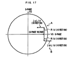
- the D-phase current Id in the same orientation of magnetic flux ⁇ is set to "0" and the Q-phase current Iq perpendicular to the D-phase current Id is controlled so as to follow the torque command.
- ⁇ represents an angular speed of the rotor
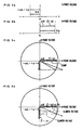
- the D-phase and Q-phase voltages at that time is shown in a vector diagram of FIG. 14.
- Vd Vlim ⁇ sin ⁇
- Vq Vlim ⁇ cos ⁇
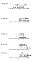
- FIG. 15a shows the relation between the D-phase command voltage and the current
- FIG. 15b shows the relation between the Q-phase command voltage and the current, when the composite voltage Vc does not exceed the voltage limit value Vlim.
- the D-phase current command to flow an invalid current is set to "0" and the current control is performed by the Q-phase current command.
- a negative voltage (- ⁇ L ⁇ Iq) is generated in the D phase due to the voltage interference in the motor.
- the D-phase command voltage Vd reaches the interference voltage (- ⁇ L ⁇ Iq) as shown in FIG. 15a, so that no current flows in the D phase. Therefore, any interference voltage due to the D-phase current does not appear in the Q phase.
- servomotor control has been the subject of many proposals including, for example, as made in: JP-06-085637 B; the Article "Analysis and implementation of a real-time predictive current controller for permanent-magnetic synchronous servodrives" published in IEEE Transactions on Industrial Electronics, Vol. 41, No. 1, February 1994; and in EP-A-0476588.
- a saturation process is performed to rewrite the value of an integrator in the D-phase current control loop only when the servomotor is in deceleration in the current control of the servomotor using the DQ conversion. If a voltage command is saturated in acceleration, a saturation process is performed to rewrite only an integrator in the Q-phase current control loop. As a result, an accelerating torque is increased and also the deceleration current control is stabilized when the voltage command is saturated.
- a large torque is necessary to sharply accelerate a servomotor in high-speed rotation.
- the vector sum of the D-phase and Q-phase voltage commands exceeds the voltage limit value of a power amplifier to be in saturation, the output of the power amplifier is restricted to a clamped voltage command so that the current control of the servomotor can not be performed.
- the saturation process is performed for the Q phase but not for the D phase, to rewrite a value of an integrator in the Q-phase current control loop.
- the saturation process for the Q phase restricts the value of the integrator in the current loop and prevents the maximum voltage command from being continuously outputted when the current command decreases, so as to stabilize the deceleration current control of the current loop after the voltage command is saturated.
- the D-phase voltage is outputted without restriction so as to control the D-phase current, which is produced by the voltage interference, to be zero and also increase the accelerating torque by increasing the Q-phase current.
- the saturation process is performed for both of the D and Q phases to rewrite the integrators in the current control loops for the D-phase and Q-phase.
- the value of the integrators of the current loop are thus restricted not to increase and also the maximum voltage command is prevented from being continuously outputted when the current command decreases, thus stabilizing the deceleration current control in the current loop after the voltage command is saturated.
- the saturation process is performed for the D phase since it is not necessary to control the D-phase current by the D-phase voltage.
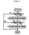
- Step T1 it is discriminated whether or not a voltage command is saturated. If the voltage command is not saturated, a current loop process rather than a saturation process is performed. If the voltage command is saturated, the procedure proceeds to Step T2 to perform a saturation process to rewrite an integrator based on the voltage command clamped with respect to the Q phase.
- Step T3 it is discriminated whether or not the servomotor is controlled to be accelerated. If the servomotor is to be accelerated, the current loop process is performed without performing the saturation process with respect to the D phase. If the servomotor is not to be accelerated, the procedure proceeds to Step T4 to perform the current loop process after the saturation process with respect to the D phase.
- FIG. 2 is a block diagram of a control system for an AC servomotor for carrying out the present invention, as it is divided into D-phase and Q-phase control systems.
- D-phase and Q-phase controllers are provided with an integral term 11, 12 (K1 is an integral gain) and a proportional term 13, 14 (K2 is a proportional gain), respectively, and the motor is represented by a resistance R and an inductance L.
- the D-phase and Q-phase controllers are provided with mutual interference terms 15, 16, respectively.
- the above arrangement of the control system is identical with that of the conventional control system as shown in FIG. 12.
- the D-phase integrator is rewritten only in deceleration by the saturation process, while the Q-phase integrator is rewritten in acceleration and deceleration by the saturation process, to thereby increase the acceleration torque in acceleration and also stabilize the current control for deceleration when the voltage command is saturated in acceleration and deceleration.
- FIGS. 3c and 3d respectively show a relation between the D-phase and Q-phase voltages according to the current control method of the present invention and the conventional current control method. Comparing the present method with the conventional method with respect to the Q-phase voltage, since no interference voltage ( ⁇ L ⁇ Iq) is produced in D phase in FIG. 3c according to the present invention, it is possible to take a component by the Q-phase current in the clamped voltage larger than that in FIG. 3d, according to the conventional method. Since the torque of the servomotor is proportional to the Q-phase current, an acceleration characteristic of the servomotor can be improved.
- the D-phase voltage Vd When the command voltage is saturated, the D-phase voltage Vd is clamped so that a negative D-phase current Id flows as shown in FIG. 5b, thus decreasing the Q-phase voltage Vq as shown in FIG. 5c. According to the increase of the D-phase current, the D-phase and Q-phase voltages Vd and Vq decrease to eliminate the voltage saturation.
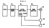
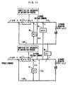
- FIG. 6 is a block diagram of a servo-motor control system for carrying out the method of the present invention.
- the architecture of the servo-motor control system is identical with the conventional digital servo control system and will therefore be generally described here.
- reference number 20 designates a computerized numerical control unit (CNC); 21, a shared RAM; 22, a digital servo circuit having a processor (CPU), ROM, RAM, etc.; 23, a power amplifier such as a transistor inverter; M, an AC servomotor; 24, an encoder for generating pulses in response to rotation of the AC servomotor M; and 25, a rotor position detector for detecting a rotor phase.
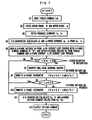
- FIG. 7 is a flowchart of a current loop control process to be performed in every predetermined period by the processor of the digital servo circuit 22.
- the processor of the digital servo circuit 22 reads a position command (or a speed command) from the numerical control unit (CNC) via the shared RAM 21 to perform a position loop process and a speed loop process.
- CNC numerical control unit
- the processor reads a torque command Iq* outputted from the speed loop process (Step S1) and fetches a rotor phase ⁇ from the rotor position detector 25 (Step S2).
- the processor fetches the actual currents Iu and Iv of U and V phases, which are detected by a current detector (step S3), and calculates D-phase and Q-phase currents Id, Iq by the DQ conversion using the fetched U-phase and V-phase actual currents Iu, Iv and the rotor phase ⁇ (Step S4).
- An ordinary current loop process (proportional-plus-integral control) is performed to obtain a D-phase command voltage Vd, using the D-phase current Id as a feedback current and the D-phase current command of "0".
- a current loop process is performed to obtain a Q-phase voltage command Vq, using the torque command read in Step S1 as the Q-phase current command and the Q-phase current value Iq calculated in Step S4 as a feedback current (Step S5).
- Step S6 it is discriminated whether or not a composite vector Vc of the D-phase and Q-phase command voltages Vd, Vq obtained in Step S5 exceeds a DC link voltage Vdc, which is the voltage limit value Vlim. Namely, it is discriminated whether or not the value of (Vd 2 + Vq 2 ) is larger than the value of Vdc 2 (Step S6).
- Step S11 the procedure proceeds to Step S11 where the D-phase and Q-phase command voltages Vd, Vq calculated in Step S5 are converted by DQ conversion to obtain and output U-Phase, V-phase and Q-phase voltage command values (Step S11).
- Step S6 when the composite vector Vc exceeds the DC link voltage Vdc, it is judged that the command voltage is saturated and a proportional-plus-integral control is performed to calculate a Q-phase voltage Vq (Step S7). Then, the processor rewrite the value of the Q-phase integrator to be (Vqmax + K2 ⁇ Iqfb)/k1, to perform a Q-phase saturation process (Step S8).
- Step S9 it is discriminated whether the servomotor is in acceleration or deceleration based on the sign of ⁇ Iq (Step S9).
- Step S9 if the motor is rotating forward ( ⁇ >0) and the torque command Iq* is positive, or if the motor is rotating backward ( ⁇ 0) and the torque command Iq* is negative, it is judged that the motor is in acceleration, and the procedure proceeds to Step S11 where U-phase, V-phase and W-phase voltage command values are obtained.
- Step S9 if the motor is rotating forward ( ⁇ >0) and the torque command Iq* is negative, or if the motor is rotating backward ( ⁇ 0) and the torque command Iq* is positive, it is judged that the motor is in deceleration and the processor rewrites the value of the D-phase integrator as (Vdmax + K2 ⁇ Idfb)/k1, to perform a D-phase saturation process (Step S10), and then the procedure proceeds to Step S11 where U-phase, V-phase and W-phase voltage command values are obtained.
- the Q-phase saturation process is also performed.
- the obtained D-phase and Q-phase voltages Vd, Vq are converted by DQ conversion to calculate and output U-phase, V-phase and W-phase voltage command values (Steps S11, S12), to terminate the current loop process of one period.
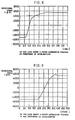
- FIGS. 8 and 9 show response results according to the conventional method and the method of the present invention, respectively, in which the same speed command is set such that the motor is accelerated stepwise from -1500 rpm to + 5000 rpm.
- the response characteristic is of approximately 100 ms from -5000 rpm to +3000 rpm and then it takes approximately 600 ms to reach +5000 rpm as the torque drops.
- the response characteristic is of approximately 100 ms from -5000 rpm to +3000 rpm likewise the conventional method, but it takes only approximately 200 ms to reach +5000 rpm as the torque slightly drops, thus improving the acceleration characteristic.
Landscapes
- Engineering & Computer Science (AREA)
- Power Engineering (AREA)
- Control Of Ac Motors In General (AREA)
Claims (6)
- Verfahren zur Regelung eines 3-Phasen-Stroms (Iu, Iv, Iw) in einem 3-Phasen-Servomotor (M) durch Erteilen von D-Phasen- und Q-Phasen-Spannungsbefehlen (Vd, Vq), die in 3-Phasen-Spannungsbefehle (Vu, Vv, Vw) umgewandelt werden, die einem Leistungsverstärker (6) zugeführt werden, der den 3-Phasen-Strom (Iu, Iv, Iw) dem 3-Phasen-Servomotor (M) zuführt, wobei die D-Phasen- und Q-Phasen-Spannungsbefehle (Vd, Vq) durch Umwandeln der Istwerte des Servomotor-3-Phasen-Stroms (Iu, Iv, Iw) in Gleichstromwerte (Id, Iq) erzeugt werden, die D- und Q-Phasen haben, wobei der D-Phasen-Stromwert (Id) die gleiche Orientierung wie der 3-Phasen-Servomotormagnetfluss () hat und für den befohlen wird, dass er zu Null wird, um zu dem D-Phasen-Spannungsbefehl (Vd) zu führen, der von einer D-Phasen-Stromregelungseinrichtung (5d) erteilt wird, und der Q-Phasen-Stromwert (Iq) senkrecht zu dem D-Phasen-Stromwert (Id) orientiert ist und derart geregelt wird, dass er einem 3-Phasen-Servomotordrehmomentbefehl folgt, um dadurch zu dem Q-Phasen-Spannungsbefehl (Vq) zu führen, der von einer Q-Phasen-Stromregelungseinrichtung (5q) erteilt wird, welches Verfahren gekennzeichnet ist durch Schritte zum(a) Unterscheiden, ob die Spannungsbefehle über eine maximale Spannung (Vdc), die der Leistungsverstärker (6) auszugeben in der Lage ist, hinaus gesättigt sind oder nicht,(b) Unterscheiden, ob sich der 3-Phasen-Servomotor (M) in einem Zustand einer Beschleunigung oder einer Verzögerung befindet, und(c) Überschreiben des Inhalts eines Integrators der D-Phasen-Stromregelungseinrichtung (5d) nur dann, wenn in Schritt (a) unterschieden ist, dass die Spannungsbefehle gesättigt sind, und in Schritt (b) unterschieden ist, dass sich der 3-Phasen-Servomotor (M) in einem Zustand einer Verzögerung befindet.
- Verfahren zur Regelung eines 3-Phasen-Stroms (Iu, Iv, Iw) in einem 3-Phasen-Servomotor (M) durch Erteilen von D-Phasen- und Q-Phasen-Spannungsbefehlen (Vd, Vq), die in 3-Phasen-Spannungsbefehle (Vu, Vv, Vw) umgewandelt werden, die einem Leistungsverstärker (6) zugeführt werden, der den 3-Phasen-Strom (Iu, Iv, Iw) dem 3-Phasen-Servomotor (M) zuführt, wobei die D-Phasen- und Q-Phasen-Spannungsbefehle (Vd, Vq) durch Umwandeln der Istwerte des Servomotor-3-Phasen-Stroms (Iu, Iv, Iw) in Gleichstromwerte (Id, Iq) erzeugt werden, die D- und Q-Phasen haben, wobei der D-Phasen-Stromwert (Id) die gleiche Orientierung wie der 3-Phasen-Servomotormagnetfluss () hat und für den befohlen wird, dass er zu Null wird, um zu dem D-Phasen-Spannungsbefehl (Vd) zu führen, der von einer D-Phasen-Stromregelungseinrichtung (5d) erteilt wird, und der Q-Phasen-Stromwert (Iq) senkrecht zu dem D-Phasen-Stromwert (Id) orientiert ist und derart geregelt wird, dass er einem 3-Phasen-Servomotordrehmomentbefehl folgt, um dadurch zu dem Q-Phasen-Spannungsbefehl (Vq) zu führen, der von einer Q-Phasen-Stromregelungseinrichtung (5q) erteilt wird, welches Verfahren gekennzeichnet ist durch Schritte zum(a) Unterscheiden, ob die Spannungsbefehle über eine maximale Spannung (Vdc), die der Leistungsverstärker (6) auszugeben in der Lage ist, hinaus gesättigt sind oder nicht,(b) Unterscheiden, ob sich der 3-Phasen-Servomotor (M) in einem Zustand einer Beschleunigung oder einer Verzögerung befindet, und(c) Überschreiben des Inhalts eines Integrators der Q-Phasen-Stromregelungseinrichtung (5q) nur dann, wenn in Schritt (a) unterschieden ist, dass die Spannungsbefehle gesättigt sind, und in Schritt (b) unterschieden ist, dass sich der 3-Phasen-Servomotor (M) in einem Zustand einer Beschleunigung befindet.
- Verfahren zur Stromregelung für einen 3-Phasen-Servomotor (M) nach Anspruch 1, bei dem Schritt (c) einen Schritt enthält zum Überschreiben des Inhalts des Integrators der D-Phasen-Stromregelungseinrichtung (5d) derart, dass die D-Phasen-Stromregelungseinrichtung (5d) einen Spannungsbefehl (Vd) erteilt, um den Leistungsverstärker (6) zu veranlassen, die maximale Spannung (Vdc) auszugeben.
- Verfahren zur Stromregelung für einen 3-Phasen-Servomotor (M) nach Anspruch 2, bei dem Schritt (c) einen Schritt enthält zum Überschreiben des Inhalts des Integrators der Q-Phasen-Stromregelungseinrichtung (5q) derart, dass die Q-Phasen-Stromregelungseinrichtung (5q) einen Spannungsbefehl (Vq) erteilt, um den Leistungsverstärker (6) zu veranlassen, die maximale Spannung (Vdc) auszugeben.
- Verfahren zur Stromregelung für einen 3-Phasen-Servomotor (M) nach einem der vorhergehenden Ansprüche, bei dem Schritt (a) einen Schritt enthält zum Unterscheiden, ob eine Vektorsumme der D-Phasen- und Q-Phasen-Spannungsbefehle (Vd, Vq) die maximale Spannung des Leistungsverstärkers (6) übersteigt oder nicht.
- Verfahren zur Stromregelung für einen 3-Phasen-Servomotor (M) nach einem der vorhergehenden Ansprüche, bei dem Schritt (b) einen Schritt enthält zum Unterscheiden auf der Grundlage der Drehrichtung des 3-Phasen-Servomotors (M) und des Vorzeichens des Q-Phasen-Strombefehls, ob sich der 3-Phasen-Servomotor (M) in einem Zustand einer Beschleunigung oder einer Verzögerung befindet.
Applications Claiming Priority (4)
| Application Number | Priority Date | Filing Date | Title |
|---|---|---|---|
| JP26801095 | 1995-09-22 | ||
| JP26801095A JP3683313B2 (ja) | 1995-09-22 | 1995-09-22 | サーボモータの電流制御方法 |
| JP268010/95 | 1995-09-22 | ||
| PCT/JP1996/002745 WO1997011525A1 (fr) | 1995-09-22 | 1996-09-24 | Procede de commande d'intensite dans un servo-moteur |
Publications (3)
| Publication Number | Publication Date |
|---|---|
| EP0798848A1 EP0798848A1 (de) | 1997-10-01 |
| EP0798848A4 EP0798848A4 (de) | 1998-11-18 |
| EP0798848B1 true EP0798848B1 (de) | 2003-03-05 |
Family
ID=17452659
Family Applications (1)
| Application Number | Title | Priority Date | Filing Date |
|---|---|---|---|
| EP96931294A Expired - Lifetime EP0798848B1 (de) | 1995-09-22 | 1996-09-24 | Verfahren zur steuerung des stroms eines servomotor |
Country Status (5)
| Country | Link |
|---|---|
| US (1) | US5955863A (de) |
| EP (1) | EP0798848B1 (de) |
| JP (1) | JP3683313B2 (de) |
| DE (1) | DE69626492T2 (de) |
| WO (1) | WO1997011525A1 (de) |
Families Citing this family (13)
| Publication number | Priority date | Publication date | Assignee | Title |
|---|---|---|---|---|
| US6201720B1 (en) | 2000-02-18 | 2001-03-13 | Powerware Corporation | Apparatus and methods for space-vector domain control in uninterruptible power supplies |
| US6963182B2 (en) * | 2002-11-29 | 2005-11-08 | Toyoda Koki Kabushiki Kaisha | Motor control device and motor control method |
| US7102305B2 (en) * | 2003-05-22 | 2006-09-05 | Toyoda Koki Kabushiki Kaisha | Apparatus and method for controlling motor |
| JP2005219133A (ja) * | 2004-02-03 | 2005-08-18 | Fanuc Ltd | ロボット用サーボモータ制御装置およびロボット |
| IT1393871B1 (it) | 2009-04-22 | 2012-05-11 | Ansaldo Energia Spa | Metodo di controllo vettoriale per motori elettrici |
| FR2976746B1 (fr) * | 2011-06-15 | 2015-08-07 | Renault Sa | Procede et dispositif de commande d'un groupe motopropulseur electrique a commandes decouplees |
| GB201111602D0 (en) * | 2011-07-06 | 2011-08-24 | Nidec Sr Drives Ltd | Control of electrical machines |
| JP5620535B2 (ja) * | 2013-03-19 | 2014-11-05 | ファナック株式会社 | 電圧飽和を検出する電動機の制御システム |
| FR3006129B1 (fr) * | 2013-05-27 | 2015-05-01 | Renault Sa | Procede de commande d'une machine electrique synchrone, systeme correspondant et vehicule automobile comprenant le systeme |
| FR3012270B1 (fr) * | 2013-10-17 | 2017-04-21 | Renault Sas | Procede et systeme de commande d'une machine electrique d'un vehicule automobile |
| JP5890465B2 (ja) * | 2014-05-08 | 2016-03-22 | ファナック株式会社 | モータの動力線断線、またはモータ用電力変換装置のパワー素子異常を検出するモータ制御装置 |
| FR3106458B1 (fr) | 2020-01-20 | 2021-12-17 | Safran Electrical & Power | Procédé de commande d’une machine électrique |
| CN113267995B (zh) * | 2021-04-27 | 2022-08-26 | 长春同泽科技有限公司 | 一种驱动控制装置、控制方法及矿井运输车 |
Family Cites Families (11)
| Publication number | Priority date | Publication date | Assignee | Title |
|---|---|---|---|---|
| JPS63274385A (ja) * | 1987-04-30 | 1988-11-11 | Fanuc Ltd | サ−ボモ−タの速度制御装置 |
| JPH0685637B2 (ja) * | 1987-08-21 | 1994-10-26 | 富士電機株式会社 | 誘導電動機のベクトル制御装置 |
| GB2243464B (en) * | 1990-03-23 | 1994-02-23 | Toyoda Machine Works Ltd | Digital servo-control apparatus |
| JP2892802B2 (ja) * | 1990-09-21 | 1999-05-17 | 株式会社日立製作所 | 電動機の速度制御装置 |
| JPH04302522A (ja) * | 1991-03-29 | 1992-10-26 | Hitachi Ltd | 演算回路及びこれを用いた適応フィルタ並びにエコーキャンセラ |
| JPH05336789A (ja) * | 1992-06-01 | 1993-12-17 | Fanuc Ltd | モータの制御方式 |
| JPH0685637A (ja) * | 1992-08-31 | 1994-03-25 | Ricoh Res Inst Of Gen Electron | 合成スイッチング回路 |
| EP0633653B1 (de) * | 1993-07-09 | 1995-09-27 | Siemens Aktiengesellschaft | Stromregelverfahren und Vorrichtung für einen spannungseinprägenden Umrichter |
| JPH07104856A (ja) * | 1993-10-01 | 1995-04-21 | Fanuc Ltd | 振動制御方法 |
| US5670854A (en) * | 1994-12-14 | 1997-09-23 | Matsushita Electric Industrial Co., Ltd. | Control system for an induction motor |
| JP3751991B2 (ja) * | 1994-12-26 | 2006-03-08 | ファナック株式会社 | Acサーボモータの電流制御方法 |
-
1995
- 1995-09-22 JP JP26801095A patent/JP3683313B2/ja not_active Expired - Fee Related
-
1996
- 1996-09-24 DE DE69626492T patent/DE69626492T2/de not_active Expired - Fee Related
- 1996-09-24 WO PCT/JP1996/002745 patent/WO1997011525A1/ja not_active Ceased
- 1996-09-24 US US08/836,732 patent/US5955863A/en not_active Expired - Fee Related
- 1996-09-24 EP EP96931294A patent/EP0798848B1/de not_active Expired - Lifetime
Also Published As
| Publication number | Publication date |
|---|---|
| DE69626492D1 (de) | 2003-04-10 |
| US5955863A (en) | 1999-09-21 |
| JP3683313B2 (ja) | 2005-08-17 |
| WO1997011525A1 (fr) | 1997-03-27 |
| DE69626492T2 (de) | 2003-09-25 |
| EP0798848A1 (de) | 1997-10-01 |
| EP0798848A4 (de) | 1998-11-18 |
| JPH0993999A (ja) | 1997-04-04 |
Similar Documents
| Publication | Publication Date | Title |
|---|---|---|
| EP0836270B1 (de) | Verfahren zur regelung des stromes in einem servomotor | |
| EP0793338B1 (de) | Verfahren zur stromregelung von servomotoren | |
| EP1237274B1 (de) | Regler für einen Elektromotor | |
| EP1276225B1 (de) | Motorsteuerung zur Reduzierung der Oberschwingungsströme | |
| JP3722048B2 (ja) | モーター制御装置 | |
| US6992448B2 (en) | Motor control apparatus | |
| EP0798848B1 (de) | Verfahren zur steuerung des stroms eines servomotor | |
| JP3527207B2 (ja) | モータ制御装置 | |
| EP1562283A1 (de) | Regelvorrichtung eines Servomotors für einen Roboter und Roboter mit einer solchen Vorrichtung | |
| JP3383682B2 (ja) | Acサーボモータの電流制御方法 | |
| EP0751613B1 (de) | Verfahren zur Steuerung des Stroms eines Servomotors | |
| EP0616417B1 (de) | Regelungsverfahren für einen wechselstrommotor | |
| JPH0614592A (ja) | Acサーボモータの加速度制御方式 | |
| JP3751991B2 (ja) | Acサーボモータの電流制御方法 | |
| JP3534722B2 (ja) | モータの制御装置 | |
| JP2011072190A (ja) | 交流電動機の制御装置 | |
| JP2002325498A (ja) | 交流電動機の制御装置 | |
| JP3783641B2 (ja) | モーター制御装置 | |
| JPH1118498A (ja) | サーボモータ制御装置 | |
| JP7629818B2 (ja) | 交流電動機の駆動制御装置および駆動制御方法 | |
| JPH09285200A (ja) | サーボモータの電流制御方式 | |
| JPH0732636B2 (ja) | Pwmインバータの交流出力電圧制御装置 |
Legal Events
| Date | Code | Title | Description |
|---|---|---|---|
| PUAI | Public reference made under article 153(3) epc to a published international application that has entered the european phase |
Free format text: ORIGINAL CODE: 0009012 |
|
| 17P | Request for examination filed |
Effective date: 19970612 |
|
| AK | Designated contracting states |
Kind code of ref document: A1 Designated state(s): DE |
|
| A4 | Supplementary search report drawn up and despatched |
Effective date: 19980929 |
|
| AK | Designated contracting states |
Kind code of ref document: A4 Designated state(s): DE |
|
| 17Q | First examination report despatched |
Effective date: 20001026 |
|
| GRAG | Despatch of communication of intention to grant |
Free format text: ORIGINAL CODE: EPIDOS AGRA |
|
| GRAG | Despatch of communication of intention to grant |
Free format text: ORIGINAL CODE: EPIDOS AGRA |
|
| GRAH | Despatch of communication of intention to grant a patent |
Free format text: ORIGINAL CODE: EPIDOS IGRA |
|
| GRAH | Despatch of communication of intention to grant a patent |
Free format text: ORIGINAL CODE: EPIDOS IGRA |
|
| GRAA | (expected) grant |
Free format text: ORIGINAL CODE: 0009210 |
|
| AK | Designated contracting states |
Designated state(s): DE |
|
| REF | Corresponds to: |
Ref document number: 69626492 Country of ref document: DE Date of ref document: 20030410 Kind code of ref document: P |
|
| PLBE | No opposition filed within time limit |
Free format text: ORIGINAL CODE: 0009261 |
|
| STAA | Information on the status of an ep patent application or granted ep patent |
Free format text: STATUS: NO OPPOSITION FILED WITHIN TIME LIMIT |
|
| 26N | No opposition filed |
Effective date: 20031208 |
|
| PGFP | Annual fee paid to national office [announced via postgrant information from national office to epo] |
Ref country code: DE Payment date: 20081002 Year of fee payment: 13 |
|
| PG25 | Lapsed in a contracting state [announced via postgrant information from national office to epo] |
Ref country code: DE Free format text: LAPSE BECAUSE OF NON-PAYMENT OF DUE FEES Effective date: 20100401 |