EP0798166B1 - Dichtung und Verfahren zum Montieren einer Dichtung - Google Patents
Dichtung und Verfahren zum Montieren einer Dichtung Download PDFInfo
- Publication number
- EP0798166B1 EP0798166B1 EP97105269A EP97105269A EP0798166B1 EP 0798166 B1 EP0798166 B1 EP 0798166B1 EP 97105269 A EP97105269 A EP 97105269A EP 97105269 A EP97105269 A EP 97105269A EP 0798166 B1 EP0798166 B1 EP 0798166B1
- Authority
- EP
- European Patent Office
- Prior art keywords
- locking
- grommet
- turnup
- locking groove
- tubular portion
- Prior art date
- Legal status (The legal status is an assumption and is not a legal conclusion. Google has not performed a legal analysis and makes no representation as to the accuracy of the status listed.)
- Expired - Lifetime
Links
- 238000000034 method Methods 0.000 title claims description 7
- 238000003780 insertion Methods 0.000 claims description 13
- 230000037431 insertion Effects 0.000 claims description 13
- 238000010276 construction Methods 0.000 description 3
- 229920001971 elastomer Polymers 0.000 description 3
- 238000000638 solvent extraction Methods 0.000 description 2
- 101100008050 Caenorhabditis elegans cut-6 gene Proteins 0.000 description 1
- 244000208734 Pisonia aculeata Species 0.000 description 1
- 230000008602 contraction Effects 0.000 description 1
- 230000007423 decrease Effects 0.000 description 1
- 230000001419 dependent effect Effects 0.000 description 1
- 239000000806 elastomer Substances 0.000 description 1
- 238000004519 manufacturing process Methods 0.000 description 1
- 239000000463 material Substances 0.000 description 1
- 230000004048 modification Effects 0.000 description 1
- 238000012986 modification Methods 0.000 description 1
- 238000007789 sealing Methods 0.000 description 1
- 229920003002 synthetic resin Polymers 0.000 description 1
- 239000000057 synthetic resin Substances 0.000 description 1
- XLYOFNOQVPJJNP-UHFFFAOYSA-N water Substances O XLYOFNOQVPJJNP-UHFFFAOYSA-N 0.000 description 1
Images


Classifications
-
- B—PERFORMING OPERATIONS; TRANSPORTING
- B60—VEHICLES IN GENERAL
- B60R—VEHICLES, VEHICLE FITTINGS, OR VEHICLE PARTS, NOT OTHERWISE PROVIDED FOR
- B60R16/00—Electric or fluid circuits specially adapted for vehicles and not otherwise provided for; Arrangement of elements of electric or fluid circuits specially adapted for vehicles and not otherwise provided for
- B60R16/02—Electric or fluid circuits specially adapted for vehicles and not otherwise provided for; Arrangement of elements of electric or fluid circuits specially adapted for vehicles and not otherwise provided for electric constitutive elements
- B60R16/0207—Wire harnesses
- B60R16/0215—Protecting, fastening and routing means therefor
- B60R16/0222—Grommets
Definitions
- the present invention relates to a grommet mountable into a hole formed in a body panel of a vehicle with a wiring harness inserted therethrough and is particularly designed to improve the mounting operability of a grommet. Furthermore the present invention relates to a method for mounting a grommet into a body panel, in particular of a vehicle.
- an automotive wiring harness W/H When an automotive wiring harness W/H is arranged by being inserted through a through hole 1a formed in a body panel of a vehicle (e.g. a dashboard partitioning an engine compartment A and a passenger compartment B) as shown in FIG. 6A, a small diameter tubular portion 2a of a grommet 2 made of rubber with the wiring harness W/H inserted therethrough is inserted through the through hole 1a from the engine compartment A side to the passenger compartment B side, and a groove 2c formed in the outer surface of a large diameter portion 2b is fitted to the edge of the through hole 1a. In this way, the grommet 2 is mounted in the through hole 1a of the body panel 1.
- a small diameter tubular portion 2a of a grommet 2 made of rubber with the wiring harness W/H inserted therethrough is inserted through the through hole 1a from the engine compartment A side to the passenger compartment B side, and a groove 2c formed in the outer surface of a large diameter portion 2b is fitted to the edge of the through
- a lip portion 2d formed at its lending end may be deformed by the edge of the through hole 1a, thereby entering the groove 2c to close it.
- the grommet 2 cannot be securely mounted and a water leak may be caused by poor sealability.
- the grommet 2 is pulled back after being inserted into the through hole 1a to the rear end of the large diameter portion 2b so as to prevent the above deformation of the lip portion 2d.
- this requires a push-in operation and a pull-back operation which are performed in two directions, resulting in poor mounting operability.
- the present invention was developed to solve the above problems and an object thereof is to provide a grommet and a method for mounting a grommet, which allow the grommet to be easily and inexpensively mountable on a body panel preferably of a vehicle, in particular by being inserted in one direction.
- the grommet comprising: a first (preferably small diameter) tubular portion, a second (preferably large diameter) tubular portion, a locking groove being fittable to a body panel, in particular of a vehicle, a turnup portion, in particular being folded or foldable back from an outer radial end of the second, preferably large diameter tubular portion toward the first, preferably small diameter tubular portion, wherein the locking groove is formed in an outer surface of the turnup portion located radially outside of the second, preferably large diameter tubular portion, and wherein the locking groove has a variable cross section depending on whether the turnup portion is in a first inserting position or a second fitting position, the locking groove in its inserting position being arranged at the front end of the grommet, preferably being biased toward its fitting position, when the turnup portion is in its first position, thereby allowing the grommet to be inserted into the body panel, the locking groove being restored to or positioned in its fitting position, when the turnup portion is in its second position, so as to be fittable to the
- the insertability of the grommet into the body panel of e.g. a vehicle depends upon the positioning of the foldup portion.
- the locking groove is adapted such that it varies its configuration or shape such that depending upon the configuration of a separate portion of the grommet is insertable (inserting position) or fittable (fitting position) into the body panel.
- the foldup portion when the foldup portion is in its first position the locking groove is in its inserting position, while when the foldup portion is in its second position, the locking groove is in its fitting position.
- the foldup portion has not necessarily to be folded or foldable back.
- the locking groove comes to have a substantially L-shaped cross section, when the turnup portion is in its first position, and wherein the locking groove is restored to have a substantially U-shaped cross section, when the turnup portion is in its second position.
- deformation facilitating means are provided so as to facilitate the deforming and restoring action of the grommet, when the turnup portion is shifted between its first and second positions, wherein cuts are circumferentially formed at intervals in the front surface so as to facilitate the deformation of the thick portion.
- the turnup portion is located or arranged in its first and second positions being spaced along the axial direction (or at different axial positions), in particular with respect to the first, preferably small diameter portion.
- the grommet further comprises locking means for holding or locking the turnup portion in its first position or its second position, wherein the locking means preferably comprises:
- the turnup portion when the locking portion is engaged with the locking stepped portion after pulling the first, preferably small diameter tubular portion back to locate the locking stepped portion more backward than the locking portion, the turnup portion is in its first position; and when the locking portion is disengaged from the locking stepped portion, in particular after the insertion, the turnup portion is in its second position.
- the radially inwardly projecting end of the locking portion is located more radially inward than the radially outwardly projecting end of the locking stepped portion in a normal state of the grommet, in particular where no force is exerted thereon; when the first, preferably small diameter tubular portion is pulled back to make the second, preferably large diameter tubular portion radially smaller, the radially outwardly projecting end of the locking stepped portion is located more radially inward than the radially inwardly projecting end of the locking portion; and/or when a pulling force acting on the first, preferably small diameter tubular portion is released, the locking stepped portion is returned to its front position.
- a portion of the grommet extending from the second, preferably large diameter tubular portion through the front end surface to a position of the turnup portion where the locking groove is formed is substantially thicker than the other parts of the grommet.
- first, preferably small diameter tubular portion, the second, preferably large diameter tubular portion, the locking groove and the turnup portion are integrally or unitarily formed.
- a method for mounting or fitting a grommet according to the invention, into or to a body panel, in particular of a vehicle comprising the steps of:
- the turnup portion displacing steps comprise the step of substantially axially shifting the turnup portion at least between the first position and the second position.
- the step of varying the cross section of the locking groove toward a fitting position thereof is supported by a biasing or restoring force biasing the locking groove toward its fitting position.
- the turnup portion displacing step comrises the step of axially pushing or shifting or moving the grommet onto the body panel, in particular an edge of an opening thereof, to displce the turnup portion from the first position to the second position.
- a grommet which is provided with a hollow wiring harness insertion portion extending along axes of small and large diameter tubular portions, and is mountable by being inserted into a hole formed in a body panel of a vehicle in one direction after a wiring harness is inserted into the wiring harness insertion portion and by engaging a locking groove formed in the outer surface of the large diameter tubular portion with the edge of the hole of the body panel, comprising:
- the turnup portion of the large diameter tubular portion is pulled back while the locking groove formed therein is opened to have an L-shaped cross section, with the result that the large diameter tubular portion is radially contracted.
- the locking stepped portion is located more backward than the locking portion, the locking portion is engaged with the locking stepped portion, thereby temporarily preventing the large diameter tubular portion from restoring to have a larger diameter.
- the locking groove is restored to have a U-shaped cross section as the turnup portion is restored to its front position, thereby allowing the radial expansion of the large diameter tubular portion.
- the locking groove is automatically secured to the edge of the hole in the body panel. Therefore, the grommet can easily be mounted in the hole in the body panel only in one operation by being inserted from an insertion side in one direction.
- the locking groove is opened to have an L-shaped cross section by pulling back the small diameter tubular portion, thereby making the large diameter tubular portion radially smaller.
- the radially expansive restoration of the large diameter tubular portion is temporarily hindered by the engagement of the locking portion and the locking stepped portion, holding the grommet in this locked position. Accordingly, the locking groove of the large diameter tubular portion can be smoothly inserted into the hole in the body panel.
- the locking groove is restored to have a U-shaped cross section, and the large diameter tubular portion is restored to have a larger diameter again. Therefore, the locking groove can automatically be fitted to the edge of the hole in the body panel.
- the grommet can be easily mounted in the hole in the body panel only by being inserted from the insertion side with a small force, improving mounting operability. Further, since the grommet has a one-piece construction unlike the prior art grommet having a two-part construction, it can be produced at a reduced cost.
- the radially inwardly projecting end of the locking portion is located more radially inward than the radially outwardly projecting end of the locking stepped portion in a normal state of the grommet where no force is exerted thereon.
- the radially outwardly projecting end of the locking stepped portion is located more radially inward than the radially inwardly projecting end of the locking portion.
- the locking stepped portion is returned to its first position, preferably to its front position.
- the locking portion can automatically be engaged with the locking stepped portion only by pulling back the small diameter tubular portion until the locking stepped portion moves beyond the locking portion.
- the locking portion can automatically be engaged with the locking stepped portion only by pulling back the small diameter tubular portion until the locking stepped portion moves beyond the locking portion.
- a portion of the grommet extending from the large diameter tubular portion through the front end surface to a position of the turnup portion where the locking groove is formed is thicker than the other parts of the grommet, and cuts are circumferentially formed at intervals in the front surface so as to facilitate the deformation of the thick portion .
- a grommet for mounting to a body panel, said grommet having opposed front and rear ends and comprising:
- the invention further provides a grommet for mounting in an aperture of a body panel, said grommet being unitarily formed from a resiliently deformable material and having opposed front and rear ends, said grommet comprising:
- a through hole 6a is formed in a body panel 6 partitioning an engine compartment A and a passenger compartment B of an automotive vehicle, and a tubular bar ring 6d projects at the edge of the through hole 6a on a surface 6c at the side of the engine compartment A (insertion side).
- a grommet 5 made of rubber or elastomer includes, from its rear end, a small diameter tubular portion 5a, a medium diameter tubular portion 5b continuous with the front end of the small diameter tubular portion 5a, a large diameter tubular portion 5c continuous with the front end of the medium diameter tubular portion 5b, and a turnup portion 5d substantially folded or foldable back from the radial outer end of the large diameter tubular portion 5c toward the small diameter tubular portion 5a.
- a hollow portion extending along axes of the respective tubular portions 5a to 5c acts as a wiring harness insertion portion.
- a tape or the like sealing means 7 is wound around the outer surface of the small diameter tubular portion 5a as well as the outer surface of the wiring harness W/H, thereby fixing the grommet 5 to the wiring harness W/H.
- a locking groove 5e having preferably a substantially U-shaped cross section which is to be fitted to the edge of the through hole 6a of the body panel 6 is formed in the outer surface of the turnup portion 5d of the large diameter tubular portion 5c of the grommet 5, dividing the turnup portion 5d into a front portion 5m and a rear portion 5n.
- a projection 5f is provided on the bottom surface of the locking groove 5e to improve sealability by elastically coming into contact with the edge of the through hole 6a.
- the opposite side walls of the locking groove 5e are slightly inclined inward to improve sealability by elastically coming into contact with opposite surfaces 6c, 6e of the body panel 6.
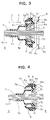
- a notch 5i is formed in the inner surface of the turnup portion 5d located more backward than the locking groove 5e. Because of the presence of the notch 5i, as shown in FIG. 4, the front portion 5m of the turnup portion 5d can be pulled open so that the rear portion 5n and the bottom surface of the locking groove 5e form a substantially L-shaped cross section.
- a locking portion 5g projecting radially inward.
- a locking stepped portion 5h whose outer end is located more radially outward than the inner end of the locking portion 5g is provided in a position substantially corresponding to the locking groove 5e.
- V- or spearhead-shaped cuts 5j are circumferentially formed, in particular radially arranged, at preferably equal intervals (e.g. 22.5°) and a circumferentially continuous cut 5k having a V-shaped cross section is so formed as to intersect substantially with the middle parts of the cuts 5j.
- the thick portion of the large diameter tubular portion 5c is easily deformable because of the presence of the cuts 5j and 5k. Accordingly, the small diameter tubular portion 5a can be pulled with a small force.
- the large diameter tubular portion 5c tries to restore forward due to the restoring force of the turnup portion 5d.
- the locking portion 5g is automatically engaged with the locking stepped portion 5h as shown in FIG. 3, the radially expansive restoration of the large diameter tubular portion 5c is temporarily hindered, i.e. temporarily held in this position.
- the locking groove 5e is held open and the outer diameter of the front portion 5m is held smaller than the diameter of the through hole 6a as shown in FIG. 3. In this state, the front portion 5m can be smoothly inserted into the through hole 6a of the body panel 6 from the engine compartment A side.
- the front portion 5m restores its shape to have an original diameter while rotating as the pulling force decreases.
- the locking groove 5e restores its shape to have a U-shaped cross section and the large diameter tubular portion 5c radially expands again as shown in FIG. 4, with the result that the locking groove 5e is automatically fitted to the edge of the through hole 6a of the body panel 6.
- the grommet 5 can be easily mounted into the through hole 6a of the body panel 6 by being inserted with a small force in one direction from the engine compartment A side after the locking portion 5g is engaged with the locking stepped portion 5h to temporarily prevent the radially expansive restoration of the large diameter tubular portion 5c.
- the medium diameter tubular portion 5b is provided between the small and large diameter tubular portions 5a and 5c of the grommet 5 in this embodiment, it may be omitted and the large diameter tubular portion 5b may be formed such that the diameter thereof gradually increases from the small diameter tubular portion 5a as shown in FIG. 5.
Landscapes
- Engineering & Computer Science (AREA)
- Mechanical Engineering (AREA)
- Insulating Bodies (AREA)
- Installation Of Indoor Wiring (AREA)
Claims (8)
- Durchgangstülle bzw. Durchführungshülse bzw. Dichtung (5) umfassend:einen ersten röhrenförmigen Abschnitt (5a),einen zweiten röhrenförmigen Abschnitt (5c),eine Verriegelungs- bzw. Verrastungsrille bzw. -nut (5e), welche paßbar ist an eine Körperverkleidung bzw. Karosseriebauteil bzw. -blech bzw. -blechteil (6), insbesondere eines Fahrzeugs,einen Aufschlag- bzw. Umschlagabschnitt (5d),wobei die Verriegelungsrille (5e) ausgebildet in einer äußeren Fläche bzw. Oberfläche des Umschlagabschnitts (5d), welcher radial außen von dem zweiten röhrenförmigen Abschnitt (5c) angeordnet ist, und wobei die Verriegelungsrille (5e) einen variablen Querschnitt aufweist, abhängig davon, ob der Umschlagabschnitt (5d) sich in einer ersten Einführposition (Fig. 3) oder einer zweiten Paßposition (Figuren 1 und 4) befindet, wobei die Verriegelungsrille (5e) in ihrer ersten Einführposition (Fig. 3) angeordnet ist an dem vorderen Ende der Durchgangstülle (5), wenn der Umschlagabschnitt (5d) sich in seiner ersten Position befindet (Fig. 3), wodurch es der Durchgangstülle (5) erlaubt wird, in die Körperverkleidung (6) eingeführt zu werden, wobei die Verriegelungsrille (5e) angeordnet ist in ihrer zweiten Paßposition (Figuren 1 und 4), wenn der Umschlagabschnitt (5d) sich in seiner zweiten Position (Figuren 1 und 4) befindet, um an die Körperverkleidung (6) paßbar zu sein,wobei die Verriegelungsrille (5e) einen im wesentlichen L-förmigen Querschnitt erhält, wenn der Umschlagabschnitt (5d) sich in seiner ersten Position (Fig. 3) befindet, und wobei die Verriegelungsrille (5e) einen im wesentlichen U-förmigen Querschnitt aufweist, wenn der Umschlagabschnitt (5d) sich in seiner zweiten Position (Figuren 1 und 4) befindet,wobei Verformungserleichterungseinrichtungen (5j; 5k) vorgesehen sind, um die Verformungs- und Wiederherstellungswirkung der Durchgangstülle (5) zu erleichtern, wenn der Umschlagabschnitt (5d) verschoben wird zwischen seiner ersten und zweiten Position (Fig. 3; Figuren 1 und 4), wobei die Verformungserleichterungseinrichtung (5j; 5k) Schnitte umfaßt, welche umfänglich ausgebildet sind in Intervallen in der vorderen Fläche bzw. Oberfläche, um die Verformung des dicken Abschnitts zu erleichtern.
- Durchgangstülle gemäß Anspruch 1, wobei der Umschlagabschnitt (5d) angeordnet ist in seinen ersten und zweiten Positionen (Fig. 3; Figuren 1 und 4), und zwar beabstandet entlang der axialen Richtung, insbesondere bezüglich des ersten Abschnitts (5a).
- Durchgangstülle gemäß einem oder mehreren der vorhergehenden Ansprüche, weiter umfassend Verriegelungs- bzw. Verrastungseinrichtungen (5g, 5h) zum Halten oder Verriegeln bzw. Verrasten des Umschlagabschnitts (5d) in seiner. ersten Position (Fig. 3) oder seiner zweiten Position (Figuren 1 und 4),
wobei die Verriegelungseinrichtungen (5g, 5h) vorzugsweise umfassen:einen Verriegelungs- bzw. Verrastungsabschnitt (5g), welcher radial nach innen vorspringt von dem Umschlagabschnitt (5d), welcher sich in Richtung des ersten röhrenförmigen Abschnitts (5a) erstreckt, undeinen gestuften Verriegelungs- bzw. Verrastungsabschnitt (5h), welcher vorspringt von der äußeren Fläche des zweiten röhrenförmigen Abschnitts (5c) insbesondere in einer Position, welche im wesentlichen der Verriegelungsrille (5e) entspricht. - Durchgangstülle gemäß Anspruch 3, wobei der Verriegelungsabschnitt (5g) in Eingriff ist mit dem gestuften Verriegelungsabschnitt (5h), nachdem der erste röhrenförmige Abschnitt (5a) zurückgezogen wurde, um den gestuften Verriegelungsabschnitt (5h) weiter hinten als den Verriegelungsabschnitt (5g) anzuordnen, sich der Umschlagabschnitt (5d) in seiner ersten Position (Fig. 3) befindet; und wenn der Verriegelungsabschnitt (5g) außer Eingriff ist von dem gestuften Verriegelungsabschnitt (5a), insbesondere nach dem Einführen, sich der Umschlagabschnitt (5d) in seiner zweiten Position (Figuren 1 und 4) befindet.
- Durchgangstülle gemäß Anspruch 3 oder 4, wobei das radial nach innen vorspringende Ende des Verriegelungsabschnitts (5g) weiter radial innen angeordnet ist als das radial nach außen vorspringende Ende des gestuften Verriegelungsabschnitts (5h) in einem normalen Zustand der Durchgangstülle (5), insbesondere wenn keine Kraft darauf ausgeübt wird; wenn der erste röhrenförmige Abschnitt (5a), vorzugsweise mit kleinem Durchmesser, zurückgezogen wird, um den zweiten röhrenförmigen Abschnitt (5c), vorzugsweise mit großem Durchmesser, radial kleiner zu machen, ist das radial nach außen vorspringende Ende des gestuften Verriegelungsabschnitts (5h) weiter radial innen angeordnet als das radial nach innen vorspringende Ende des Verriegelungsabschnitts (5g); und/oder wenn eine Zugkraft, welche auf den ersten röhrenförmigen Abschnitt (5a), vorzugsweise mit kleinem Durchmesser, wirkt, gelöst wird, kehrt der gestufte Verriegelungsabschnitt (5h) in seine erste Position zurück.
- Durchgangstülle gemäß einem oder mehreren der vorhergehenden Ansprüche, wobei ein Abschnitt der Durchgangstülle (5), welcher sich von dem zweiten röhrenförmigen Abschnitt (5c), vorzugsweise mit großem Durchmesser, durch die vordere Endfläche erstreckt zu einer Position des Umschlagabschnitts (5d), in der die Verriegelungsrille (5e) ausgebildet ist, im wesentlichen dicker ausgebildet ist als die anderen Teile der Durchgangstülle (5).
- Durchgangstülle gemäß einem oder mehreren der vorhergehenden Ansprüche, wobei der erste röhrenförmige Abschnitt (5a), vorzugsweise mit kleinem Durchmesser, der zweite röhrenförmige Abschnitt (5c), vorzugsweise mit großem Durchmesser, die Verriegelungsrille (5e) und der Umschlagabschnitt (5d) integral oder unitär ausgebildet sind.
- Verfahren zum Montieren einer Durchgangstülle bzw. Durchführungshülse bzw. Dichtung (5) gemäß einem oder mehreren der vorhergehenden Ansprüche in die Körperverkleidung bzw. Karosseriebauteil bzw. -blech bzw. -blechteil (6), insbesondere eines Fahrzeugs, welches die folgenden Schritte umfaßt:Verschieben des Umschlagabschnitts (5d) zu einer ersten Einführposition (Fig. 3) zum Verändern des Querschnitts der Verriegelungsrille (5e), welche in dem Umschlagabschnitt (5d) der Durchgangstülle (5) ausgebildet ist, in Richtung der ersten Einführposition (Fig. 3) davon,Einführen der Durchgangstülle (5) in die Körperverkleidung (6),Verschieben des Umschlagabschnitts (5d) zu der zweiten Paßposition (Figuren 1 und 4) zum Verändern des Querschnitts der Verriegelungsrille (5e) in Richtung der zweiten Paßposition (Figuren 1 und 4) davon, wodurch die Verriegelungsrille (5e) an die Körperverkleidung (6) gepaßt wird.
Applications Claiming Priority (4)
| Application Number | Priority Date | Filing Date | Title |
|---|---|---|---|
| JP76973/96 | 1996-03-29 | ||
| JP7697396 | 1996-03-29 | ||
| JP07697396A JP3283180B2 (ja) | 1996-03-29 | 1996-03-29 | グロメット |
| US08/828,803 US5774934A (en) | 1996-03-29 | 1997-03-27 | Grommet and a method for mounting a grommet |
Publications (3)
| Publication Number | Publication Date |
|---|---|
| EP0798166A2 EP0798166A2 (de) | 1997-10-01 |
| EP0798166A3 EP0798166A3 (de) | 1998-04-29 |
| EP0798166B1 true EP0798166B1 (de) | 2001-08-01 |
Family
ID=26418077
Family Applications (1)
| Application Number | Title | Priority Date | Filing Date |
|---|---|---|---|
| EP97105269A Expired - Lifetime EP0798166B1 (de) | 1996-03-29 | 1997-03-27 | Dichtung und Verfahren zum Montieren einer Dichtung |
Country Status (3)
| Country | Link |
|---|---|
| US (1) | US5774934A (de) |
| EP (1) | EP0798166B1 (de) |
| JP (1) | JP3283180B2 (de) |
Families Citing this family (27)
| Publication number | Priority date | Publication date | Assignee | Title |
|---|---|---|---|---|
| US5886298A (en) * | 1996-09-09 | 1999-03-23 | Lucent Technologies Inc. | Apparatus for mounting cables |
| JPH10271643A (ja) * | 1997-03-21 | 1998-10-09 | Yazaki Corp | 止水グロメット |
| USRE38788E1 (en) | 1997-07-04 | 2005-09-06 | Sumitomo Wiring Systems, Ltd. | Grommet |
| EP0934849A1 (de) * | 1997-12-11 | 1999-08-11 | Sumitomo Wiring Systems, Ltd. | Zusammengesetzte Buchse mit Federdruckglied |
| US5977486A (en) * | 1997-12-11 | 1999-11-02 | Sumitomo Wiring Systems, Ltd. | Grommet assembly and method of attaching same to a vehicle |
| US6670553B1 (en) * | 1998-01-15 | 2003-12-30 | Arlington Industries, Inc. | Snap engagement electrical fitting for EMT |
| US6043432A (en) * | 1998-01-15 | 2000-03-28 | Arlington Industries, Inc. | Snap in cable connector |
| JP3487495B2 (ja) * | 1998-04-24 | 2004-01-19 | 矢崎総業株式会社 | グロメット |
| JP3695636B2 (ja) * | 1999-06-02 | 2005-09-14 | 矢崎総業株式会社 | グロメット |
| EP1745985B1 (de) * | 2000-01-11 | 2009-05-27 | Yazaki Corporation | Durchführungstülle |
| EP1473196B1 (de) * | 2000-09-22 | 2006-08-16 | Sumitomo Wiring Systems, Ltd. | Durchgangstülle |
| JP3644370B2 (ja) * | 2000-09-29 | 2005-04-27 | 住友電装株式会社 | グロメット |
| JP3918486B2 (ja) | 2001-09-28 | 2007-05-23 | 住友電装株式会社 | グロメット |
| DE10244408B4 (de) * | 2001-10-01 | 2007-03-01 | Sumitomo Wiring Systems, Ltd., Yokkaichi | Durchgangstülle mit Kunststoffeinsatz |
| DE10211629B4 (de) * | 2002-03-15 | 2008-01-10 | Johnson Controls Interiors Gmbh & Co. Kg | Gestängedurchführung, insbesondere für Betätigungs-Gestänge in Kraftfahrzeugen |
| US20050139381A1 (en) * | 2005-01-21 | 2005-06-30 | Osram Sylvania Inc. | Low insertion force seating grommet |
| US6967285B2 (en) * | 2005-01-21 | 2005-11-22 | Osram Sylvania Inc. | Low insertion force seating grommet assembly |
| US7026549B1 (en) * | 2005-02-04 | 2006-04-11 | Delphi Technologies, Inc. | Collapsible grommet |
| JP5098827B2 (ja) * | 2008-06-03 | 2012-12-12 | 住友電装株式会社 | グロメット |
| US8944718B2 (en) | 2010-09-23 | 2015-02-03 | C-Flex Bearing Co., Inc. | Clamping bushing |
| US8584315B1 (en) * | 2012-05-07 | 2013-11-19 | Delphi Technologies, Inc. | Grommet |
| DE102015212593A1 (de) * | 2015-07-06 | 2017-01-12 | Mahle International Gmbh | Dichtungsanordnung und Belüftungs-, Heizungs- oder Klimaanlage mit einer solchen Dichtungsanordnung |
| JP6424793B2 (ja) * | 2015-10-19 | 2018-11-21 | 住友電装株式会社 | グロメットおよびワイヤハーネス |
| EP3385587B1 (de) * | 2015-12-03 | 2023-08-02 | Mitsubishi Electric Corporation | Elastischer körper für verschluss, klimatisierungsvorrichtung und verschlussverfahren |
| JP6860535B2 (ja) * | 2018-09-10 | 2021-04-14 | 矢崎総業株式会社 | グロメット |
| JP7159235B2 (ja) * | 2020-02-17 | 2022-10-24 | 矢崎総業株式会社 | グロメット及びワイヤハーネス |
| CN112164922B (zh) * | 2020-11-03 | 2021-10-22 | 苏州晶孚汽车电气系统有限公司 | 一种汽车用高压线束接插口处密封机构 |
Family Cites Families (9)
| Publication number | Priority date | Publication date | Assignee | Title |
|---|---|---|---|---|
| US2800526A (en) * | 1954-09-30 | 1957-07-23 | Walter H Moorhead | Self-locking flexible grommet |
| US2897533A (en) * | 1956-02-16 | 1959-08-04 | Gen Motors Corp | Grommets, bushings and the like |
| US3243206A (en) * | 1963-12-30 | 1966-03-29 | Thomas & Betts Co Inc | Fitting for connecting pliable conduit to apertured member |
| DE2556506C3 (de) * | 1975-12-16 | 1980-07-03 | Bayerische Motoren Werke Ag, 8000 Muenchen | Durchfiihrungsteil zur dichtenden Aufnahme von Kabeln, Seilzügen o.dgl |
| JPH0266816A (ja) * | 1988-08-31 | 1990-03-06 | Yazaki Corp | グロメット |
| JPH0616192Y2 (ja) * | 1988-12-27 | 1994-04-27 | トヨタ自動車株式会社 | ワイヤハーネス用グロメット |
| US5453579A (en) * | 1991-06-27 | 1995-09-26 | Paccar Inc. | Combination grommet and water trap |
| US5526549A (en) * | 1993-07-01 | 1996-06-18 | Sumitomo Wiring Systems, Ltd. | Grommet |
| JPH0741881U (ja) * | 1993-12-27 | 1995-07-21 | 住友電装株式会社 | ワイヤハーネス用グロメット |
-
1996
- 1996-03-29 JP JP07697396A patent/JP3283180B2/ja not_active Expired - Fee Related
-
1997
- 1997-03-27 EP EP97105269A patent/EP0798166B1/de not_active Expired - Lifetime
- 1997-03-27 US US08/828,803 patent/US5774934A/en not_active Expired - Fee Related
Also Published As
| Publication number | Publication date |
|---|---|
| US5774934A (en) | 1998-07-07 |
| EP0798166A3 (de) | 1998-04-29 |
| JPH09265846A (ja) | 1997-10-07 |
| JP3283180B2 (ja) | 2002-05-20 |
| EP0798166A2 (de) | 1997-10-01 |
Similar Documents
| Publication | Publication Date | Title |
|---|---|---|
| EP0798166B1 (de) | Dichtung und Verfahren zum Montieren einer Dichtung | |
| EP1193435B1 (de) | Dichtungstülle | |
| EP1424245B1 (de) | Manschette für ein Kabelstrang | |
| EP0677894B1 (de) | Abdichtungsvorrichtung und Herstellverfahren eines wasserdichten Stecker | |
| EP0823763B1 (de) | Durchführungshülle | |
| US6372995B1 (en) | Grommet | |
| US6708366B2 (en) | Grommet | |
| US20010020536A1 (en) | Grommet and method for fixing said grommet to a panel | |
| JP2000041320A (ja) | グロメット | |
| EP1193436B1 (de) | Dichtungstülle | |
| US6727432B2 (en) | Grommet | |
| US6752655B1 (en) | Method and structure for fixing a locking connector to a vehicle member | |
| EP0830965B1 (de) | Befestigung für die Sonnenblende eines Fahrzeuges | |
| JP2016175600A (ja) | 車両用内装部品 | |
| JPH09293554A (ja) | 防水コネクタ | |
| EP1013508B1 (de) | Tülle mit elastischer Flansch zur Befestigung auf einer Tafel | |
| JPH09161579A (ja) | グロメット | |
| JP2547347Y2 (ja) | グロメット | |
| JP2001197638A (ja) | グロメット | |
| JP2875495B2 (ja) | グロメット | |
| JPH09161581A (ja) | グロメット | |
| CN113613956B (zh) | 用于使电缆护套密封地导通穿过机动车前围板开口的装置 | |
| CN119674828A (zh) | 车辆上的垫环和安装方法 | |
| JP2024150026A (ja) | グロメット、グロメットインナ、及びワイヤーハーネス | |
| JPH08129917A (ja) | グロメット |
Legal Events
| Date | Code | Title | Description |
|---|---|---|---|
| PUAI | Public reference made under article 153(3) epc to a published international application that has entered the european phase |
Free format text: ORIGINAL CODE: 0009012 |
|
| 17P | Request for examination filed |
Effective date: 19970327 |
|
| AK | Designated contracting states |
Kind code of ref document: A2 Designated state(s): DE FR GB |
|
| PUAL | Search report despatched |
Free format text: ORIGINAL CODE: 0009013 |
|
| AK | Designated contracting states |
Kind code of ref document: A3 Designated state(s): DE FR GB |
|
| 17Q | First examination report despatched |
Effective date: 19990806 |
|
| GRAG | Despatch of communication of intention to grant |
Free format text: ORIGINAL CODE: EPIDOS AGRA |
|
| GRAG | Despatch of communication of intention to grant |
Free format text: ORIGINAL CODE: EPIDOS AGRA |
|
| GRAH | Despatch of communication of intention to grant a patent |
Free format text: ORIGINAL CODE: EPIDOS IGRA |
|
| GRAH | Despatch of communication of intention to grant a patent |
Free format text: ORIGINAL CODE: EPIDOS IGRA |
|
| GRAA | (expected) grant |
Free format text: ORIGINAL CODE: 0009210 |
|
| AK | Designated contracting states |
Kind code of ref document: B1 Designated state(s): DE FR GB |
|
| REF | Corresponds to: |
Ref document number: 69705882 Country of ref document: DE Date of ref document: 20010906 |
|
| ET | Fr: translation filed | ||
| REG | Reference to a national code |
Ref country code: GB Ref legal event code: IF02 |
|
| PLBE | No opposition filed within time limit |
Free format text: ORIGINAL CODE: 0009261 |
|
| STAA | Information on the status of an ep patent application or granted ep patent |
Free format text: STATUS: NO OPPOSITION FILED WITHIN TIME LIMIT |
|
| 26N | No opposition filed | ||
| PGFP | Annual fee paid to national office [announced via postgrant information from national office to epo] |
Ref country code: FR Payment date: 20080311 Year of fee payment: 12 Ref country code: DE Payment date: 20080407 Year of fee payment: 12 |
|
| PGFP | Annual fee paid to national office [announced via postgrant information from national office to epo] |
Ref country code: GB Payment date: 20080402 Year of fee payment: 12 |
|
| GBPC | Gb: european patent ceased through non-payment of renewal fee |
Effective date: 20090327 |
|
| REG | Reference to a national code |
Ref country code: FR Ref legal event code: ST Effective date: 20091130 |
|
| PG25 | Lapsed in a contracting state [announced via postgrant information from national office to epo] |
Ref country code: DE Free format text: LAPSE BECAUSE OF NON-PAYMENT OF DUE FEES Effective date: 20091001 |
|
| PG25 | Lapsed in a contracting state [announced via postgrant information from national office to epo] |
Ref country code: GB Free format text: LAPSE BECAUSE OF NON-PAYMENT OF DUE FEES Effective date: 20090327 Ref country code: FR Free format text: LAPSE BECAUSE OF NON-PAYMENT OF DUE FEES Effective date: 20091123 |