EP0797097B1 - Partikel-Immunoassay mit kompakter Matrix - Google Patents
Partikel-Immunoassay mit kompakter Matrix Download PDFInfo
- Publication number
- EP0797097B1 EP0797097B1 EP96104283A EP96104283A EP0797097B1 EP 0797097 B1 EP0797097 B1 EP 0797097B1 EP 96104283 A EP96104283 A EP 96104283A EP 96104283 A EP96104283 A EP 96104283A EP 0797097 B1 EP0797097 B1 EP 0797097B1
- Authority
- EP
- European Patent Office
- Prior art keywords
- matrix
- reaction
- agglutination
- reaction vessel
- compact
- Prior art date
- Legal status (The legal status is an assumption and is not a legal conclusion. Google has not performed a legal analysis and makes no representation as to the accuracy of the status listed.)
- Expired - Lifetime
Links
- 239000011159 matrix material Substances 0.000 title claims abstract description 99
- 239000002245 particle Substances 0.000 title description 16
- 238000003018 immunoassay Methods 0.000 title 1
- 238000006243 chemical reaction Methods 0.000 claims abstract description 115
- 230000004520 agglutination Effects 0.000 claims abstract description 61
- 239000003153 chemical reaction reagent Substances 0.000 claims abstract description 54
- 239000007788 liquid Substances 0.000 claims abstract description 35
- 239000012491 analyte Substances 0.000 claims abstract description 22
- 238000001514 detection method Methods 0.000 claims abstract description 22
- 238000000034 method Methods 0.000 claims description 36
- 239000000427 antigen Substances 0.000 claims description 30
- 102000036639 antigens Human genes 0.000 claims description 30
- 108091007433 antigens Proteins 0.000 claims description 30
- 238000005119 centrifugation Methods 0.000 claims description 15
- 239000011521 glass Substances 0.000 claims description 13
- 238000012360 testing method Methods 0.000 claims description 12
- 239000011148 porous material Substances 0.000 claims description 7
- 239000007795 chemical reaction product Substances 0.000 claims description 4
- 230000009471 action Effects 0.000 claims description 3
- 238000006073 displacement reaction Methods 0.000 claims description 3
- 102000008394 Immunoglobulin Fragments Human genes 0.000 claims description 2
- 108010021625 Immunoglobulin Fragments Proteins 0.000 claims description 2
- 239000012634 fragment Substances 0.000 claims description 2
- 239000000463 material Substances 0.000 claims description 2
- 239000004033 plastic Substances 0.000 claims description 2
- 229920003023 plastic Polymers 0.000 claims description 2
- 238000007818 agglutination assay Methods 0.000 abstract 1
- 239000000523 sample Substances 0.000 description 22
- 210000003743 erythrocyte Anatomy 0.000 description 9
- 210000004369 blood Anatomy 0.000 description 8
- 239000008280 blood Substances 0.000 description 8
- 239000000872 buffer Substances 0.000 description 7
- 238000011049 filling Methods 0.000 description 6
- 239000000203 mixture Substances 0.000 description 6
- 239000000243 solution Substances 0.000 description 6
- 239000000725 suspension Substances 0.000 description 6
- 239000000969 carrier Substances 0.000 description 5
- 230000008569 process Effects 0.000 description 5
- 210000002966 serum Anatomy 0.000 description 5
- 210000004027 cell Anatomy 0.000 description 4
- 238000004519 manufacturing process Methods 0.000 description 4
- OKKJLVBELUTLKV-UHFFFAOYSA-N Methanol Chemical compound OC OKKJLVBELUTLKV-UHFFFAOYSA-N 0.000 description 3
- 238000004458 analytical method Methods 0.000 description 3
- 238000011534 incubation Methods 0.000 description 3
- 239000004816 latex Substances 0.000 description 3
- 229920000126 latex Polymers 0.000 description 3
- 238000011533 pre-incubation Methods 0.000 description 3
- 239000000047 product Substances 0.000 description 3
- 239000011541 reaction mixture Substances 0.000 description 3
- 239000013049 sediment Substances 0.000 description 3
- 238000004062 sedimentation Methods 0.000 description 3
- WQZGKKKJIJFFOK-GASJEMHNSA-N Glucose Natural products OC[C@H]1OC(O)[C@H](O)[C@@H](O)[C@@H]1O WQZGKKKJIJFFOK-GASJEMHNSA-N 0.000 description 2
- 206010049190 Red blood cell agglutination Diseases 0.000 description 2
- FAPWRFPIFSIZLT-UHFFFAOYSA-M Sodium chloride Chemical compound [Na+].[Cl-] FAPWRFPIFSIZLT-UHFFFAOYSA-M 0.000 description 2
- 241000700605 Viruses Species 0.000 description 2
- 230000001413 cellular effect Effects 0.000 description 2
- 239000008121 dextrose Substances 0.000 description 2
- 239000012153 distilled water Substances 0.000 description 2
- 230000005484 gravity Effects 0.000 description 2
- 238000010438 heat treatment Methods 0.000 description 2
- 210000000265 leukocyte Anatomy 0.000 description 2
- 239000003550 marker Substances 0.000 description 2
- 239000002609 medium Substances 0.000 description 2
- 239000013610 patient sample Substances 0.000 description 2
- 239000000126 substance Substances 0.000 description 2
- XLYOFNOQVPJJNP-UHFFFAOYSA-N water Chemical compound O XLYOFNOQVPJJNP-UHFFFAOYSA-N 0.000 description 2
- XMTQQYYKAHVGBJ-UHFFFAOYSA-N 3-(3,4-DICHLOROPHENYL)-1,1-DIMETHYLUREA Chemical compound CN(C)C(=O)NC1=CC=C(Cl)C(Cl)=C1 XMTQQYYKAHVGBJ-UHFFFAOYSA-N 0.000 description 1
- 229920000936 Agarose Polymers 0.000 description 1
- 241000894006 Bacteria Species 0.000 description 1
- 102000004506 Blood Proteins Human genes 0.000 description 1
- 108010017384 Blood Proteins Proteins 0.000 description 1
- 206010028980 Neoplasm Diseases 0.000 description 1
- 230000009102 absorption Effects 0.000 description 1
- 238000010521 absorption reaction Methods 0.000 description 1
- 230000004913 activation Effects 0.000 description 1
- 239000013566 allergen Substances 0.000 description 1
- QZPSXPBJTPJTSZ-UHFFFAOYSA-N aqua regia Chemical compound Cl.O[N+]([O-])=O QZPSXPBJTPJTSZ-UHFFFAOYSA-N 0.000 description 1
- 239000012736 aqueous medium Substances 0.000 description 1
- 239000011324 bead Substances 0.000 description 1
- 230000015572 biosynthetic process Effects 0.000 description 1
- 210000001124 body fluid Anatomy 0.000 description 1
- 239000010839 body fluid Substances 0.000 description 1
- 239000007853 buffer solution Substances 0.000 description 1
- 238000004040 coloring Methods 0.000 description 1
- LYKJEJVAXSGWAJ-UHFFFAOYSA-N compactone Natural products CC1(C)CCCC2(C)C1CC(=O)C3(O)CC(C)(CCC23)C=C LYKJEJVAXSGWAJ-UHFFFAOYSA-N 0.000 description 1
- 150000001875 compounds Chemical class 0.000 description 1
- 238000004590 computer program Methods 0.000 description 1
- 239000005289 controlled pore glass Substances 0.000 description 1
- 238000010586 diagram Methods 0.000 description 1
- 238000009826 distribution Methods 0.000 description 1
- 239000005293 duran Substances 0.000 description 1
- 230000000694 effects Effects 0.000 description 1
- 238000011156 evaluation Methods 0.000 description 1
- 239000011888 foil Substances 0.000 description 1
- 208000006454 hepatitis Diseases 0.000 description 1
- 231100000283 hepatitis Toxicity 0.000 description 1
- 239000005556 hormone Substances 0.000 description 1
- 229940088597 hormone Drugs 0.000 description 1
- 230000028993 immune response Effects 0.000 description 1
- 238000009776 industrial production Methods 0.000 description 1
- 230000003993 interaction Effects 0.000 description 1
- 238000002372 labelling Methods 0.000 description 1
- 238000005259 measurement Methods 0.000 description 1
- 238000002844 melting Methods 0.000 description 1
- 230000008018 melting Effects 0.000 description 1
- 239000012528 membrane Substances 0.000 description 1
- 239000002207 metabolite Substances 0.000 description 1
- 238000002156 mixing Methods 0.000 description 1
- 244000052769 pathogen Species 0.000 description 1
- 210000002381 plasma Anatomy 0.000 description 1
- 229920000642 polymer Polymers 0.000 description 1
- 229920001184 polypeptide Polymers 0.000 description 1
- 102000004196 processed proteins & peptides Human genes 0.000 description 1
- 108090000765 processed proteins & peptides Proteins 0.000 description 1
- 238000012545 processing Methods 0.000 description 1
- 230000004044 response Effects 0.000 description 1
- 230000035945 sensitivity Effects 0.000 description 1
- 239000002002 slurry Substances 0.000 description 1
- 241000894007 species Species 0.000 description 1
- 238000003756 stirring Methods 0.000 description 1
- 238000003860 storage Methods 0.000 description 1
- LFQCEHFDDXELDD-UHFFFAOYSA-N tetramethyl orthosilicate Chemical compound CO[Si](OC)(OC)OC LFQCEHFDDXELDD-UHFFFAOYSA-N 0.000 description 1
- 230000000007 visual effect Effects 0.000 description 1
- 238000012800 visualization Methods 0.000 description 1
- 238000003466 welding Methods 0.000 description 1
Images

Classifications
-
- B—PERFORMING OPERATIONS; TRANSPORTING
- B01—PHYSICAL OR CHEMICAL PROCESSES OR APPARATUS IN GENERAL
- B01L—CHEMICAL OR PHYSICAL LABORATORY APPARATUS FOR GENERAL USE
- B01L3/00—Containers or dishes for laboratory use, e.g. laboratory glassware; Droppers
- B01L3/50—Containers for the purpose of retaining a material to be analysed, e.g. test tubes
- B01L3/502—Containers for the purpose of retaining a material to be analysed, e.g. test tubes with fluid transport, e.g. in multi-compartment structures
- B01L3/5021—Test tubes specially adapted for centrifugation purposes
-
- G—PHYSICS
- G01—MEASURING; TESTING
- G01N—INVESTIGATING OR ANALYSING MATERIALS BY DETERMINING THEIR CHEMICAL OR PHYSICAL PROPERTIES
- G01N33/00—Investigating or analysing materials by specific methods not covered by groups G01N1/00 - G01N31/00
- G01N33/48—Biological material, e.g. blood, urine; Haemocytometers
- G01N33/50—Chemical analysis of biological material, e.g. blood, urine; Testing involving biospecific ligand binding methods; Immunological testing
- G01N33/53—Immunoassay; Biospecific binding assay; Materials therefor
- G01N33/543—Immunoassay; Biospecific binding assay; Materials therefor with an insoluble carrier for immobilising immunochemicals
- G01N33/54313—Immunoassay; Biospecific binding assay; Materials therefor with an insoluble carrier for immobilising immunochemicals the carrier being characterised by its particulate form
Definitions
- the present invention relates to a method for detection an analyte in a sample liquid by agglutination, taking the sample liquid with an agglutination reagent and a reaction between the analyte and the agglutination reagent. Furthermore, reaction vessels and reagents for performing the invention Procedure disclosed.
- EP-B-0 194 202 describes a method for detection of red blood cell agglutinations, in which a mixture of serum and erythrocytes after incubation if necessary Antibody-containing gel medium is added and this mixture is subjected to sedimentation conditions that enable the determination of red blood cell agglutination.
- EP-A-0 305 337 discloses a method for the detection of antibodies or antigens through visual visualization of Complexes of carrier-bound antigens with antibodies in aqueous Medium, being a solution containing an antibody or a Contains antigen with a carrier-bound antigen or antibody is brought into contact with a slurry or Suspension of inert particles before, during or after this Reaction is added and then the mixture of Gravity is exposed to the formation of an antigen-antibody complex this in the very positive case the sediment of the inert particles and the weakly positive Case exists within the inert particles and at Absence of an antigen-antibody complex, i.e. in the negative Case, the carrier-bound antibodies or antigens are below the sedimented inert particles.
- inert Particles can be, for example, dextrose polymers or glass beads be used.
- This problem is solved by a method of detection an analyte in a sample liquid by agglutination, taking the sample liquid with an agglutination reagent and a reaction between the analyte and the agglutination reagent, which is characterized is that you use a reaction vessel, the one contains compact porous matrix after exposure to Gravitational forces a qualitative or semi-quantitative Determination of the agglutination reaction allowed.
- a compact matrix that has channels, especially channels defined diameter, contains.
- the inside diameter of the Pores or channels of the matrix can be made according to the respective Test vary widely. This is how channels become for small platelets with a smaller diameter than for the relatively large leukocytes used.
- the compact matrices are available with different pore sizes, as indicated below. Labelling Marking ISO 4793 Nominal values of the pore size ⁇ m G0 P250 160-250 G1 P160 100-160 G2 P100 40-100 G3 P 40 16-40 G4 P 16 10-16 G5 P 1.6 1.0-1.6
- a compact matrix based on is preferably used Glass or plastic.
- a glass matrix is particularly preferred, e.g. a matrix of controlled pore glass.
- Such matrices are e.g. from Duran. These are from Brand, Germany, available with different channel diameters.
- the glass will avoid non-specific absorptions preferably with a modified e.g. silanized surface used.
- the method according to the invention relates to the detection of a Analytes in a sample liquid.
- a sample liquid preferably body fluids, which may be diluted can be, e.g. Blood, serum or plasma.
- the volume the sample liquid for the method according to the invention vary widely, preferably for microtests Volumes from 1 to 200 ⁇ l are used.
- An agglutination reagent is used to detect the analyte, i.e. a specific and high affinity with the Substance capable of binding analytes.
- the agglutination reagent contains at least two binding sites for the analyte, whereby the emergence of networked agglutination complexes from analyte and agglutination reagent is made possible.
- an immobilized, e.g. antibodies bound to the matrix a single binding site is of course sufficient.
- the analytes detectable by the method according to the invention are substances that have a specific and high affinity interaction can react with the agglutination reagent, e.g. Antigens or antibodies determined by an immune response can be.
- a first preferred embodiment The present invention relates to the detection of antibodies as analytes in the sample liquid, e.g. antibody against pathogens, such as viruses (HIV, hepatitis viruses), bacteria or protozoa, antibodies against autoantigens, antibodies against tumors or antibodies against allergens.
- the antibodies free antibodies e.g. IgG, or cellular antibodies, e.g. IgE, be.
- free antibodies i.e.
- non-cell-bound antibodies are used expediently a carrier-bound antigen as an agglutination reagent.
- suitable carriers are synthetic Cross-linked carriers, such as particles of latex, dextrose, agarose Polypeptides etc. and natural carriers such as Cells, e.g. Erythrocytes. Preferably one is used marked, i.e. with a detectable group Carrier.
- colored carriers such as erythrocytes, is an additional introduction of marker groups not mandatory.
- certain Embodiments of the present invention as follows explained in more detail on the introduction of marker groups to be dispensed with.
- Another preferred embodiment of the present invention relates to the detection of antigens in a sample liquid, e.g. free antigens, such as serum proteins, Metabolites, hormones, mediators etc. or carrier-bound Antigens such as cellular blood group antigens etc. Detection of carrier-bound antigens is preferably used free antibodies or divalent fragments thereof as agglutination reagents. It is preferred to use free antigens carrier-bound antibodies or carrier-bound Antibody fragments.
- a reaction vessel is used a compact porous matrix used after exposure of gravitational forces a qualitative or semi-quantitative Determination of the agglutination reaction between the one to be determined Analytes and the agglutination reagent allowed.
- centrifugation time and g-number can the expert without difficulty for any analysis system determine. These conditions are particularly affected by the Nature of the agglutination complex between agglutination reagent and analyte, the components of the reaction mixture in the unbound state and the pore size or Pore size distribution of the compact matrix determined.
- the pore size of the matrix is preferably selected such that in the case of strong agglutination, the reaction product from the analytes to be determined and the agglutination reagent in the essentially cannot penetrate into the compact matrix.
- This reaction pattern is e.g. in Fig. 2b and Fig. 3c explained.
- the reaction product should preferably be in penetrate the compact matrix, but not completely penetrate.
- This reaction pattern is illustrated in Fig. 2c.
- components contained in the reaction vessel in particular carrier-bound antibodies, antigens or a carrier-bound
- the compact matrix essentially agglutinates penetrate completely.
- a resulting reaction pattern is shown in Fig. 2d and Fig. 3d.
- a reaction vessel in which the matrix does not reach the bottom of the vessel enough is sufficient for negative reactions possible from non-colored carriers because the sediment is delimited from the matrix by a layer of liquid.
- the amount of sediment leaves a semi-quantitative measurement.
- agglutination reagent and analyte can be done in certain embodiments of the method according to the invention done while both components are in contact with the matrix are. In other embodiments, however, is pre-incubation required. This pre-incubation can be done in a separate Vessel. However, the pre-incubation is preferably carried out inside the reaction vessel, which also contains the matrix. In this case, the reaction vessel must be designed so that no immediate contact of solutions pipetted into the vessel takes place with the matrix. This can be done, for example Attach a membrane above the matrix or - as in following detailed - by using specifically molded reaction vessels can be achieved.
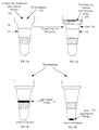
- reaction vessels (10, 20) contain an upper region (10a, 20a), one middle area (10b, 20b) and a lower area (10c, 20c), with a compact porous matrix (12, 22) over the middle area (10b 20b) and the upper (10a, 20a) or lower (10c, 20c) areas a space without a matrix include.
- a liquid in the reaction vessel (14, 24) e.g. a buffer or reagent solution, the Liquid level is above the top of the matrix located.
- the reaction vessel (20) shown in Fig. 1b contains also in the upper area (20a) an extension (26), e.g. in the form of a funnel.
- Microcentrifugation tubes are preferably used as reaction vessels with a volume of 50 ul to 2 ml, in particular from 50 ⁇ l to 1 ml.
- a microcentrifugation tube (20) with extension (26) is the liquid level preferably before adding the agglutination reagent to the sample below the extension (26), so that when pipetting the Sample and agglutination reagent form an air bubble that can be an immediate contact of the pipetted Prevents liquids with the matrix.
- the reaction tube can each according to the embodiment using different methods with the matrix equipped and filled with reagent (buffer or antiserum).
- reagent buffer or antiserum
- the following procedure is recommended: From a commercially available Glass frit becomes a piece in the opening the appropriate shape is removed and placed in the capillary. This can be connected to the matrix by simple heating become. The filling is done by simple capillary action, by immersing the capillary in the reagent. This will the liquid is drawn in and the air is pushed out from below. The process can be carried out at any time depending on the desired fill level be canceled.
- the reaction tube shown in Fig. 1a is obtained by simply melting. Possibly, if longer storage is planned the upper opening of the capillary can also be melted shut. For Application, the upper part is simply broken off, if necessary with the help of a break groove.
- the manual described here Manufacturing processes can of course be used today Available tools very cost-effectively by machine in large numbers.
- the surface of the matrix can be used for certain embodiments of the method according to the invention also antigens or Antibodies are immobilized.
- Fig. 2 shows a reaction scheme for the detection of a carrier-bound Antigen in a sample liquid, e.g. the determination of a blood group characteristic in a patient sample Use of the reaction vessel shown in Fig. 1a and Antibodies as an agglutination reagent.
- a reaction vessel (30) with a compact Matrix in which there is an antibody against the one to be determined Solution (32) containing analytes is a sample liquid (34) e.g. Blood, given a carrier-bound analyte, e.g. one bound to the surface of erythrocytes Blood group feature, contains (Fig. 2a). After centrifugation is found in a strongly positive agglutination reaction (Fig. 2b) a band of agglutination products (36) on the Top of the matrix. If only a weakly positive reaction takes place, one finds the agglutination product (38) within the compact matrix (cf. FIG. 2c). With a negative Reaction, i.e.
- Fig. 3 shows a reaction scheme for the detection of in the Sample liquid existing specific antibodies below Use of a carrier-bound antigen as an agglutination reagent in a reaction vessel according to FIG. 1b.
- a suitable liquid e.g. a buffer solution or a second antibody (Coombs test)
- a carrier-bound antigen e.g. one on the surface of latex particles fixed antigen, (56).
- a sample liquid and carrier-bound antigen e.g. one on the surface of latex particles fixed antigen
- the sample liquid and carrier-bound antigen one through an air bubble (58) from the Liquid (52) result in separate mixture (60) (see Fig. 3b).
- the non-agglutivated one Agglutination reagent i.e. the carrier-bound antigen (64), which penetrates the channels of the matrix and at the bottom of the reaction vessel sedimented (see Fig. 3d).
- Process microreaction vessels used on a card or any number of disks arranged side by side can be.
- a test card can be different Species.
- tubes on a card or disc is glued or the tubes can be integrated into the card or disc.
- reaction vessels can already be an agglutination reagent included and sealed with a welded film his. Allow test made in this way easy handling and can be automated Analysis methods are used.
- the sample can be added into the individual tubes, the sample treatment and the Evaluation controlled by electronic data processing become.
- the compact matrix also allows a surprising process, which agglutination reactions are particularly easy and can be automated cost-effectively.
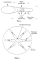
- You can do this Reaction vessels (70) according to FIG. 4 are used.
- Such Reaction vessels contain a matrix with channels (72) as well a room without matrix (74) and are with a suitable one Liquid (76), e.g. Buffer or antiserum until about upper matrix end filled.
- the reaction vessels an extension (78), e.g. in the form of a bulge.
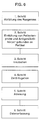
- the Reaction tubes are preferably horizontal on a disc (Fig. 5) attached or integrated in any number. The as a result, the simplicity of the reaction steps has not yet been achieved is explained in the flow diagram according to FIG.
- the first Step becomes what is needed for the respective reaction Reagent, be it buffer or antiserum, in the bulge of the Pipetted tube.
- the liquid is removed by centrifugation transferred to the lower part of the tube, where at the same time the air in the tube is pressed out becomes.
- This first step can either be done immediately before actual analysis or previously in an industrial manufacturing process respectively. In the latter case, the reaction vessels of course be tightly closed, for example by welding with a foil.
- the 2nd step the patient sample and in reactions according to FIG. 3 antigen bound to particles in the bulge.
- antigens and antibodies react in the incubation phase. Of course, this step can be used for reactions according to FIG. 2 can be skipped.
- reaction patterns according to FIGS. 2b, 2c, 2d form. These reaction patterns are automatically read in step 5 (e.g. by a scanner) and interpreted in a computer program.
- step 5 e.g. by a scanner
- step 6th step the data for acquisition transferred, with each result visually verified for safety can be.
- the reaction vessel and the agglutination reagent can be in physically separate form.
- the compact matrix is preferred inserted into the reaction vessel in such a way that during centrifugation no shifts can take place.
- the matrix is expediently in direct contact with the Inside of the reaction vessel, so that during centrifugation no components of the reaction mixture between the inner wall of the reaction vessel and matrix can pass through.
- the matrix does not extend over the entire Area of the reaction vessel, but only over a middle Area.
- the reagent kit contains several tubes that are arranged together on a card or disc.
- the on can be located on a card or disc to detect the same analyte or to detect different ones Analytes can be provided.
- the volume of the reaction vessels is preferably from 50 ⁇ l to 2 ml.
- Yet another object of the present invention is a reaction vessel that contains a compact porous matrix, wherein the matrix is arranged such that during centrifugation no displacement of the matrix within the vessel takes place.
- the reaction vessel is preferably at least partially optically transparent, so that a simple Determination of the occurrence or absence of an agglutination reaction is possible.
- the reaction vessels are made as previously described and filled with an antibody solution. Only in In this case, instead of Anti-A, a Coombs serum (Antihuman IgG) filled. Suitable filled vessels that one Contain funnel (Fig. 1b) or a bulge (Fig. 4) are with 50 ul of a 0.8% erythrocyte suspension (DiaMed test cells) filled with 25 ⁇ l patient serum mixed. In the funnel (Fig. 1b) or the bulge (Fig. 4) the mixture of test cells and serum 15 min. incubated at 37 ° C. After centrifugation, the reaction patterns are same as in the previous examples. With a weak antibody reaction, it forms Reaction pattern according to FIG. 2c.
Landscapes
- Health & Medical Sciences (AREA)
- Chemical & Material Sciences (AREA)
- Immunology (AREA)
- Life Sciences & Earth Sciences (AREA)
- Hematology (AREA)
- Engineering & Computer Science (AREA)
- Analytical Chemistry (AREA)
- General Health & Medical Sciences (AREA)
- Urology & Nephrology (AREA)
- Molecular Biology (AREA)
- Biomedical Technology (AREA)
- Cell Biology (AREA)
- Physics & Mathematics (AREA)
- Microbiology (AREA)
- Chemical Kinetics & Catalysis (AREA)
- Clinical Laboratory Science (AREA)
- Food Science & Technology (AREA)
- Medicinal Chemistry (AREA)
- Biotechnology (AREA)
- Biochemistry (AREA)
- General Physics & Mathematics (AREA)
- Pathology (AREA)
- Investigating Or Analysing Biological Materials (AREA)
- Automatic Analysis And Handling Materials Therefor (AREA)
- Medicines Containing Antibodies Or Antigens For Use As Internal Diagnostic Agents (AREA)
- Medicines Containing Material From Animals Or Micro-Organisms (AREA)
Description
| Kennzeichnung | Kennzeichnung ISO 4793 | Nennwerte der Porenweite µm |
| G0 | P250 | 160-250 |
| G1 | P160 | 100-160 |
| G2 | P100 | 40-100 |
| G3 | P 40 | 16-40 |
| G4 | P 16 | 10-16 |
| G5 | P 1,6 | 1,0-1,6 |
- Fig. 1a
- eine erste Ausführungsform eines Reaktionsgefäßes im Querschnitt mit kompakter Matrix und Kanälen, beispielsweise eine im Handel erhältliche Glaskapillare, die eine integrierte Matrix enthält;
- Fig. 1b
- eine zweite Ausführungsform eines Reaktionsgefäßes im Querschnitt mit kompakter Matrix und Kanälen, beispielsweise Mikroreaktionsgefäße, wie sie im Handel z.B. von DiaMed und Ortho erhältlich sind und die eine integrierte Matrix enthalten;
- Fig. 2
- die Reaktion eines trägergebundenen Antigens in einer Probeflüssigkeit mit einem Agglutinationsreagenz in einem Reaktionsgefäß gemäß Fig. 1a;
- Fig. 3
- die Reaktion eines trägergebundenen Agglutinationsreagenz mit in einer Probeflüssigkeit vorhandenen spezifischen Antikörpern in einem Reaktionsgefäß gemäß Fig. 1b;
- Fig. 4
- eine dritte Ausführungsform eines Reaktionsgefäßes in der Ansicht von oben, wobei das Röhrchen für Testausführungen in horizontaler Lage konzipiert ist, durch die Verwendung einer kompakten Matrix kann sich die Oberfläche der Matrix nicht verformen;
- Fig. 5
- eine mögliche Anordnung der Reagenzgefäße gemäß Fig. 4 auf einer runden Scheibe;
- Fig. 6
- ein Fließdiagramm, mit dem die Bestimmung von Analyten unter Verwendung der Anordnung gemäß Fig. 5 einfach automatisiert werden kann.
Claims (23)
- Verfahren zum Nachweis eines Analyten in einer Probeflüssigkeit durch Agglutination, wobei man die Probeflüssigkeit mit einem Agglutinationsreagenz in Kontakt bringt und eine Reaktion zwischen dem Analyten und dem Agglutinationsreagenz bestimmt,
dadurch gekennzeichnet, daß man ein Reaktionsgefäß verwendet, das eine einzige kompakte poröse Matrix enthält und das nach Einwirkung von Gravitationskräften eine qualitative oder semiquantitative Bestimmung der Agglutinationsreaktion erlaubt. - Verfahren nach Anspruch 1,
dadurch gekennzeichnet, daß man eine kompakte Matrix verwendet, die Kanäle mit definiertem Durchmesser aufweist. - Verfahren nach Anspruch 1 oder 2,
dadurch gekennzeichnet, daß man eine Matrix auf Basis von Glas oder Kunststoff verwendet. - Verfahren nach Anspruch 3,
dadurch gekennzeichnet, daß man eine oberflächenmodifizierte Glasmatrix verwendet. - Verfahren nach Anspruch 3 oder 4,
dadurch gekennzeichnet, daß man eine silanisierte Glasmatrix verwendet. - Verfahren nach einem der Ansprüche 1-5,
dadurch gekennzeichnet, daß man die Porengröße der Matrix so auswählt, so daß nach Einwirkung von Gravitationskräften(a) bei einer starken Agglutination das Reaktionsprodukt aus dem zu bestimmenden Analyten und dem Agglutinationsreagenz im wesentlichen nicht in die kompakte Matrix eindringen kann,(b) bei einer schwachen Agglutination das Reaktionsprodukt in die kompakte Matrix eindringt, sie aber nicht vollständig durchdringen kann und(c) beim Fehlen einer Agglutination die im Reaktionsgefäß enthaltenen Komponenten die kompakte Matrix im wesentlichen vollständig durchdringen können. - Verfahren nach einem der Ansprüche 1-6,
dadurch gekennzeichnet, daß man zum Nachweis eines freien Antikörpers ein trägergebundenes Antigen als Agglutinationsreagenz verwendet. - Verfahren nach einem der Ansprüche 1-6,
dadurch gekennzeichnet, daß man zum Nachweis eines trägergebundenen Antigens einen freien Antikörper oder ein Fragment davon als Agglutinationsreagenz verwendet. - Verfahren nach einem der Ansprüche 1-6,
dadurch gekennzeichnet, daß man zum Nachweis eines freien Antigens einen trägergebundenen Antikörper bzw. ein trägergebundenes Antikörperfragment verwendet. - Verfahren nach einem der Ansprüche 1-9,
dadurch gekennzeichnet, daß Agglutinationsreagenz und Probeflüssigkeit vorgemischt werden, bevor sie mit der Matrix in Kontakt gebracht werden. - Verfahren nach einem der Ansprüche 1-10,
dadurch gekennzeichnet, daß man ein Reaktionsgefäß (10, 20) mit einem oberen Bereich (10a, 20a), einem mittleren Bereich (10b, 20b) und einem unteren Bereich (10c, 20c) verwendet, wobei sich die Matrix (12, 22) über den mittleren Bereich (10b, 20b) erstreckt und die oberen (10a, 20a) bzw. unteren (10c, 20c) Bereiche einen Raum ohne Matrix umfassen. - Verfahren nach Anspruch 11,
dadurch gekennzeichnet, daß der obere Bereich (20a) des Reaktionsgefäßes (20) eine Erweiterung (26, 78) enthält. - Verfahren nach Anspruch 12,
dadurch gekennzeichnet, daß die Erweiterung in Form eines Trichters oder einer Ausbuchtung ist. - Verfahren nach einem der Ansprüche 1-13,
dadurch gekennzeichnet, daß man als Reaktionsgefäße Mikrozentrifugationsröhrchen mit einem Volumen von 50 µl bis 2 ml verwendet. - Reagenzienkit zum Nachweis eines Analyten in einer Probeflüssigkeit durch Agglutination, umfassend(a) ein Reaktionsgefäß, das eine einzige kompakte poröse Matrix enthält, und(b) ein zur Bildung von Agglutinationskomplexen mit dem Analyten fähiges Agglutinationsreagenz.
- Reagenzienkit nach Anspruch 15,
dadurch gekennzeichnet, daß das Reaktionsgefäß (10, 20) einen oberen Bereich (10a, 20a), einen mittleren Bereich (10b, 20b) und einen unteren Bereich (10c, 20c) umfaßt, wobei sich die Matrix (12, 22) nur über den mittleren Bereich (10b, 20b) erstreckt. - Reagenzienkit nach Anspruch 15 oder 16,
dadurch gekennzeichnet, daß mehrere Reaktionsgefäße zusammen auf einer Karte oder Scheibe angeordnet sind. - Reagenzienkit nach einem der Ansprüche 15-16,
dadurch gekennzeichnet, daß das Reaktionsgefäß ein Volumen von 50 µl bis 2 ml aufweist. - Reaktionsgefäß, das eine einzige kompakte poröse Matrix enthält, wobei die Matrix derart angeordnet ist, daß bei Zentrifugation keine Verschiebung der Matrix innerhalb des Gefäßes stattfindet und daß vorzugsweise keine Flüssigkeit zwischen Gefäßinnenwand und Matrix durchtreten kann.
- Reaktionsgefäß nach Anspruch 19,
dadurch gekennzeichnet, daß es einen oberen Bereich (10a, 20a), einen mittleren Bereich (10b, 20b) und einen unteren Bereich (10c, 20c) umfaßt, wobei sich die Matrix (12, 22) nur über den mittleren Bereich (10b, 20b) erstreckt. - Reaktionsgefäß nach Anspruch 19 oder 20,
dadurch gekennzeichnet, daß der obere Bereich (20a) eine Erweiterung (26, 78), insbesondere in Form eines Trichters oder einer Ausbuchtung umfaßt. - Reaktionsgefäß nach einem der Ansprüche 19-21,
dadurch gekennzeichnet, daß es ein Volumen von 50 µl bis 2 ml aufweist. - Anordnung von mehreren Reaktionsgefäßen zusammen auf einer Karte oder Scheibe,
dadurch gekennzeichnet, daß die Reaktionsgefäße eine einzige kompakte poröse Matrix enthalten, wobei die Matrix derart angeordnet ist, daß bei Zentrifugation keine Verschiebung der Matrix innerhalb des Gefäßes stattfindet und daß vorzugsweise keine Flüssigkeit zwischen Gefäßinnenwand und Matrix durchtreten kann.
Priority Applications (8)
| Application Number | Priority Date | Filing Date | Title |
|---|---|---|---|
| ES96104283T ES2168402T3 (es) | 1996-03-18 | 1996-03-18 | Inmunoanalisis en particulas con una matriz compacta. |
| AT96104283T ATE210829T1 (de) | 1996-03-18 | 1996-03-18 | Partikel-immunoassay mit kompakter matrix |
| DE59608443T DE59608443D1 (de) | 1996-03-18 | 1996-03-18 | Partikel-Immunoassay mit kompakter Matrix |
| DK96104283T DK0797097T3 (da) | 1996-03-18 | 1996-03-18 | Partikel-immunoassay med kompakt matrix |
| PT96104283T PT797097E (pt) | 1996-03-18 | 1996-03-18 | Ensaio imunologico de particulas com matriz compacta |
| EP96104283A EP0797097B1 (de) | 1996-03-18 | 1996-03-18 | Partikel-Immunoassay mit kompakter Matrix |
| US08/822,158 US5869347A (en) | 1996-03-18 | 1997-03-17 | Particle immunoassay using a compact matrix |
| JP9064277A JPH102900A (ja) | 1996-03-18 | 1997-03-18 | サンプル液体中の分析物を検出する方法、試薬キット及び反応容器 |
Applications Claiming Priority (1)
| Application Number | Priority Date | Filing Date | Title |
|---|---|---|---|
| EP96104283A EP0797097B1 (de) | 1996-03-18 | 1996-03-18 | Partikel-Immunoassay mit kompakter Matrix |
Publications (2)
| Publication Number | Publication Date |
|---|---|
| EP0797097A1 EP0797097A1 (de) | 1997-09-24 |
| EP0797097B1 true EP0797097B1 (de) | 2001-12-12 |
Family
ID=8222571
Family Applications (1)
| Application Number | Title | Priority Date | Filing Date |
|---|---|---|---|
| EP96104283A Expired - Lifetime EP0797097B1 (de) | 1996-03-18 | 1996-03-18 | Partikel-Immunoassay mit kompakter Matrix |
Country Status (8)
| Country | Link |
|---|---|
| US (1) | US5869347A (de) |
| EP (1) | EP0797097B1 (de) |
| JP (1) | JPH102900A (de) |
| AT (1) | ATE210829T1 (de) |
| DE (1) | DE59608443D1 (de) |
| DK (1) | DK0797097T3 (de) |
| ES (1) | ES2168402T3 (de) |
| PT (1) | PT797097E (de) |
Cited By (1)
| Publication number | Priority date | Publication date | Assignee | Title |
|---|---|---|---|---|
| EP3326718A1 (de) * | 2013-10-09 | 2018-05-30 | Yantai AusBio Laboratories Co., Ltd. | Mikroplatte zur bestimmung der produkte von agglutinationsreaktionen |
Families Citing this family (13)
| Publication number | Priority date | Publication date | Assignee | Title |
|---|---|---|---|---|
| JP2003107091A (ja) * | 2001-09-28 | 2003-04-09 | Olympus Optical Co Ltd | 生物学的検査のための分離体および検査方法 |
| DE102004005193B4 (de) * | 2004-02-02 | 2006-08-24 | Medion Diagnostics Gmbh | Vorrichtung zur Separation einzelner Partikel von Partikel-Agglutinationen |
| JP2005257337A (ja) * | 2004-03-09 | 2005-09-22 | Brother Ind Ltd | 検査対象受体、検査装置、及び検査方法 |
| JP5008899B2 (ja) | 2006-06-05 | 2012-08-22 | ベックマン コールター, インコーポレイテッド | 粒子凝集判定用容器 |
| JP2008224318A (ja) * | 2007-03-09 | 2008-09-25 | Olympus Corp | 多層型凝集判定容器 |
| JP2008224317A (ja) * | 2007-03-09 | 2008-09-25 | Olympus Corp | 凝集判定装置 |
| WO2010072271A1 (en) * | 2008-12-23 | 2010-07-01 | Symbion Medical Systems Sarl | Device and analyzing system for conducting agglutination assays |
| PT2372366T (pt) * | 2010-03-30 | 2019-10-24 | Symbion Medical Systems Sarl | Estação de análise com sistema de incubação. |
| CN102608336B (zh) * | 2011-01-19 | 2014-12-24 | 刘大基 | 一次性输血交叉配血实验组合器 |
| EP2500095A1 (de) * | 2011-03-15 | 2012-09-19 | Siemens Healthcare Diagnostics Products GmbH | Vorrichtungen und Verfahren zur Bestimmung der Plättchenfunktion in einem Zentrifugalanalyzer |
| JPWO2014203693A1 (ja) * | 2013-06-19 | 2017-02-23 | オリンパス株式会社 | 光学計測用容器 |
| CA3168312A1 (en) | 2020-03-09 | 2021-09-16 | Jesse Daniel Faller | Matrix and associated sample or mixing cup used for removing components of a liquid sample |
| JP7679396B2 (ja) | 2020-03-09 | 2025-05-19 | アイデックス ラボラトリーズ インコーポレイテッド | 液体サンプルの干渉成分を化学試薬検査スライドへの適用前に除去するための方法 |
Family Cites Families (7)
| Publication number | Priority date | Publication date | Assignee | Title |
|---|---|---|---|---|
| JPS5933228B2 (ja) * | 1978-12-25 | 1984-08-14 | 武田薬品工業株式会社 | 妊娠診断反応用被検液の前処理方法ならびに前処理剤 |
| DE3342627A1 (de) * | 1983-11-25 | 1985-06-05 | Boehringer Mannheim Gmbh, 6800 Mannheim | Immunchemischer schnelltest |
| FR2577321B1 (fr) * | 1985-02-08 | 1989-04-28 | Lapierre Yves | Dispositif et procede de mise en evidence d'agglutinats erythrocytaires |
| US5073344A (en) * | 1987-07-17 | 1991-12-17 | Porex Technologies Corp. | Diagnostic system employing a unitary substrate to immobilize microspheres |
| JPH087215B2 (ja) * | 1987-08-24 | 1996-01-29 | シュティフツング・フュア・ディアグノスティッシュ・フォルシュンク | 抗原および/又は抗体の検出方法および検出用の試験キット |
| ATE153138T1 (de) * | 1990-09-26 | 1997-05-15 | Akers Lab Inc | Verbessertes bestimmungsverfahren für liganden |
| GR1002306B (el) * | 1990-11-09 | 1996-05-08 | Ortho Diagnostic Systems Inc. | Αναλυση και διαταξη συγκολλησεως στηλης. |
-
1996
- 1996-03-18 PT PT96104283T patent/PT797097E/pt unknown
- 1996-03-18 DE DE59608443T patent/DE59608443D1/de not_active Expired - Lifetime
- 1996-03-18 ES ES96104283T patent/ES2168402T3/es not_active Expired - Lifetime
- 1996-03-18 AT AT96104283T patent/ATE210829T1/de active
- 1996-03-18 DK DK96104283T patent/DK0797097T3/da active
- 1996-03-18 EP EP96104283A patent/EP0797097B1/de not_active Expired - Lifetime
-
1997
- 1997-03-17 US US08/822,158 patent/US5869347A/en not_active Expired - Lifetime
- 1997-03-18 JP JP9064277A patent/JPH102900A/ja active Pending
Cited By (1)
| Publication number | Priority date | Publication date | Assignee | Title |
|---|---|---|---|---|
| EP3326718A1 (de) * | 2013-10-09 | 2018-05-30 | Yantai AusBio Laboratories Co., Ltd. | Mikroplatte zur bestimmung der produkte von agglutinationsreaktionen |
Also Published As
| Publication number | Publication date |
|---|---|
| DK0797097T3 (da) | 2002-04-15 |
| ATE210829T1 (de) | 2001-12-15 |
| JPH102900A (ja) | 1998-01-06 |
| PT797097E (pt) | 2002-06-28 |
| EP0797097A1 (de) | 1997-09-24 |
| DE59608443D1 (de) | 2002-01-24 |
| ES2168402T3 (es) | 2002-06-16 |
| US5869347A (en) | 1999-02-09 |
Similar Documents
| Publication | Publication Date | Title |
|---|---|---|
| EP0305337B1 (de) | Verfahren zum Nachweis von Antigenen und/oder Antikörpern sowie Testausrüstung zur Durchführung des Verfahrens | |
| DE3882040T2 (de) | Verfahren und vorrichtungen zur durchführung von untersuchungen. | |
| EP0073513B2 (de) | Verfahren zur Durchführung analytischer Bestimmungen und hierfür geeignetes Mittel | |
| DE3880531T2 (de) | Integriertes immunoassayelement. | |
| DE69016813T2 (de) | Verfahren und Vorrichtung zur Trennung von Plasma oder von Serum aus Blut. | |
| DE68911395T2 (de) | Vorrichtung zum Transportieren von Flüssigkeiten und Vorrichtung zur diagnostischen Analyse. | |
| DE2912173C2 (de) | Reaktor/Separator-Vorrichtung | |
| DE69226257T2 (de) | Vorrichtung zur antigen-bestimmung in kapillär-blut | |
| EP0797097B1 (de) | Partikel-Immunoassay mit kompakter Matrix | |
| DE69018970T2 (de) | Prüfung von flüssigkeiten. | |
| DE3586983T2 (de) | Verfahren und vorrichtung fuer immunotest. | |
| DE69016740T2 (de) | Analytisches element. | |
| DE69229478T2 (de) | Vorrichtung und verfahren zur dosierung von flüssigkeitsproben | |
| DE69814052T2 (de) | Automatische immunoassay kassette | |
| DE69106156T2 (de) | Nichtinstrumentierter Cholesterintest. | |
| DE69122036T2 (de) | Säulenagglutinationsassay und Vorrichtung | |
| DE3618101C2 (de) | ||
| DE69414650T2 (de) | Agglutination Reaktion- und Trennungsgefäss | |
| DE68909568T2 (de) | Analytisches Testgerät. | |
| DE69503558T2 (de) | Vorrichtung und Verfahren zur immunologischen Analyse | |
| DE69021529T2 (de) | Reaktionsgefäss. | |
| EP1495799A2 (de) | Vorrichtung zum Handhaben von begrenzten Flüssigkeitsmengen | |
| DD202072A5 (de) | Verfahren zur durchfuehrung analytischer bestimmungen und hierfuer geeignetes rotoreinsatzelement | |
| CH637219A5 (de) | Photometrisches untersuchungsverfahren zur immunbestimmung und enzymreaktion. | |
| DE69023476T2 (de) | Mehrschicht-Testvorrichtung zur Bestimmung von Substanzen in Flüssigkeiten. |
Legal Events
| Date | Code | Title | Description |
|---|---|---|---|
| PUAI | Public reference made under article 153(3) epc to a published international application that has entered the european phase |
Free format text: ORIGINAL CODE: 0009012 |
|
| AK | Designated contracting states |
Kind code of ref document: A1 Designated state(s): AT BE CH DE DK ES FI FR GB GR IE IT LI NL PT SE |
|
| AX | Request for extension of the european patent |
Free format text: AL;LT;LV;SI |
|
| RBV | Designated contracting states (corrected) |
Designated state(s): AT BE CH DE DK ES FI FR GB GR IE IT LI NL PT SE |
|
| 17P | Request for examination filed |
Effective date: 19980203 |
|
| 17Q | First examination report despatched |
Effective date: 20000404 |
|
| GRAG | Despatch of communication of intention to grant |
Free format text: ORIGINAL CODE: EPIDOS AGRA |
|
| GRAG | Despatch of communication of intention to grant |
Free format text: ORIGINAL CODE: EPIDOS AGRA |
|
| GRAH | Despatch of communication of intention to grant a patent |
Free format text: ORIGINAL CODE: EPIDOS IGRA |
|
| GRAH | Despatch of communication of intention to grant a patent |
Free format text: ORIGINAL CODE: EPIDOS IGRA |
|
| GRAH | Despatch of communication of intention to grant a patent |
Free format text: ORIGINAL CODE: EPIDOS IGRA |
|
| GRAH | Despatch of communication of intention to grant a patent |
Free format text: ORIGINAL CODE: EPIDOS IGRA |
|
| GRAA | (expected) grant |
Free format text: ORIGINAL CODE: 0009210 |
|
| AK | Designated contracting states |
Kind code of ref document: B1 Designated state(s): AT BE CH DE DK ES FI FR GB GR IE IT LI NL PT SE |
|
| PG25 | Lapsed in a contracting state [announced via postgrant information from national office to epo] |
Ref country code: GR Free format text: LAPSE BECAUSE OF FAILURE TO SUBMIT A TRANSLATION OF THE DESCRIPTION OR TO PAY THE FEE WITHIN THE PRESCRIBED TIME-LIMIT Effective date: 20011212 |
|
| REF | Corresponds to: |
Ref document number: 210829 Country of ref document: AT Date of ref document: 20011215 Kind code of ref document: T |
|
| REG | Reference to a national code |
Ref country code: CH Ref legal event code: NV Representative=s name: A. BRAUN, BRAUN, HERITIER, ESCHMANN AG PATENTANWAE Ref country code: CH Ref legal event code: EP |
|
| REG | Reference to a national code |
Ref country code: GB Ref legal event code: IF02 |
|
| GBT | Gb: translation of ep patent filed (gb section 77(6)(a)/1977) |
Effective date: 20011212 |
|
| REG | Reference to a national code |
Ref country code: IE Ref legal event code: FG4D Free format text: GERMAN |
|
| REF | Corresponds to: |
Ref document number: 59608443 Country of ref document: DE Date of ref document: 20020124 |
|
| REG | Reference to a national code |
Ref country code: DK Ref legal event code: T3 |
|
| ET | Fr: translation filed | ||
| REG | Reference to a national code |
Ref country code: GR Ref legal event code: EP Ref document number: 20020400285 Country of ref document: GR |
|
| REG | Reference to a national code |
Ref country code: ES Ref legal event code: FG2A Ref document number: 2168402 Country of ref document: ES Kind code of ref document: T3 |
|
| REG | Reference to a national code |
Ref country code: PT Ref legal event code: SC4A Free format text: AVAILABILITY OF NATIONAL TRANSLATION Effective date: 20020312 |
|
| PLBE | No opposition filed within time limit |
Free format text: ORIGINAL CODE: 0009261 |
|
| STAA | Information on the status of an ep patent application or granted ep patent |
Free format text: STATUS: NO OPPOSITION FILED WITHIN TIME LIMIT |
|
| 26N | No opposition filed | ||
| REG | Reference to a national code |
Ref country code: CH Ref legal event code: PFA Owner name: STIFTUNG FUER DIAGNOSTISCHE FORSCHUNG Free format text: STIFTUNG FUER DIAGNOSTISCHE FORSCHUNG#PRAZ-ROND#CH-1785 CRESSIER SUR MORAT (CH) -TRANSFER TO- STIFTUNG FUER DIAGNOSTISCHE FORSCHUNG#PRAZ-ROND#CH-1785 CRESSIER SUR MORAT (CH) |
|
| REG | Reference to a national code |
Ref country code: CH Ref legal event code: PLI Owner name: DIAMED AG Free format text: STIFTUNG FUER DIAGNOSTISCHE FORSCHUNG#PRAZ-ROND#CH-1785 CRESSIER SUR MORAT (CH) -TRANSFER TO- DIAMED AG#PRAZ-ROND#1785 CRESSIER-SUR-MORAT (CH) |
|
| REG | Reference to a national code |
Ref country code: GB Ref legal event code: 732E Free format text: REGISTERED BETWEEN 20090305 AND 20090311 |
|
| REG | Reference to a national code |
Ref country code: FR Ref legal event code: CL |
|
| NLUE | Nl: licence registered with regard to european patents |
Effective date: 20090303 |
|
| NLUE | Nl: licence registered with regard to european patents |
Effective date: 20090327 |
|
| REG | Reference to a national code |
Ref country code: ES Ref legal event code: GD2A Effective date: 20090907 |
|
| REG | Reference to a national code |
Ref country code: ES Ref legal event code: GD2A Effective date: 20100209 |
|
| REG | Reference to a national code |
Ref country code: ES Ref legal event code: GD2A Effective date: 20100209 |
|
| PGFP | Annual fee paid to national office [announced via postgrant information from national office to epo] |
Ref country code: CH Payment date: 20120326 Year of fee payment: 17 Ref country code: IE Payment date: 20120322 Year of fee payment: 17 Ref country code: FR Payment date: 20120403 Year of fee payment: 17 |
|
| PGFP | Annual fee paid to national office [announced via postgrant information from national office to epo] |
Ref country code: DE Payment date: 20120315 Year of fee payment: 17 Ref country code: PT Payment date: 20120316 Year of fee payment: 17 |
|
| PGFP | Annual fee paid to national office [announced via postgrant information from national office to epo] |
Ref country code: SE Payment date: 20120322 Year of fee payment: 17 Ref country code: FI Payment date: 20120323 Year of fee payment: 17 Ref country code: BE Payment date: 20120329 Year of fee payment: 17 Ref country code: DK Payment date: 20120322 Year of fee payment: 17 Ref country code: GR Payment date: 20120329 Year of fee payment: 17 Ref country code: GB Payment date: 20120322 Year of fee payment: 17 |
|
| PGFP | Annual fee paid to national office [announced via postgrant information from national office to epo] |
Ref country code: NL Payment date: 20120327 Year of fee payment: 17 |
|
| PGFP | Annual fee paid to national office [announced via postgrant information from national office to epo] |
Ref country code: IT Payment date: 20120329 Year of fee payment: 17 |
|
| PGFP | Annual fee paid to national office [announced via postgrant information from national office to epo] |
Ref country code: AT Payment date: 20120323 Year of fee payment: 17 |
|
| PGFP | Annual fee paid to national office [announced via postgrant information from national office to epo] |
Ref country code: ES Payment date: 20120327 Year of fee payment: 17 |
|
| REG | Reference to a national code |
Ref country code: PT Ref legal event code: MM4A Free format text: LAPSE DUE TO NON-PAYMENT OF FEES Effective date: 20130918 |
|
| BERE | Be: lapsed |
Owner name: *STIFTUNG FUR DIAGNOSTISCHE FORSCHUNG Effective date: 20130331 |
|
| REG | Reference to a national code |
Ref country code: NL Ref legal event code: V1 Effective date: 20131001 |
|
| REG | Reference to a national code |
Ref country code: DK Ref legal event code: EBP Effective date: 20130331 |
|
| REG | Reference to a national code |
Ref country code: SE Ref legal event code: EUG |
|
| PG25 | Lapsed in a contracting state [announced via postgrant information from national office to epo] |
Ref country code: SE Free format text: LAPSE BECAUSE OF NON-PAYMENT OF DUE FEES Effective date: 20130319 Ref country code: FI Free format text: LAPSE BECAUSE OF NON-PAYMENT OF DUE FEES Effective date: 20130318 Ref country code: PT Free format text: LAPSE BECAUSE OF NON-PAYMENT OF DUE FEES Effective date: 20130918 |
|
| REG | Reference to a national code |
Ref country code: CH Ref legal event code: PL |
|
| REG | Reference to a national code |
Ref country code: AT Ref legal event code: MM01 Ref document number: 210829 Country of ref document: AT Kind code of ref document: T Effective date: 20130318 |
|
| REG | Reference to a national code |
Ref country code: GR Ref legal event code: ML Ref document number: 20020400285 Country of ref document: GR Effective date: 20131002 |
|
| GBPC | Gb: european patent ceased through non-payment of renewal fee |
Effective date: 20130318 |
|
| REG | Reference to a national code |
Ref country code: FR Ref legal event code: ST Effective date: 20131129 |
|
| REG | Reference to a national code |
Ref country code: IE Ref legal event code: MM4A |
|
| REG | Reference to a national code |
Ref country code: DE Ref legal event code: R119 Ref document number: 59608443 Country of ref document: DE Effective date: 20131001 |
|
| PG25 | Lapsed in a contracting state [announced via postgrant information from national office to epo] |
Ref country code: DE Free format text: LAPSE BECAUSE OF NON-PAYMENT OF DUE FEES Effective date: 20131001 Ref country code: AT Free format text: LAPSE BECAUSE OF NON-PAYMENT OF DUE FEES Effective date: 20130318 Ref country code: LI Free format text: LAPSE BECAUSE OF NON-PAYMENT OF DUE FEES Effective date: 20130331 Ref country code: CH Free format text: LAPSE BECAUSE OF NON-PAYMENT OF DUE FEES Effective date: 20130331 Ref country code: FR Free format text: LAPSE BECAUSE OF NON-PAYMENT OF DUE FEES Effective date: 20130402 Ref country code: GB Free format text: LAPSE BECAUSE OF NON-PAYMENT OF DUE FEES Effective date: 20130318 Ref country code: IE Free format text: LAPSE BECAUSE OF NON-PAYMENT OF DUE FEES Effective date: 20130318 Ref country code: BE Free format text: LAPSE BECAUSE OF NON-PAYMENT OF DUE FEES Effective date: 20130331 |
|
| PG25 | Lapsed in a contracting state [announced via postgrant information from national office to epo] |
Ref country code: NL Free format text: LAPSE BECAUSE OF NON-PAYMENT OF DUE FEES Effective date: 20131001 Ref country code: IT Free format text: LAPSE BECAUSE OF NON-PAYMENT OF DUE FEES Effective date: 20130318 Ref country code: GR Free format text: LAPSE BECAUSE OF FAILURE TO SUBMIT A TRANSLATION OF THE DESCRIPTION OR TO PAY THE FEE WITHIN THE PRESCRIBED TIME-LIMIT Effective date: 20131002 |
|
| PG25 | Lapsed in a contracting state [announced via postgrant information from national office to epo] |
Ref country code: DK Free format text: LAPSE BECAUSE OF NON-PAYMENT OF DUE FEES Effective date: 20130331 |
|
| REG | Reference to a national code |
Ref country code: ES Ref legal event code: FD2A Effective date: 20140606 |
|
| PG25 | Lapsed in a contracting state [announced via postgrant information from national office to epo] |
Ref country code: ES Free format text: LAPSE BECAUSE OF NON-PAYMENT OF DUE FEES Effective date: 20130319 |