EP0797076B1 - Surveying system - Google Patents
Surveying system Download PDFInfo
- Publication number
- EP0797076B1 EP0797076B1 EP97250082A EP97250082A EP0797076B1 EP 0797076 B1 EP0797076 B1 EP 0797076B1 EP 97250082 A EP97250082 A EP 97250082A EP 97250082 A EP97250082 A EP 97250082A EP 0797076 B1 EP0797076 B1 EP 0797076B1
- Authority
- EP
- European Patent Office
- Prior art keywords
- surveying
- signal light
- direction detecting
- rough
- light
- Prior art date
- Legal status (The legal status is an assumption and is not a legal conclusion. Google has not performed a legal analysis and makes no representation as to the accuracy of the status listed.)
- Expired - Lifetime
Links
Images


Classifications
-
- G—PHYSICS
- G01—MEASURING; TESTING
- G01C—MEASURING DISTANCES, LEVELS OR BEARINGS; SURVEYING; NAVIGATION; GYROSCOPIC INSTRUMENTS; PHOTOGRAMMETRY OR VIDEOGRAMMETRY
- G01C15/00—Surveying instruments or accessories not provided for in groups G01C1/00 - G01C13/00
- G01C15/002—Active optical surveying means
Definitions
- This invention relates to improvements in a surveying system for making a survey by operating a surveying machine by remote control.
- a surveying system for making a survey comprises, for example, a surveying machine which is disposed at a reference point, and a reflecting mirror (e.g., a corner cube) as a collimation target which is disposed at a target point collimated by the surveying machine.
- the surveying machine used for the surveying system is to process a surveyed distance and a surveyed angle electrically.
- some surveying machines include a point setting device in order that an operator at the target point can discern the surveying machine disposed at a reference point.
- the point setting device emits point setting beams of light each of which has a different luminous color depending upon right and left positions (or up, down, right, and left positions), or a middle position, so that a direction in which the surveying machine collimates can be indicated roughly.
- an operator on the side of the reference point operates the surveying machine and searches the reflecting mirror as the collimation target disposed at the target point.
- a survey is made while an operator on the side of the surveying machine is communicating by wireless with an operator on the side of the collimation target, or rough positioning is first made by the point setting beams of light and thereafter a survey is made while the operators are communicating by wireless with each other.
- the automatic surveying machine can be operated by radio or the like from the side of the target point by using the point setting beams of light.
- the target point can be caused to coincide with the collimation target. Therefore, the operator is not necessarily required to be stationed on the side of the surveying machine.
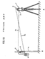
- a surveying system by the use of this automatic surveying machine is shown in Fig. 10.
- reference character 1 denotes a surveying machine
- 2 denotes a telescope portion
- 3 denotes a wireless communications apparatus.
- the surveying machine 1 is laid on a reference point A.
- the surveying machine 1 emits a beam of light P1 which is used for measuring a distance at a target point B.
- a collimation axis of the telescope portion 2 is made coaxial (or parallel) with the distance-measuring light beam P1.
- the surveying machine 1 is capable of measuring a horizontal angle and a vertical angle with a zero position, and has an automatic rotational mechanism by which the rotation in horizontal and vertical directions can be made automatically (with respect to a detailed construction of the automatic rotational mechanism, see Japanese Patent Application Early Laid-Open Publication No. Hei 4-131078, for example).
- the rotation in the horizontal direction means that the rotation is made on the horizontal plane
- the rotation in the vertical direction means that the rotation is made on the vertical plane.
- a pole 4 is stood at a target point B.
- a reflecting mirror 5 is attached to the pole 4 and, in addition, a wireless communications apparatus 6 and a control device 7 having a memorizing function are attached thereto.
- the reflecting mirror 5 disposed at the target point B is made coincident with the collimation axis of the telescope portion 2 of the surveying machine 1, and thereby the distance and the angle from the surveying machine 1 to the target point B can be measured by the surveying machine 1.
- the control device 7 is used for controlling the surveying machine 1 via the wireless communications apparatus 3, 6 and, in addition, for recording and reading the result of measurement made by the surveying machine 1 on the side of the target point B.
- the automatic tracking type of surveying machine enables labor saving in comparison with the aforementioned automatic surveying machine. That is, the collimation target is caused to roughly coincide by, for example, the point setting device, and thereafter the reflecting mirror of the target point is located by the scanning light emitted from the tracking type of surveying machine for collimation.
- the point setting beam of light is used to cause the collimation axis of the telescope portion 2 to coincide with the reflecting mirror 5.
- a surveying system by the use of the tracking type of surveying machine has a great advantage in a case in which a plurality of predetermined target points B are repeatedly measured with the condition that obstructions do not lie between the reference point A and the target points B and that the pole 4 erected at the target point B is moved slowly.
- this system has a disadvantage in a case in which a plurality of target points are marked and in a case in which the pole 4 is moved. The reason is that the reflecting mirror must be automatically tracked.
- the automatic surveying machine will lose sight of the reflecting mirror 5.
- the automatic surveying machine has a reflecting-mirror search mode (a mode of searching for a reflecting-mirror) in which the automatic surveying machine searches a very large range. Accordingly, much time is required to search the reflecting mirror 5.
- the automatic surveying machine is controlled by sending out or receiving an operation starting or stopping signal by means of a wireless wave P2 by the use of the wireless communications apparatus 3, 6, it is difficult to cause the collimation of the telescope portion 2 to coincide with the reflecting mirror 5 when the distance from the reference point A to the target point B is too long to discern the surveying machine 1.
- the frequency and output power of the wireless communications apparatus 3, 6 are required to be varied in every country in the world because each country has its own regulations on the wireless wave P2.
- CH 676 041 A discloses a surveying system comprising a surveying machine to be disposed at a reference point, said surveying machine having a rotation mechanism to be rotated in horizontal and vertical directions and a light source for emitting light pulses.
- Target points reflect the light pulses back to the surveying machine which includes means for roughly determining the position of a target point and then precisely determining this position by evaluating the reflected light pulses.
- An object of the present invention is to provide a surveying system which is capable of directing easily an automatic surveying machine toward a target point even when the automatic surveying machine is in a direction different from the target point beyond the range within which the automatic surveying machine is detectable, and which is capable of causing the collimation axis of a telescope portion of the automatic surveying machine to coincide with the target point without being subject to the regulation in each country to the utmost even when the automatic surveying machine is positioned so far from the target point that the telescope portion cannot be discerned with the naked eye.
- the surveying system for rotating automatically a collimation axis of the telescope portion of a surveying machine in horizontal and vertical directions comprises a machine body and a telescope portion rotatable in horizontal and vertical directions respectively, a signal light projecting device for projecting a signal light from the side of a target point toward said surveying machine; a rough direction detecting device disposed on the side of said machine body for receiving said signal light from said signal light projecting device; a precise-direction detecting device disposed on the machine body or the telescope portion and disposed to direct towards the collimation axis of the telescope portion for receiving said signal light from said signal light projecting device and control means for controlling said collimation axis of the telescope portion to direct toward said signal light projecting device based on a difference between the collimation axis of the telescope portion and the direction of signal light received lights detected by said rough-direction detecting devices, wherein said precise-direction detecting device is for detecting precisely said collimation axis of the telescope portion, and said rough-direction detecting devices
- an orientation of the surveying machine body can be made approximately coincident with a direction of the signal-light projecting device because the beam of signal light is received by the rough-direction detecting means even though the automatic surveying machine is in a direction entirely different from the target point beyond the detectable range of the automatic surveying machine.
- the beam of signal light is received by the precise-direction detecting means so that the orientation of the surveying machine body can be made precisely coincident with the direction of the signal-light projecting device.
- the collimation axis of the telescope portion of the automatic surveying machine can be made coincident with the target point because the rough-direction detecting means and the precise-direction detecting means are provided.
- the surveying system is not subject to the regulation on a wireless operation in each country.
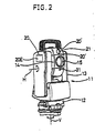
- reference character 11 designates an automatic surveying machine disposed on a tripod.
- the automatic surveying machine 11 is laid at a reference point A.
- the automatic surveying machine 11 includes a base 12, mounting portions 13 constituting a surveying machine body, and a telescope portion 14.
- the mounting portion 13 is rotated around a vertical axis V in a horizontal direction.
- the telescope portion 14 is rotated around a horizontal axis H in a vertical direction.
- These automatic rotational mechanisms are controlled by a CPU 24 (see Figs. 4 and 6) which is disposed inside the mounting portion 13.
- the telescope portion 14 includes a telescope, and reference character 15 in Fig. 2 designates an objective constituting the telescope.
- the surveying machine 11 emits a beam of light P1 used for measuring a distance toward a reflecting mirror 5 (e.g., a corner cube) which is attached to a pole 4 at a target point B.
- the direction in which the beam of distance-measuring light P1 is emitted is correspondent with, or parallel to, the optical axis of the objective 15, that is, the collimation axis of the telescope portion 14.
- the beam of distance-measuring light P1 is reflected by the reflecting mirror 5, and then the surveying machine 11 receives the reflected beam of light and thus measures the distance from the reference point A to the target point B.
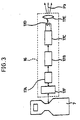
- a signal-light projecting device 16 for projecting a beam of signal light P3 toward the surveying machine 11 is attached to the pole 4.
- the signal-light projecting device 16 consists of a CPU 17A, a modulation circuit 17B, a drive circuit 17C, a luminescent element 17D which is turned on and off by the drive circuit 17C, a light projection lens 17E for condensing a beam of light which is set at need.
- the CPU 17A is controlled by a control device 7 having a memorizing function.
- Reference character 17F designates an interface which makes a connection between the CPU 17A and the control device 7.
- a beam of signal light P3 is emitted radially through the light projection lens 17E.
- the beam of signal light P3 is composed, for example, of pulsed light.
- the rough-direction detecting devices 20 for detecting roughly a direction where the signal-light projecting device 16 is located by receiving the beam of signal light P3, and a precise-direction detecting device 21 for detecting precisely a direction where the signal-light projecting device 16 is located by receiving the beam of signal light P3.
- the rough-direction detecting devices 20 are disposed, for example, on the sides of the right and left mounting portions 13 and on the side of an eyepiece (not shown) of the telescope portion 14, and the precise-direction detecting device 21 is disposed on the side of the objective 15 of the telescope portion 14. As shown in Fig.
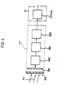
- the rough-direction detecting portion 20 consists, upon the whole, of a light receiving window 20E, a light receiving element 20A, an electric filter circuit 20B, a demodulation circuit 20C, and an A/D conversion circuit 20D.
- the beam of signal light P3 is modulated and emitted from the signal-light projecting device 16, and then the beam of signal light P3 is received by the light receiving element 20A.
- the light receiving element 20A converts photoelectrically the beam of signal light P3, a modulated signal of the photoelectrically-converted signal is then removed by the electric filter circuit 20B, the photoelectrically-converted signal whose modulated signal has been removed is then demodulated by the demodulation circuit 20C and is converted into a digital signal by the A/D conversion circuit 20D, and thereafter is inputted in a CPU 24 of the surveying machine 11.
- a position of the signal-light projecting device 16 is not required to be judged. In other words, all that is required for judgment is whether the beam of signal light P3 is projected or how much the beam of signal light P3 is intensive. As a consequence, an element having a comparatively simple structure can be used as the light receiving element 20A.
- the rough-direction detecting device 20 in the rear of the surveying machine 11 and the rough-direction detecting device 20 in the right-hand part thereof receive the beam of signal light P3 simultaneously
- the difference between the direction in which the surveying machine body is sighted and the direction of the target point at this point of time can be recognized according to the position where the rough-direction detecting device 20 has received the beam of signal light P3.
- the difference enables the surveying machine 11 to be directed substantially to the target point, and thus the intensity of the photoelectrically-converted signal is detected, so that the accuracy of judging what direction the beam of signal light P3 has come from can be still more heightened.
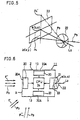
- the precise-direction detecting device 21 receives the beam of signal light P3.
- Fig. 5 is a schematic drawing showing a light receiving portion 21F of the precise-direction detecting device 21.
- reference character 22 designates a condensing lens
- 23 designates a light receiving element.
- the precise-direction detecting device 21 includes the same electric circuit as the rough-direction detecting device 20.
- the beam of signal light P3 is condensed to the light receiving element by the condensing lens 22.
- a CCD, a PSD, a two-pieces divided type element, or a four-pieces divided type element is used as the light receiving element 23.
- the light receiving element 23 detects the difference between the sight direction and the direction from which the beam of signal light P3 comes.
- the precise-direction detecting device 21 needs such a light receiving accuracy that the surveying machine 11 can sight the target point B, and a range of a sight target to which a guide laser beam of an automatic surveying machine is projected and a scanning range of scanning light are at an angle of a few minutes. Therefore, in this embodiment, the precise-direction detecting device 21 has the accuracy of the same level as the automatic surveying machine.
- the condensing lens 22 is disposed such that an optical axis L2 thereof is parallel to (or correspondent with) the collimation axis of the telescope portion 14.
- Point a at which the optical axis L2 intersects vertically the light receiving element 23 is made the origin (0, 0).
- the beam of signal light P3 when the beam of signal light P3 reaches the surveying machine 11 from a direction shown by arrow F, the beam of signal light P3 is received simultaneously by the rough-direction detecting device 20 disposed at a side X of the eyepiece side and the rough-direction detecting device 20 disposed at a side Y of the mounting portions 13 and, on the other hand, the beam of signal light P3 is not received by the rough-direction detecting device 20 disposed at a side Z of the mounting portions 13.
- the output detected by each of the rough-direction detecting devices 20 is inputted to the CPU 24 of the surveying machine 11.
- the beam of signal light P3 when the beam of signal light P3 reaches the surveying machine 11 from a direction shown by arrow F', the beam of signal light P3 is received only by the rough-direction detecting device 20 disposed at the side X. Further, for example, when the beam of signal light P3 reaches the surveying machine 11 from a direction shown by arrow F" , the received-light output of the rough-direction detecting device 20 disposed at the side Y becomes higher than that of the rough-direction detecting device 20 disposed at the side X.
- the CPU 24 outputs instructions to rotate the surveying machine 11 horizontally, depending on whether there is any received-light output of the rough-direction detecting device 20 disposed at each of the sides X, Y, and Z, and according to the difference in value among each of the received-light outputs, so that the objective 15 of the surveying machine 11 is turned approximately to a direction from which the beam of signal light P3 comes.
- Fig. 6 when the beam of signal light P3 reaches the surveying machine 11 from the direction of arrow F and the surveying machine 11 is rotated horizontally, the objective 15 is turned approximately to the direction from which the beam of signal light P3 comes. Thereby, as shown in Fig. 5, the beam of signal light P3 comes within the range of the condensing lens 22 of the precise-direction detecting device 21, an optical point P4 of the beam of signal light P3 is formed on the light receiving element 23.
- the position where the optical point P4 is formed is defined as, for example, a coordinate value b(x, y).
- the control device 24 rotates the surveying machine body horizontally and vertically according to the coordinate value b(x, y), so that the coordinate value b(x, y) becomes a coordinate value b(0, 0). Thereby, the direction from which the beam of signal light P3 comes can be caused to coincide with the optical axis L2.
- the precise-direction detecting device 21 is disposed above the objective 15. Accordingly, for example, when the telescope portion 14 is difficult to receive the beam of signal light P3 because it faces upward, as shown in Fig. 5, an optical point P4' is formed at a position away from the light receiving element 23, which results in a state where the beam of signal light P3 is difficult to be received. In order to avoid this state, the telescope portion 14 may be constructed to rotate at regular intervals in the vertical direction.
- the rough-direction detecting devices are disposed on both up and down sides between which the light receiving element 23 is disposed, or the rough-direction detecting devices 20' are disposed on both sides between which the precise-direction detecting device 21 of the telescope portion 14 is disposed.
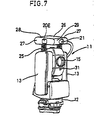
- Fig. 7 shows a second embodiment.
- a handle portion 25 is attached to the upper part of each of mounting portions 13 of a surveying machine body, and a box-shaped body 26 is attached to the handle portion 25.
- Rough-direction detecting devices 20 are disposed on both sides 27 and the rear side 28 of the box-shaped body 26, and a precise-direction detecting device 21 is disposed on the front side 29 of the box-shaped body 26. According to this construction, a surveying system of the present invention can be realized without varying the surveying machine 11 to a large extent.
- the rough-direction detecting devices 20 and the precise-direction detecting device 21 are disclosed above the mounting portions 13, and thereby movements in up and down directions are limited in comparison with the integrally-formed type of automatic surveying machine 11 (see Fig. 2) shown in the first embodiment.
- a light-receiving area becomes smaller apparently, and thereby the output of a photoelectrically-converted signal becomes relatively small in comparison with that in the case where the beam of signal light P3 comes from the horizontal direction.
- an optical point P4 is formed at a position away from the light receiving element 23. This makes it impossible to detect accurately the direction from which the beam of signal light P3 comes. In the case where the beam of signal light P3 comes from a right upper part or a right lower part in the vertical direction, light reception becomes difficult.
- all that have to be done is to dispose the rough-direction detecting device 20 on the side right above or below the surveying machine 11 in the vertical direction, or to increase a condensed-light quantity by providing each of the rough-direction detecting devices 20 with a condensing lens.
- a received-light quantity may be increased by disposing a plurality of rough-direction detecting devices 20 in one plane.
- a light receiving portion 21F of the precise-direction detecting device 21 can be constructed to be rotatable around a rotational center O in the vertical direction. According to this construction, when the light receiving portion 21F of the precise-direction detecting device 21 is rotated such that the optical point P4 is positioned at the origin a(0, 0) of the light receiving element 23, the angle of rotation from the reference position of the light receiving portion 21F of the precise-direction detecting device 21 is measured and detected, and then the value is inputted to the CPU 24 of the surveying machine 11. Thereby, a sight axis of the surveying machine 11 can be turned in the direction from which the beam of signal light P3 comes.
- a reflecting mirror 30 which is rotatable around the rotational center O in the vertical direction can be disposed inside the light receiving portion 21F of the precise-direction detecting device 21.
- the reflecting mirror 30 is rotated in the vertical direction by a pulse motor or a motor having an encoder so that the optical point P4 is positioned at the origin a(0, 0) of the light receiving element 23, and thus the angle of rotation from the reference position of the reflecting mirror 30 can be measured.
- a pulse motor or a motor having an encoder so that the optical point P4 is positioned at the origin a(0, 0) of the light receiving element 23, and thus the angle of rotation from the reference position of the reflecting mirror 30 can be measured.
- the value is inputted to the CPU 24 of the surveying machine 11, so that the sight axis of the surveying machine 11 can be turned in the direction from which the beam of signal light P3 comes.
- an element small in area can be used as the light receiving element 23.
- Pieces of control information about the surveying machine 11 can be accumulated in the beam of signal light P3. For example, if a command to turn on and off a power source of the surveying machine 11, control information about rotating the surveying machine 11 rightward and leftward in the horizontal direction, and control information about rotating the surveying machine 11 upward and downward in the vertical direction are transmitted to the surveying machine 11, the surveying machine 11 can be controlled effectively. Further, if the telescope portion 14 is provided with a point-setting-light portion 31 so that an operator can view the point light, a sighting operation can be performed with heightened accuracy.
- a through-light data transmitter 33 is attached to the telescope portion 14 and a light data transmitter 34 is attached to the pole 4, according to the need, information about measurement results, and information about the surveying machine 11, such as control data, can be given to an operator on the side of the target point B.
- the beam of distance-measuring light P1 is used as transmission light by the light data transmitter 33, or in the case of using a tracking type of surveying machine, a beam of tracking light is used.
- a surveyed-data transmitting function can be added without complicating the construction of the surveying machine 11 to a large extent.
- this invention is constructed such that the direction from which the beam of signal light P3 comes is detected by the rough-direction detecting devices 20, the precise-direction detecting device 21 is then turned to the direction, the direction is then detected accurately by the precise-direction detecting device 21, and the sight axis of the surveying machine 11 is caused to coincide with the target point B.
- the light receiving element 23, which is used in the case where the direction from which the beam of signal light P3 comes is detected, is not limited to a CCD for detecting a two-dimensional position. Instead, a construction may be employed in which a two-dimensional position of the optical point P4 is detected by disposing one-dimensional detecting elements in the directions perpendicular to each other.
- a construction may be employed in which a one-dimension detecting element is disposed only in the vertical direction.
- the surveying machine 11 is rotated in the horizontal direction and is temporarily stopped its rotation immediately before the optical point P4 comes across the one-dimension detecting element, and thereafter the surveying machine 11 is rotated slowly in the same direction, and it is detected when the optical point P4 has come across the one-dimensional detecting element. Therefore, the surveying machine 11 is rotated slowly in the opposite direction from the time when it has come across the one-dimension detecting element by the rotational inertia of the surveying machine 11 and has stopped. This operation is repeated several times, and thereby, for a while, the position where the optical point P4 is imaged can be converged on the one-dimension detecting element.
Landscapes
- Physics & Mathematics (AREA)
- Engineering & Computer Science (AREA)
- General Physics & Mathematics (AREA)
- Radar, Positioning & Navigation (AREA)
- Remote Sensing (AREA)
- Measurement Of Optical Distance (AREA)
- Optical Radar Systems And Details Thereof (AREA)
- Length Measuring Devices By Optical Means (AREA)
Applications Claiming Priority (3)
| Application Number | Priority Date | Filing Date | Title |
|---|---|---|---|
| JP06066496A JP3741477B2 (ja) | 1996-03-18 | 1996-03-18 | 測量システム |
| JP60664/96 | 1996-03-18 | ||
| JP6066496 | 1996-03-18 |
Publications (3)
| Publication Number | Publication Date |
|---|---|
| EP0797076A2 EP0797076A2 (en) | 1997-09-24 |
| EP0797076A3 EP0797076A3 (en) | 1998-10-07 |
| EP0797076B1 true EP0797076B1 (en) | 2005-11-16 |
Family
ID=13148836
Family Applications (1)
| Application Number | Title | Priority Date | Filing Date |
|---|---|---|---|
| EP97250082A Expired - Lifetime EP0797076B1 (en) | 1996-03-18 | 1997-03-18 | Surveying system |
Country Status (4)
| Country | Link |
|---|---|
| US (1) | US6023326A (ja) |
| EP (1) | EP0797076B1 (ja) |
| JP (1) | JP3741477B2 (ja) |
| DE (1) | DE69734623T2 (ja) |
Families Citing this family (60)
| Publication number | Priority date | Publication date | Assignee | Title |
|---|---|---|---|---|
| JP3784154B2 (ja) * | 1997-11-14 | 2006-06-07 | 株式会社トプコン | 測量機の通信システム |
| JP3805504B2 (ja) * | 1997-11-14 | 2006-08-02 | 株式会社トプコン | 測量機の通信システム |
| DE19833996C1 (de) * | 1998-07-29 | 1999-12-09 | Zeiss Carl Jena Gmbh | Elektronisches Nivellier und Verfahren zur Videoanzielung |
| US6138367A (en) * | 1998-08-14 | 2000-10-31 | Trimble Navigation Limited | Tilt prediction for total station |
| JP4320099B2 (ja) * | 1999-03-26 | 2009-08-26 | 株式会社トプコン | 測量装置 |
| DE19914174A1 (de) | 1999-03-29 | 2000-10-12 | Wernicke & Co Gmbh | Verfahren und Vorrichtung zum Formbearbeiten des Umfangsrandes von Brillengläsern |
| JP4210792B2 (ja) * | 1999-06-15 | 2009-01-21 | 株式会社トプコン | 位置検出装置 |
| US6619406B1 (en) * | 1999-07-14 | 2003-09-16 | Cyra Technologies, Inc. | Advanced applications for 3-D autoscanning LIDAR system |
| US6633290B1 (en) | 2000-05-18 | 2003-10-14 | Cyra Technologies, Inc. | Apparatus and method for forming 2D views of a structure from 3D point data |
| US6804380B1 (en) | 2000-05-18 | 2004-10-12 | Leica Geosystems Hds, Inc. | System and method for acquiring tie-point location information on a structure |
| US6604068B1 (en) | 2000-05-18 | 2003-08-05 | Cyra Technologies, Inc. | System and method for concurrently modeling any element of a model |
| US6771840B1 (en) * | 2000-05-18 | 2004-08-03 | Leica Geosystems Hds, Inc. | Apparatus and method for identifying the points that lie on a surface of interest |
| DE10066379B4 (de) * | 2000-05-20 | 2008-07-10 | Trimble Jena Gmbh | Verfahren und Einrichtung zur Realisierung eines Informations- und Datenflusses für geodätische Geräte |
| JP4614506B2 (ja) * | 2000-07-24 | 2011-01-19 | 株式会社トプコン | 携帯型測距装置 |
| KR20020097172A (ko) | 2001-02-08 | 2002-12-31 | 닛폰 고칸 가부시키가이샤 | 3차원 좌표 계측방법, 3차원 좌표 계측장치 및 대형구조물의 건조방법 |
| JP4127503B2 (ja) | 2002-11-22 | 2008-07-30 | 株式会社トプコン | 反射体自動追尾装置 |
| SE525290C2 (sv) * | 2002-12-20 | 2005-01-25 | Trimble Ab | Geodetiskt system för mätning/utsättning och metod för användning av detsamma |
| US6874239B1 (en) | 2004-01-06 | 2005-04-05 | Troy White | Self-holding and self-leveling device for survey range pole and method of use |
| JP4177765B2 (ja) * | 2004-01-30 | 2008-11-05 | 株式会社 ソキア・トプコン | 測量システム |
| JP4177784B2 (ja) * | 2004-05-14 | 2008-11-05 | 株式会社 ソキア・トプコン | 測量システム |
| EP1734336A1 (de) * | 2005-06-13 | 2006-12-20 | Leica Geosystems AG | Geodätisches Zielobjekt und Vermessungssystem |
| US7243434B1 (en) * | 2006-01-08 | 2007-07-17 | Fred Zucker | Laser theodolite and kit for converting a new or pre-existing theodolite into a laser theodolite |
| DE102007055439A1 (de) * | 2007-11-21 | 2009-05-28 | Hilti Aktiengesellschaft | Rotationslaser mit Fernsteuerung |
| JP5150229B2 (ja) * | 2007-12-07 | 2013-02-20 | 株式会社トプコン | 測量システム |
| JP5150234B2 (ja) * | 2007-12-14 | 2013-02-20 | 株式会社トプコン | 測量装置 |
| US8024866B2 (en) * | 2008-10-21 | 2011-09-27 | Agatec | Height recording system comprising a telescopic rule with two ends cooperating with an optical beam scanning in a horizontal plane |
| US9482755B2 (en) | 2008-11-17 | 2016-11-01 | Faro Technologies, Inc. | Measurement system having air temperature compensation between a target and a laser tracker |
| WO2012141810A1 (en) | 2011-03-03 | 2012-10-18 | Faro Technologies, Inc. | Target apparatus and method |
| EP2194399A1 (de) * | 2008-12-03 | 2010-06-09 | Leica Geosystems AG | Positionsbestimmungsverfahren und geodätisches Vermessungssystem |
| EP2224205A1 (de) * | 2009-02-25 | 2010-09-01 | Leica Geosystems AG | Nivelliergerät und Verfahren zum Nivellieren |
| US8769838B2 (en) * | 2009-09-28 | 2014-07-08 | Warren Dale Ward | Surveyor 's rod and magnetic locator |
| US9400170B2 (en) | 2010-04-21 | 2016-07-26 | Faro Technologies, Inc. | Automatic measurement of dimensional data within an acceptance region by a laser tracker |
| US8724119B2 (en) | 2010-04-21 | 2014-05-13 | Faro Technologies, Inc. | Method for using a handheld appliance to select, lock onto, and track a retroreflector with a laser tracker |
| US8619265B2 (en) | 2011-03-14 | 2013-12-31 | Faro Technologies, Inc. | Automatic measurement of dimensional data with a laser tracker |
| US8537371B2 (en) | 2010-04-21 | 2013-09-17 | Faro Technologies, Inc. | Method and apparatus for using gestures to control a laser tracker |
| US8422034B2 (en) | 2010-04-21 | 2013-04-16 | Faro Technologies, Inc. | Method and apparatus for using gestures to control a laser tracker |
| US9377885B2 (en) | 2010-04-21 | 2016-06-28 | Faro Technologies, Inc. | Method and apparatus for locking onto a retroreflector with a laser tracker |
| US9772394B2 (en) | 2010-04-21 | 2017-09-26 | Faro Technologies, Inc. | Method and apparatus for following an operator and locking onto a retroreflector with a laser tracker |
| US9686532B2 (en) | 2011-04-15 | 2017-06-20 | Faro Technologies, Inc. | System and method of acquiring three-dimensional coordinates using multiple coordinate measurement devices |
| US9164173B2 (en) | 2011-04-15 | 2015-10-20 | Faro Technologies, Inc. | Laser tracker that uses a fiber-optic coupler and an achromatic launch to align and collimate two wavelengths of light |
| US9482529B2 (en) | 2011-04-15 | 2016-11-01 | Faro Technologies, Inc. | Three-dimensional coordinate scanner and method of operation |
| JP2014516409A (ja) | 2011-04-15 | 2014-07-10 | ファロ テクノロジーズ インコーポレーテッド | レーザトラッカの改良位置検出器 |
| US9222771B2 (en) | 2011-10-17 | 2015-12-29 | Kla-Tencor Corp. | Acquisition of information for a construction site |
| US8720074B2 (en) * | 2011-12-06 | 2014-05-13 | Trimble Navigation Limited | Robotic leveling |
| JP6099675B2 (ja) | 2012-01-27 | 2017-03-22 | ファロ テクノロジーズ インコーポレーテッド | バーコード識別による検査方法 |
| US9041914B2 (en) | 2013-03-15 | 2015-05-26 | Faro Technologies, Inc. | Three-dimensional coordinate scanner and method of operation |
| US9234742B2 (en) | 2013-05-01 | 2016-01-12 | Faro Technologies, Inc. | Method and apparatus for using gestures to control a laser tracker |
| EP2801839B1 (de) | 2013-05-10 | 2020-03-04 | Leica Geosystems AG | Handhaltbares Messhilfsmittel zur Verwendung mit einem 6-DoF-Lasertracker |
| JP6209021B2 (ja) | 2013-08-23 | 2017-10-04 | 株式会社トプコン | 測量機 |
| JP6227324B2 (ja) | 2013-08-23 | 2017-11-08 | 株式会社トプコン | 測量機及び測量作業システム |
| US9395174B2 (en) | 2014-06-27 | 2016-07-19 | Faro Technologies, Inc. | Determining retroreflector orientation by optimizing spatial fit |
| WO2016073208A1 (en) | 2014-11-03 | 2016-05-12 | Faro Technologies, Inc. | Method and apparatus for locking onto a retroreflector with a laser tracker |
| JP6490401B2 (ja) * | 2014-11-12 | 2019-03-27 | 株式会社トプコン | 傾斜検出システム及び傾斜検出方法 |
| JP2019507349A (ja) | 2016-02-29 | 2019-03-14 | ファロ テクノロジーズ インコーポレーテッド | レーザー・トラッカー・システム |
| JP6963909B2 (ja) | 2017-05-10 | 2021-11-10 | 株式会社トプコン | 測量システム |
| JP6855316B2 (ja) * | 2017-05-10 | 2021-04-07 | 株式会社トプコン | 測量システム |
| US11320263B2 (en) * | 2019-01-25 | 2022-05-03 | Stanley Black & Decker Inc. | Laser level system |
| EP3734222A1 (en) * | 2019-05-02 | 2020-11-04 | Leica Geosystems AG | Coordinate measuring and/or stake out device |
| CN110411408A (zh) * | 2019-07-11 | 2019-11-05 | 浙江大学 | 一种基于计算机视觉的地表沉降监测方法 |
| CN112815929B (zh) * | 2020-12-31 | 2022-03-29 | 美国西北仪器公司 | 使用激光扫平仪追踪探测器的方法及激光追踪系统 |
Family Cites Families (10)
| Publication number | Priority date | Publication date | Assignee | Title |
|---|---|---|---|---|
| BE787649A (fr) * | 1971-09-20 | 1973-02-19 | Blount & George Inc | Systeme de poursuite ou de depistage a l'aide d'un instrument d'optiqu |
| CH640050A5 (de) * | 1978-07-20 | 1983-12-15 | Kern & Co Ag | Verfahren und vorrichtung zur messung der relativlage zwischen einem ersten und mindestens einem zweiten punkt. |
| US4413907A (en) * | 1980-11-07 | 1983-11-08 | Robert F. Deike | Remote control surveying |
| US4830489A (en) * | 1986-08-20 | 1989-05-16 | Spectra-Physics, Inc. | Three dimensional laser beam survey system |
| US4820041A (en) * | 1986-11-12 | 1989-04-11 | Agtek Development Co., Inc. | Position sensing system for surveying and grading |
| CH676041A5 (en) * | 1988-07-22 | 1990-11-30 | Wild Leitz Ag | Surveying unit with theodolite and range finder - determines fine coordinates from coarsely determined target points and has light pulse transmitter and receiver |
| SE500856C2 (sv) * | 1989-04-06 | 1994-09-19 | Geotronics Ab | Arrangemang att användas vid inmätnings- och/eller utsättningsarbete |
| JPH032513A (ja) * | 1989-05-30 | 1991-01-08 | Tatsushi Miyahara | 自動測量装置 |
| JP3090781B2 (ja) * | 1992-05-22 | 2000-09-25 | 株式会社トプコン | 測量機 |
| JP3075384B2 (ja) * | 1993-09-16 | 2000-08-14 | 株式会社トプコン | 測量装置 |
-
1996
- 1996-03-18 JP JP06066496A patent/JP3741477B2/ja not_active Expired - Fee Related
-
1997
- 1997-03-18 DE DE69734623T patent/DE69734623T2/de not_active Expired - Lifetime
- 1997-03-18 EP EP97250082A patent/EP0797076B1/en not_active Expired - Lifetime
- 1997-03-18 US US08/820,653 patent/US6023326A/en not_active Expired - Lifetime
Also Published As
| Publication number | Publication date |
|---|---|
| JP3741477B2 (ja) | 2006-02-01 |
| DE69734623T2 (de) | 2006-07-13 |
| DE69734623D1 (de) | 2005-12-22 |
| JPH09250927A (ja) | 1997-09-22 |
| EP0797076A2 (en) | 1997-09-24 |
| US6023326A (en) | 2000-02-08 |
| EP0797076A3 (en) | 1998-10-07 |
Similar Documents
| Publication | Publication Date | Title |
|---|---|---|
| EP0797076B1 (en) | Surveying system | |
| US6462810B1 (en) | Surveying system | |
| EP3450917B1 (en) | Surveying system | |
| EP2103902B1 (en) | Surveying Device and Surveying System | |
| EP1061335B1 (en) | Position detecting apparatus | |
| US11402506B2 (en) | Laser measuring method and laser measuring instrument | |
| US5610711A (en) | Remote pointing system for a self-leveling laser instrument | |
| US6801305B2 (en) | Device for optically measuring distances | |
| JP3268608B2 (ja) | 測量装置 | |
| US6957493B2 (en) | Automatic tracking apparatus for reflector | |
| EP1024343A2 (en) | Rotary laser irradiating system | |
| JP3784154B2 (ja) | 測量機の通信システム | |
| EP1016850A2 (en) | Rotary laser irradiating system | |
| JP2003214851A (ja) | ターゲットマークを自動検索する方法、ターゲットマークを自動検索する装置、受信ユニット、測地計および測地システム | |
| JP6749192B2 (ja) | スキャナ装置および測量装置 | |
| EP1380812A1 (en) | Laser irradiating system | |
| JP2521754B2 (ja) | 測量装置 | |
| JPH07190773A (ja) | 光学式3次元位置検出装置 | |
| JP3155188B2 (ja) | 自動追尾装置 | |
| JPH08150582A (ja) | 移動ロボット走行システム | |
| US5959739A (en) | System for distinguishing true target reflections from ghost target reflections | |
| JPH09113603A (ja) | 移動体の位置検出装置 | |
| JP2019015602A (ja) | 測量システム | |
| JPH05250033A (ja) | 自動誘導システム | |
| CN113759351A (zh) | 一种激光雷达接收端校准系统及方法 |
Legal Events
| Date | Code | Title | Description |
|---|---|---|---|
| PUAI | Public reference made under article 153(3) epc to a published international application that has entered the european phase |
Free format text: ORIGINAL CODE: 0009012 |
|
| 17P | Request for examination filed |
Effective date: 19970318 |
|
| AK | Designated contracting states |
Kind code of ref document: A2 Designated state(s): CH DE LI SE |
|
| PUAL | Search report despatched |
Free format text: ORIGINAL CODE: 0009013 |
|
| AK | Designated contracting states |
Kind code of ref document: A3 Designated state(s): CH DE LI SE |
|
| 17Q | First examination report despatched |
Effective date: 20020705 |
|
| GRAP | Despatch of communication of intention to grant a patent |
Free format text: ORIGINAL CODE: EPIDOSNIGR1 |
|
| GRAS | Grant fee paid |
Free format text: ORIGINAL CODE: EPIDOSNIGR3 |
|
| GRAA | (expected) grant |
Free format text: ORIGINAL CODE: 0009210 |
|
| AK | Designated contracting states |
Kind code of ref document: B1 Designated state(s): CH DE LI SE |
|
| REG | Reference to a national code |
Ref country code: CH Ref legal event code: EP |
|
| REG | Reference to a national code |
Ref country code: SE Ref legal event code: TRGR |
|
| REF | Corresponds to: |
Ref document number: 69734623 Country of ref document: DE Date of ref document: 20051222 Kind code of ref document: P |
|
| REG | Reference to a national code |
Ref country code: CH Ref legal event code: NV Representative=s name: BRAUNPAT BRAUN EDER AG |
|
| PLBE | No opposition filed within time limit |
Free format text: ORIGINAL CODE: 0009261 |
|
| STAA | Information on the status of an ep patent application or granted ep patent |
Free format text: STATUS: NO OPPOSITION FILED WITHIN TIME LIMIT |
|
| 26N | No opposition filed |
Effective date: 20060817 |
|
| PGFP | Annual fee paid to national office [announced via postgrant information from national office to epo] |
Ref country code: SE Payment date: 20130312 Year of fee payment: 17 Ref country code: CH Payment date: 20130312 Year of fee payment: 17 |
|
| REG | Reference to a national code |
Ref country code: CH Ref legal event code: PL |
|
| REG | Reference to a national code |
Ref country code: SE Ref legal event code: EUG |
|
| PG25 | Lapsed in a contracting state [announced via postgrant information from national office to epo] |
Ref country code: SE Free format text: LAPSE BECAUSE OF NON-PAYMENT OF DUE FEES Effective date: 20140319 |
|
| PG25 | Lapsed in a contracting state [announced via postgrant information from national office to epo] |
Ref country code: LI Free format text: LAPSE BECAUSE OF NON-PAYMENT OF DUE FEES Effective date: 20140331 Ref country code: CH Free format text: LAPSE BECAUSE OF NON-PAYMENT OF DUE FEES Effective date: 20140331 |
|
| PGFP | Annual fee paid to national office [announced via postgrant information from national office to epo] |
Ref country code: DE Payment date: 20150310 Year of fee payment: 19 |
|
| REG | Reference to a national code |
Ref country code: DE Ref legal event code: R119 Ref document number: 69734623 Country of ref document: DE |
|
| PG25 | Lapsed in a contracting state [announced via postgrant information from national office to epo] |
Ref country code: DE Free format text: LAPSE BECAUSE OF NON-PAYMENT OF DUE FEES Effective date: 20161001 |