EP0796993A2 - Zündapparat für eine Brennkraftmaschine - Google Patents
Zündapparat für eine Brennkraftmaschine Download PDFInfo
- Publication number
- EP0796993A2 EP0796993A2 EP97104865A EP97104865A EP0796993A2 EP 0796993 A2 EP0796993 A2 EP 0796993A2 EP 97104865 A EP97104865 A EP 97104865A EP 97104865 A EP97104865 A EP 97104865A EP 0796993 A2 EP0796993 A2 EP 0796993A2
- Authority
- EP
- European Patent Office
- Prior art keywords
- internal combustion
- combustion engine
- ignition apparatus
- coil
- ignitor
- Prior art date
- Legal status (The legal status is an assumption and is not a legal conclusion. Google has not performed a legal analysis and makes no representation as to the accuracy of the status listed.)
- Granted
Links
Images


Classifications
-
- F—MECHANICAL ENGINEERING; LIGHTING; HEATING; WEAPONS; BLASTING
- F02—COMBUSTION ENGINES; HOT-GAS OR COMBUSTION-PRODUCT ENGINE PLANTS
- F02P—IGNITION, OTHER THAN COMPRESSION IGNITION, FOR INTERNAL-COMBUSTION ENGINES; TESTING OF IGNITION TIMING IN COMPRESSION-IGNITION ENGINES
- F02P3/00—Other installations
- F02P3/02—Other installations having inductive energy storage, e.g. arrangements of induction coils
-
- H—ELECTRICITY
- H01—ELECTRIC ELEMENTS
- H01F—MAGNETS; INDUCTANCES; TRANSFORMERS; SELECTION OF MATERIALS FOR THEIR MAGNETIC PROPERTIES
- H01F38/00—Adaptations of transformers or inductances for specific applications or functions
- H01F38/12—Ignition, e.g. for IC engines
-
- H—ELECTRICITY
- H01—ELECTRIC ELEMENTS
- H01T—SPARK GAPS; OVERVOLTAGE ARRESTERS USING SPARK GAPS; SPARKING PLUGS; CORONA DEVICES; GENERATING IONS TO BE INTRODUCED INTO NON-ENCLOSED GASES
- H01T13/00—Sparking plugs
- H01T13/40—Sparking plugs structurally combined with other devices
- H01T13/44—Sparking plugs structurally combined with other devices with transformers, e.g. for high-frequency ignition
-
- H—ELECTRICITY
- H01—ELECTRIC ELEMENTS
- H01F—MAGNETS; INDUCTANCES; TRANSFORMERS; SELECTION OF MATERIALS FOR THEIR MAGNETIC PROPERTIES
- H01F38/00—Adaptations of transformers or inductances for specific applications or functions
- H01F38/12—Ignition, e.g. for IC engines
- H01F2038/122—Ignition, e.g. for IC engines with rod-shaped core
Definitions
- the present invention relates to an ignition apparatus for use in an internal combustion engine and more particularly relates to a cylindrical form ignition apparatus for use in an internal combustion engine which is received in a plug hole portion of the internal combustion engine.
- the present invention relates to a cylindrical form ignition apparatus for use in an internal combustion engine comprising a cylindrical form side core having a slit between vertical side wall ends, and this side core having the slit is constituted by selected one from a single grain oriented silicon steel sheet, a single grain non-oriented silicon steel sheet, a laminated structure of at least two comprised of a grain oriented silicon steel sheet and a grain non-oriented silicon steel sheet, and a laminated structure of at least two grain oriented silicon steel sheets.
- the present invention relates to a cylindrical form ignition apparatus for use in an internal combustion engine having a reception body comprised of an ignitor case part and a coil case part, and the reception body comprises an independent and individual ignitor reception portion for receiving the ignitor case part having a connector and an independent and individual coil reception portion for receiving the coil case part.
- the present invention relates to an ignition apparatus for use in an internal combustion engine and in particularly to a sealing structure of a cylindrical form ignition apparatus which is received in a plug hole portion of the internal combustion engine.
- a side core of the ignition apparatus is formed in a spiral form by multiplex winding and laminating with a single grain non-oriented silicon steel sheet to an outer case of the ignition apparatus.
- the side core includes the grain non-oriented silicon steel sheet of having silicon of 6.5 wt% degree and the grain non-oriented silicon steel sheet has a sheet thickness of 0.1 mm.
- the ignition apparatus requires much time for manufacturing the side core in the spiral form and it invites a high cost ignition apparatus for use in the internal combustion engine.
- the side core structure in the above stated conventional ignition apparatus overlaps multiplex and completely a whole outside periphery portion of the outer case, in other words, the side core structure forms no gap or no space on the outside periphery portion of the outer case toward an outside periphery horizontal direction of the outer case.
- the conventional ignition apparatus has a low secondary voltage and according to the circumferences the conventional ignition apparatus cannot obtain a necessary secondary voltage and then the ignition apparatus cannot spark surely to the internal combustion engine.
- the side core is wound round to have a substantially same cross-sectional area of a center core.
- the ignition apparatus has two magnets provided on both ends of the center core. These magnets generate in a magnetic path an opposite side direction magnetic flux against a magnetic flux generated by a primary coil. As a result, it invites a high cost ignition apparatus for use in the internal combustion engine.
- the ignition apparatus has an outer case and an ignitor case part (IC package type unit) and a cylindrical form ignition apparatus main body are embodied as an integral body, and a connector is integrally formed to the ignitor case part and is adjacently arranged to an upper portion of the ignitor case part.
- IC package type unit ignitor case part
- main body cylindrical form ignition apparatus main body
- the outer case of an ignitor reception portion projects toward an upper portion of the plug hole. Further, the outer case of the ignitor reception portion has a complicated form having a step portion.
- the ignition apparatus arranges adjacently to a combustion chamber of an internal combustion engine, an environment temperature in the plug hole reaches to 150 °C at maximum. Therefore, the ignition apparatus is necessary to correspond against a severe heat resistance environment condition.
- the connector is necessary to correspond against a shock force.
- a shock force is added during an mounting time and an installing time or during a maintenance time of the ignition apparatus.
- the ignition apparatus is necessary to correspond against a connector having a different specification in accordance with a kind of the internal combustion engine and a kind of a control apparatus.
- a sealing structure of the ignition apparatus has a sealing rubber member which prevents water leakage from a plug hole portion to a cylinder head cover of the internal combustion engine.
- the sealing rubber member is received fully in an interior portion of the plug hole portion and the received rubber portion of the sealing rubber member seals at a radial direction of the plug hole portion.
- An object of the present invention is to provide an ignition apparatus for use in an internal combustion engine wherein an effective magnetic flux of a center core portion can pass with the most efficiency.
- Another object of the present invention is to provide an ignition apparatus for use in an internal combustion engine wherein a floating capacity generated between a secondary coil and a side core can rationally delete.
- a further object of the present invention is to provide an ignition apparatus for use in an internal combustion engine wherein a thickness or a length of a side core can vary in accordance with a material and a length of a cylinder head or a cylinder head cover of the internal combustion engine in which a plug hole portion for receiving the ignition apparatus is formed.
- a further object of the present invention is to provide an ignition apparatus for use in an internal combustion engine wherein a number or a thickness of a magnet inserted on one end of a center core or both ends of the center core can vary and, as a result a low cost ignition apparatus for use in an internal combustion engine can obtain.
- a further object of the present invention is to provide an ignition apparatus for use in an internal combustion engine wherein an ignition apparatus can correspond to a difference in an actual amounted environment condition or to various required connector specifications.
- a further object of the present invention is to provide an ignition apparatus for use in an internal combustion engine where an ignition apparatus. having a superior high reliability can be obtained.
- a further object of the present invention is to provide an ignition apparatus for use in an internal combustion engine where a position slip-off between a sealing rubber member and a plug hole portion can be seal surely.
- a further object of the present invention is to provide an ignition apparatus for use in an internal combustion engine where a position slip-off between a sealing rubber member and a plug hole portion can be seal surely.
- an ignition apparatus for use in an internal combustion engine comprises a center core, a primary coil wound round on a primary bobbin, a secondary coil wound round on a secondary bobbin, an outer case, and a side core arranged on an outer peripherally of the outer case and made by using a silicon steel sheet, the primary coil and the secondary coil arranged between the center core and the outer case, the ignition apparatus is received in a plug hole which is formed by a cylinder head and a cylinder head cover of the internal combustion engine.
- the side core has a slit between two horizontally extending side wall ends and the slit prevents an one-turn short of a magnetic flux of the side core, thereby a predetermined secondary voltage more than an engine requirement secondary voltage is obtained.
- the side core is formed by making round in the substantially pipe form with, for example, one sheet of the single grain oriented silicon steel sheet having the sheet thickness of 0.3-0.5 mm or one sheet of the single grain non-oriented silicon steel sheet having the sheet thickness of 0.3-0.5 mm.
- the side core is formed by making round in the substantially pipe form and laminating with, for example, two sheets or three sheets of the grain oriented silicon steel sheet having the sheet thickness of 0.3-0.5 mm per one sheet and then the side core has the total sheet thickness of more than 0.6 mm or one sheet of the single grain non-oriented silicon steel sheet having the sheet thickness of 0.3-0.5 mm and at least one sheet of the grain oriented silicon steel sheet having the sheet thickness of 0.3-0.5 mm per one sheet and then the side core has the total sheet thickness of more than 0.6 mm.
- the upper end of the side core positions substantial same to the upper end of the cylinder head cover, or the upper end of the side core positions lower than the upper end of the center core.
- the side core is formed by making round in the substantially pipe form, for example, one sheet of the single grain oriented silicon steel sheet having the sheet thickness of 0.3-0.5 mm or one sheet of the single grain non-oriented silicon steel sheet having the sheet thickness of 0.3-0.5 mm.
- the side core is formed by making round in the substantially pipe form and laminating with, for example, two sheets or three sheets of the grain oriented silicon steel sheet having the sheet thickness of 0.3-0.5 mm per one sheet and then the side core has the total sheet thickness of more than 0.6 mm or one sheet of the single grain non-oriented silicon steel sheet having the sheet thickness of 0.3-0.5 mm and at least one sheet of the grain oriented silicon steel sheet having the sheet thickness of 0.3-0.5 mm per one sheet and then the side core has the total sheet thickness of more than 0.6 mm.
- the upper end of the side core positions substantial same to the upper end of the cylinder head, or the upper end of the side core positions lower than the upper end of the center core.
- the side core is formed by making round in the substantially pipe form, for example, one sheet of the single grain oriented silicon steel sheet having the sheet thickness of 0.3-0.5 mm or one sheet of the single grain non-oriented silicon steel sheet having the sheet thickness of 0.3-0.5 mm.
- the side core is formed by making round in the substantially pipe form, two sheets or three sheets of the grain oriented silicon steel sheet having the sheet thickness of 0.3-0.5 mm per one sheet and then the side core has the total sheet thickness of more than 0.6 mm or one sheet of the grain non-oriented silicon steel sheet having the sheet thickness of 0.3-0.5 mm and at least one sheet of the grain oriented silicon steel sheet having the sheet thickness of 0.3-0.5 mm per one sheet and then the side core has the total sheet thickness of more than 0.6 mm.
- the upper end of the side core positions substantial same to the higher upper end selected one from the upper end of the cylinder head and the upper end of the iron made plug tube, or the upper end of the side core positions lower than the upper end of the center core.
- the magnet generates in the magnetic path the opposite side direction magnetic flux against the magnetic flux generated by the primary coil and the magnet is provided on one end of the center core or on both ends of the center core.
- both the cylinder head and the cylinder head cover are made by using the aluminum material together with, by inserting the magnet on the both ends of the side core, the good efficiency magnetic flux can generate.
- the good efficiency magnetic flux can generate.
- the more good efficiency magnetic flux can generate by inserting the magnet to the center core at the side of the aluminum made cylinder head than the side of the thermoplastic synthetic resin material made cylinder head cover, thereby a low cost ignition apparatus for use in an internal combustion engine can obtain.
- an ignition apparatus for use in an internal combustion engine comprises a center core, a primary coil wound round on a primary bobbin, a secondary coil wound round on a secondary bobbin, an outer case, a side core arranged on an outer periphery of the outer case, and a reception body for receiving an ignitor case part and a coil case part, the ignitor case part having an electrically and adjacently arranged connector, the primary coil and the secondary coil arranged between the center core and the outer case.
- the ignitor reception portion comprises an independent and individual ignitor reception portion and an independent and individual coil reception portion, and the ignitor reception portion and the coil reception portion are combined.
- an ignition apparatus for use in an internal combustion engine comprises a center core, a primary coil wound round on a primary bobbin, a secondary coil wound round on a secondary bobbin, an outer case, a side core arranged on an outer periphery of the outer case, a reception body for receiving an ignitor case part and a coil case part, the ignitor case part having an electrically and adjacently arranged connector, and a sealing member for sealing an environment of an inside and an outside of a plug hole portion of the internal combustion engine, the primary coil and the secondary coil arranged between the center core and the outer case.
- the ignitor reception portion comprises an independent and individual ignitor reception portion and an independent and individual coil reception portion, the ignitor reception portion receives the ignitor case part at a portion where the sealing member fits into and inserts, and the ignitor reception portion and the coil reception portion are combined.
- an ignition apparatus for use in an internal combustion engine comprising an ignitor part having an electrically connected and adjacently arranged connector, and a coil case part, and a reception body for receiving the ignitor part and the coil case part.
- the ignition apparatus for use in the internal combustion engine comprises a reception body has two parts comprised of an independent and individual coil reception portion and an independent and individual ignitor reception portion.
- the coil reception portion receives the coil case part and is inserted into a standardized plug hole of an internal combustion engine, and the ignitor reception portion receives the ignitor case part and is arranged at outside of the plug hole and has the connector which can connect to the other connector having a different specification.
- the coil reception portion and the ignitor reception portion are integrally combined at a combination portion.
- an ignition apparatus for use an internal combustion engine comprising an ignitor case part having an electrically connected and adjacently arranged connector, and a coil case part, a reception body for receiving the ignitor case part and the coil case part, and a sealing body for sealing an environment of an inside and an outside of a plug hole, which fits into and inserts into the reception body, of the internal combustion engine.
- the ignition apparatus for use in the internal combustion engine comprises the reception body has two part comprised of an independent and individual coil reception portion and an independent and individual ignitor reception portion at a portion in which the sealing body is fitted into.
- the coil reception portion receives the coil case part and inserts into the plug hole, and the ignitor reception portion receives the ignitor case part and arranges at the outside of the plug hole and has the connector which can connect to the other connector having a different specification.
- the coil reception portion and the ignitor reception portion are integrally combined at the combination portion.
- the ignition apparatus can correspond with a difference in an actual mounted environment condition or various required connector specifications.
- an ignition apparatus for use in an internal combustion engine comprises a center core, a primary coil wound round on a primary bobbin, a secondary coil wound round on a secondary bobbin, an outer case, a side core arranged on an outer periphery of the outer case, the primary coil and the secondary coil arranged between the center core and the outer case, the ignition apparatus is received in a plug tube and a plug hole portion which is formed by a cylinder head, a cylinder head cover of the internal combustion engine, and an ignition plug is arranged at a lower portion of the plug hole portion, the ignition apparatus comprises further an inner cylindrical portion inserted to the plug hole and a sealing rubber member inserted and fitted into the inner cylindrical portion of the ignition apparatus so as to prevent water penetration into the plug hole.
- the sealing rubber comprises a flange portion and a conical portion
- the flange portion of the sealing rubber member has an extension face at a radial direction
- the extension face contacts to a tip end portion of the cylinder head cover from an axial direction side and enable to bend at the axial direction side and to escape a radial direction slip-off
- the conical portion of the sealing rubber member forms a tapering form toward at a direction of the ignition plug so as to guide the sealing rubber member, when the conical portion of the sealing rubber member inserts to the plug tube.
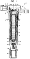
- Fig. 1 a cross-sectional view of one embodiment of an ignition apparatus for use in an internal combustion engine according to the present invention
- Fig. 2 is a horizontal cross-sectional view showing an ignition apparatus for use in an internal combustion engine.
- An ignition apparatus (an ignition coil) 10 for use in an internal combustion engine mainly comprises a primary bobbin 11, a primary coil 12, a secondary bobbin 13, a secondary coil 14, an outer case 15, an epoxy resin material member 16, a center core (an open magnetic path iron core) 17, a side core (an outer iron core) 18, and a flexible epoxy resin material member 19.
- the ignition apparatus (ignition coil) 10 comprises further a magnet 20 arranged at a lower end of the primary bobbin 11, a high voltage terminal 21, a spring member 22, a rubber boot member 23, an advance spark ignition prevention high voltage diode 24, a sealing rubber member 25, and an ignitor unit 30.
- the ignitor unit 30 has a copper or aluminum made box form metal base 36 and this metal base 36 installs a power transistor chip 31, a hybrid IC circuit 38.
- An ignitor terminal 32 is adhered to a terminal stand 37 which is integrally formed with the metal base 36 thorough an adhesive agent 39.
- the ignitor terminal 32 is connected to a primary coil terminal 33 and a connector side terminal 35.
- the ignitor unit 30 has a connector 34.
- the center core 17 is arranged at a center portion of the ignition apparatus 10 and this center core 17 is constituted by laminating under pressing operation of a grain oriented silicon steel sheet.
- the primary bobbin 11 fits into an outer periphery of the center core 17 and the primary coil 12 comprised of am enamel wire etc. is wound round an outer periphery of the primary bobbin 11.
- the secondary bobbin 13 fits into at an outside of the primary bobbin 11.
- the plural divided secondary coil 14 is wound round the secondary bobbin 13 with a predetermined interval.
- the outer case 15 is wound round at an outer periphery of the secondary bobbin 13.
- the outer case 15 comprises an ignitor case part 15a and a coil case part 15b and the above coil case part 15b has a vertically extending projection member 15b1 at an outer portion.
- the side core 18 is arranged at an outside of the coil case part 15b of the outer case 15.
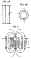
- Fig. 3A is an oblique view showing an inner sheet of a side core of an ignition apparatus for use in an internal combustion engine according to the present invention
- Fig. 3B is an oblique view showing an outer sheet of a side core of an ignition apparatus for use in an internal combustion engine according to the present invention.
- the side core 18 comprises a laminated structure of two silicon steel sheets 18a and 18b which are an inner silicon steel sheet 18a and an outer silicon steel sheet 18b.
- Each of the two silicon steel sheets 18a and 18b is made by using a single grain oriented silicon steel sheet.
- the inner sheet 18a of the side core 18 is made by using the single grain oriented silicon steel sheet having a sheet thickness of 0.35 mm.
- the inner sheet 18a is formed in a substantially pipe form having a vertically extending slit 18a1. This inner sheet 18a fits into the outer periphery of the outer case 15 and the slit 18a1 of the inner sheet 18a positions between a projection member 15b1 of the coil case part 15b.
- This projection member 15b1 of the coil case part 15b is not necessarily to provide on the coil case part 15b.
- the outer sheet 18b of the side core 18 is made by using the single grain oriented silicon steel sheet having a sheet thickness of 0.35 mm.
- the outer steel 18b is formed in a substantially pipe form having a vertically extending slit 18b1. This outer sheet 18b is laminated and overlapped on an outer periphery of the inner sheet 18a.
- a laminated structure of the side core 18 having a total sheet thickness of 0.7 mm comprised of the inner sheet 18a.
- the outer sheet 18b fits to the outside periphery of the outer case 15 and the slit 18b1 of the outer sheet 18b positions between the projection member 15b1 of the coil case part 15b.
- the laminated structure of the side core 18 comprised of the inner sheet 18a and the outer sheet 18b forms a gap (a space) g between the vertical side wall ends of the inner sheet 18a having the slit 18a1 and between the vertical side wall ends of the outer sheet 18b having the slit 18b1.
- the slit 18a1 of the inner sheet 18a for forming the gap g and the slit 18b1 of the outer sheet 18b for forming the gap g can separate electrically by the projection member 15b1 of the coil case part 15b, and the slits 18a1 and 18b1 of the side core 18 prevent an one-turn short of a magnetic flux.
- the established commercial base kinds of the sheet thickness of the silicon steel sheet are four which are 0.23 mm, 0.3 mm, 0.35 mm and 0.5 mm.
- a single sheet structure a single silicon steel sheet having a sheet thickness of 0.5 mm can employ, and a laminated sheet structure of two silicon steel sheets of having a sheet thickness of 0.35 mm (in a total sheet thickness is 0.7 mm) can employ.
- the primary bobbin 11 is manufactured by using a thermoplastic synthetic resin material, for example, denatured polyphenylene oxide (hereinafter, "denatured PPO” etc.).
- a thermoplastic synthetic resin material for example, denatured polyphenylene oxide (hereinafter, "denatured PPO” etc.).
- the above stated primary bobbin 11 is made by using the denatured PPO taking under consideration about an adhesion characteristic with the epoxy resin material member 16.
- the ignition apparatus 10 for use in the internal combustion engine according to the present invention is installed to a plug hole portion of the internal combustion engine, it is preferable to use a thermal deformation temperature of the denatured PPO having more than 150 °C as the material for the primary bobbin 11.
- Fig. 4A is a side view showing a primary bobbin structure having grooves or notches of an ignition apparatus for use in an internal combustion engine according to the present invention
- Fig. 4B is a plan view showing the primary bobbin having the grooves of Fig. 4A.
- each of the grooves 11a and 11b has a depth of 0.1-0.5 mm to easily impregnate the high voltage insulation epoxy resin material member 16 in a winding portion of the primary coil 12.
- the primary coil 12 is laminated and wound round with a total 100-300 times degree enamel wire having a diameter of 0.3-1.0 mm.
- This enamel wire is laminated and wound round extending several layers in which every one extending layer each comprises several ten times.
- the secondary bobbin 13 is manufactured by using a thermoplastic synthetic resin material (for example, the denatured PPO etc.), and the secondary coil 14 is wound round on the secondary bobbin 13.
- the secondary bobbin 13 is arranged between the center core 17 and the secondary coil 14 and the secondary bobbin 13 works a role of an insulation of the high voltage generated in the secondary coil 14.
- the center core 17 floats with the ground (GND)
- the center core 17 has an intermediate potential of the voltage generated in the secondary coil 14.
- the secondary bobbin 14 has a thickness of 0.5-1.2 mm.
- the flexible epoxy resin material member 19 is poured under vacuum condition in an inside portion of the secondary bobbin 13.
- the secondary coil 14 is formed by using the enamel wire having a wire diameter of 0.03-0.06 mm and is dividingly wound round with total 10,000-30,000 times degree.
- the outer case 15 is made by using a thermoplastic synthetic resin material (for example, polybutylene terephthalate (hereinafter, "PBT”) or polyphenylene sulfide (hereinafter, “PPS”) etc..
- a thermoplastic synthetic resin material for example, polybutylene terephthalate (hereinafter, "PBT") or polyphenylene sulfide (hereinafter, “PPS”) etc.
- the above stated outer case 15 has a gate at a side of the high voltage and then an occurrence in voids at the side of the high voltage can prevent.
- the center core 17 is laminated under pressing operation with a grain oriented silicon steel sheet having a sheet thickness of 0.2-0.7 mm per one sheet.
- the side core 18 and the magnet 20, which is provided on a lower portion of the center core 17, are arranged to pass an effective magnetic flux ⁇ x of the center core 17 portion at maximum and to delete rationally a floating capacity C which generates between the secondary coil 14 and the side core 18.
- the effective magnetic flux ⁇ x is divided into a magnetic flux ⁇ 1 of the side core 18 portion and a magnetic flux ⁇ 0 of the plug hole portion of the internal combustion engine.
- the head cover having the one turn short part of the internal combustion engine is made by using an aluminum material
- a relationship between the thickness of the side core 18 and a secondary voltage of the ignition apparatus (ignition coil) 10 is shown as following.
- V 2' ⁇ N x d( ⁇ x - ⁇ 0)/dt wherein, V 2 : a secondary voltage in case of a single ignition apparatus; V 2' : a secondary voltage of the ignition apparatus mounted on the internal combustion engine.
- the side core 18 is formed by laminating with two grain oriented silicon steel sheets having a sheet thickness of 0.35 mm per one sheet and then the side core 18 having the total sheet thickness of 0.7 mm is formed on the outer case 15, as a result, an engine requirement secondary voltage can clear.
- Fig. 6 shows a relationship between the length of the side core 18 and the secondary voltage of the ignition apparatus 10 in case where both a cylinder head and a cylinder head cover of the internal combustion engine are made by using the aluminum material.
- the upper end portion of the side core 18 positions more than the upper end portion of the cylinder head cover or the upper end portion of the side core 18 positions less than about 10 mm of the upper end portion of the cylinder head cover.
- Fig. 7 is a cross-sectional view showing an ignition apparatus for use in an internal combustion engine according to present invention where both a cylinder head and a cylinder head cover of the internal combustion engine are made by using an aluminum material.
- an aluminum made cylinder head 41a and an aluminum made cylinder head cover 42a forms a plug hole portion 43a which receives the ignition apparatus (ignition coil) 10.
- An ignition coil 44a is arranged at a lower portion of the ignition apparatus 10.
- the secondary voltage of the ignition apparatus 10 does not vary.
- the secondary voltage of the ignition apparatus 10 lowers.
- the notch (the slit 18a or the slit 18b) is provided on at least one portion of a circumferential periphery of the above stated side core 18 and this notch 18a or 18b can prevent the one-turn short.
- the side core 18 is formed by making round in a substantially pipe form and laminating with two sheet or three sheet of a grain oriented silicon steel plate having a sheet thickness of 0.3-0.5 mm per one sheet and then the side core 18 formed in the laminated structure has a total sheet thickness of more than 0.6 mm.
- the upper end 18c of the side core 18 is positioned substantial same to the upper end 42a1 of the cylinder head cover 42a or the upper end 18c of the side core 18 is positioned lower than an upper end 17a of the center core 17.
- Fig. 8 is a cross-sectional view showing an ignition apparatus for use in an internal combustion engine according to present invention where a cylinder head of the internal combustion engine is made by using an aluminum material and a cylinder head cover of the internal combustion engine is made by using a thermoplastic synthetic resin material.
- an aluminum made cylinder head 41b and a thermoplastic synthetic resin made cylinder head cover 42b forms a plug hole portion 43b which receives the ignition apparatus (ignition coil) 10.
- An ignition coil 44b is arranged at a lower portion of the ignition apparatus 10.
- the side core 18 is formed by making round in a substantially pipe form with one sheet or two sheets of a grain oriented silicon steel sheet having a sheet thickness of 0.3-0.5 mm per one sheet and then the side core 18 formed by the single grain oriented sheet or by the laminated structure having a total sheet thickness of more than 0.6 mm.
- the upper end 18c of the side core 18 is positioned substantial same to an upper end 42b1 of the cylinder head 4b or the upper end 18c of the side core 18 is positioned lower than the upper end 17a of the center core 17.
- Fig. 9 is a cross-sectional view showing an ignition apparatus for use in an internal combustion engine according to present invention where a cylinder head is made by using an aluminum material and a cylinder head cover is made by using a thermoplastic synthetic resin material, and an iron made plug tube is inserted to a plug hole portion for receiving the ignition apparatus.
- an aluminum made cylinder head 41c and an aluminum made cylinder head cover 42c forms a plug hole portion 43c which receives the ignition apparatus (ignition coil) 10.
- An iron made plug tube 45 is mounted on the cylinder head 41c and covers the ignition apparatus 10.
- An ignition coil 44c is arranged at a lower portion of the ignition apparatus 10.
- the side core 18 is formed by making round in a substantially pipe form and laminating with one sheet of a grain non-oriented steel sheet or two sheets of a grain oriented silicon steel sheet having a sheet thickness of 0.3-0.5 mm and then, for example, the side core 18 is formed by the single grain non-oriented silicon steel sheet having a sheet thickness of 0.5 mm or the side core 18 is formed by the laminated structure having a total sheet thickness of more than 0.6 mm.
- the thermoplastic synthetic resin material for example, polypropylene, nylon 6, nylon 66, nylon 12, etc.
- the upper end 18c of the side core 18 is positioned substantial same to a higher upper end selected from the upper end 41c1 of the cylinder head 41c and an upper end 45a of the iron made plug tube 45 or the upper end 18c of the side core 18 is positioned lower than the upper end 17a of the center core 17.
- the magnet 20a is provided on an upper end of the center core 17. This magnet 20a generates in a magnetic path an opposite side direction magnetic flux against a magnetic flux formed by the primary coil 12.
- a magnet 20b is provided on a lower end of the center core 17. This magnet 20b generates in a magnetic path an opposite side direction magnetic flux against a magnetic flux formed by the primary coil 12.
- two magnets 20c and 20d are provided on an upper portion and a lower end of the center core 17. These magnets 20c and 20d generate in a magnetic path an opposite side direction magnetic flux against a magnetic flux formed by the primary coil 12.
- both the cylinder head and the cylinder head cover are made by using the aluminum material, by inserting the magnets 20c and 20d in the both ends of the center core 17 as shown in Fig. 10C, the good efficiency magnetic flux can generate.
- the good efficiency magnetic flux can generate.
- the more good efficiency magnetic flux can generate by inserting the magnet 20a or the magnet 20b on a side of the aluminum made cylinder head than a side of the thermoplastic synthetic resin material made cylinder head cover of the center core 17, thereby a low cost ignition apparatus 10 for use in an internal combustion engine can obtain.
- an installation position of the ignition coil can not be lower than the upper end of the center core.
- Fig. 11 is a cross-sectional view showing another embodiment of an ignition apparatus for use in an internal combustion engine according to the present invention where an installation position of an ignition apparatus positions at a lower than an upper end of a center core.
- an installation position 46 of the ignition apparatus (ignition coil) 10 can be lower the upper end 17a of the center core 17.
- the ignition apparatus 10 can install to the internal combustion engine which has a short distance starting from an installation position of an ignition plug to the installation position 46 of the ignition apparatus 10.
- the insulation layer 16 comprised of the epoxy resin material, etc.
- the epoxy resin material 16 to improve the thermal shock property (repeat test by -40 °C and 130 °C, etc.) and a high voltage withstanding characteristic under high temperature, the epoxy resin material 16 having a glass transfer point of 120-162 °C after hardening and further a thermal expansion coefficient of 10-50 x 10 E-6 as a mean value in a temperature range less than the glass transfer temperature employs.
- Fig. 12 is an explanatory view showing heat flows which generate in an ignition apparatus for use in an internal combustion according to the present invention.
- a maximum problem is that how the heat generation in the primary coil 11 can make to escape in the air of an outside of the plug hole 43 of the internal combustion engine.
- the heat generates in the primary coil 12 and the secondary coil 14.
- the heat generation amount of the secondary coil 14 is less than of a half of the heat generation amount of the primary coil 12 and a total sum of an electric power loss in the primary coil 12 and the secondary coil 14 is about less than 4W.
- the above stated heat becomes a thermal flow A for escaping to the air from the epoxy resin material 16 through the center core 17 and a thermal flow B for escaping to the air from the epoxy resin material 16 through the side core 18.
- the thermal resistance of the ignition apparatus is about 15 °C/W.
- the thermal resistance of the ignition apparatus 10 is about 5 °C/W - 10 °C/W.
- the ignition apparatus 10 is constituted by the structure having the good conductivity epoxy resin material 16.
- the high voltage generated in the secondary coil 14 is supplied to the ignition plug 44 (44a, 44b, 44c) through the high voltage terminal 21, the spring member 22 etc..
- a portion where the ignition plug 44 is inserted is insulated by the rubber boot 23 such as a silicon rubber member etc..
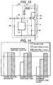
- Fig. 13 is a circuitry showing an ignitor unit structure of an ignitor case part of an outer case of an ignition apparatus for use in an internal combustion according to the present invention.
- An one-chip ignitor 50 installed on the upper portion of the coil portion, as shown in Fig. 13, comprises an insulation type bipolar transistor (hereinafter, "IGBT") 51, a current limitation circuit 52 and an input resistor 53.
- IGBT 51 comprises a main insulation type bipolar transistor (a main-IGBT 54) and a sub insulation type bipolar transistor (a sub-IGBT 55).
- a current detection load 56 is provided between the sub-IGBT 55 and the ground (GND).
- a dual direction polysilicon zener diode 57 is inserted between a gate and a collector of the IGBT 51 and this diode 57 is constituted to have a superior temperature characteristic. Further, this diode 57 clamps the primary voltage with 350-450 V.
- a bleeder resistor 58 is inserted between the input and the ground (GND) and a contact current of an input signal connection part is more than 1 mA. A full connection reliability about a soldering of the terminal, even in case the soldering is Sn soldering, can obtain.
- the copper or an aluminum made metal base for a heat radiation is adhered with a silicon adhesion agent at a lower portion of a heat sink of a side where IGBT 51 joins.
- the IGBT 51 and the terminal are connected with an aluminum wire and are molded by an epoxy resin material and the mold member forms TO-3P type or TO-220 type.
- Fig. 14 is a graph showing a secondary voltage comparison of a respective internal combustion engine having a different thickness of a side core of an ignition apparatus for use in an internal combustion according to the present invention.
- the ignition apparatus can obtain the required necessary secondary voltage.
- the thickness and the length of the side core can vary in accordance with the material or the length of the cylinder head or the cylinder head cover of the plug hole portion of the internal combustion engine.
- the number or the thickness of the magnet which is inserted to one end of the center core or both ends of the center core can vary, as a result the low cost ignition apparatus for use in the internal combustion engine can obtain.
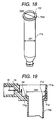
- Fig. 15 is a cross-sectional view showing a state where one embodiment of the ignition apparatus for used in the internal combustion engine is mounted on the internal combustion engine.
- One embodiment of the cylindrical form ignition apparatus 70 for use in the internal combustion engine according to the present invention, as shown in Fig. 15, is mounted on the internal combustion engine.
- the ignition apparatus 70 has an outer case (a reception portion) 71 and a side core 72.
- the outer case 71 comprises an ignitor case part 71a (an ignitor reception portion) and a coil case part 71b (a coil reception portion).
- the internal combustion engine has a cylinder head 73 and a cylinder head cover 74.
- An ignition plug 76 projects and is fixed toward a combustion chamber of the internal combustion engine.
- the ignition apparatus 70 for use in the internal combustion engine is fixed to the cylinder head cover 74 by an installation bolt 80 through an installation portion 71h which is provided on the ignitor case part 71a.
- the coil case part 71b of the ignition apparatus 70 for use in the internal combustion engine is inserted in a plug hole portion 75.
- This plug hole portion 75 is drilled on the cylinder head 73 and the cylinder head cover 74 which easily receive a thermal energy generated in the combustion chamber.
- the coil case part 71b requires a high heat resistance property such as about 710 °C.
- a hole diameter and a hole depth of the plug hole portion 75 to which the coil case part 71b is inserted are standardized at a predetermined rule with a predetermined kind of the internal combustion engine.
- Fig. 16 is an oblique view showing one embodiment of an ignitor case part and a coil case part of an ignition apparatus for use in an internal combustion engine according to the present invention
- Fig. 17 is an oblique view showing one embodiment of an ignitor case of an ignition apparatus for use in an internal combustion engine according to the present invention
- Fig. 18 is an oblique showing one embodiment of a coil case of an ignition apparatus for use in an internal combustion engine according to the present invention.
- the ignitor case part 71a served as a connector 79 is formed by using PBT resin material from aspects of a shock strength and of an assurance of a size dimension accuracy required as the connector 79.
- the connector 79 served as the ignitor case part 71a has various embodiments to correspond with a different specification of the other connector, and various kinds of the ignitor case part 71a are manufactured.
- the connector 79 Since the connector 79 which fits into the other connector has a complicated form, the connector 79 is manufactured using a slide molding processing. Accordingly, to manufacture the ignitor case part 71a served as the connector 79, the ignitor case part 71a requires a material characteristic having an excellent molding property.
- the outer case part 71b comprises the independent and individual ignitor case part 71a and the independent and individual coil case part 71b. Further, the ignitor case part 71a has a combination portion (namely, a fitting-into portion) with the coil case 71b to integrally form the ignitor case part 71a and the coil case part 71b.
- a step portion 71c for preventing a slip off and a projection portion 71e for preventing a rotation stop and for determining a position are provided on the above stated combination portion. Further, a portion for receiving an ignitor case 78 etc. as the ignitor case part 71a forms a cup (inside box) form.
- the coil case part 71b is inserted in the standardized plug hole portion 75 as stated in above.
- the coil case part 71b is formed using PPS resin material from an aspect of a heat resistance property etc..
- the coil case part 71b can form using a mixture resin material in which a denatured polyphenylene oxide resin material ("denatured PPO" or “denatured PPO resin material) being as a composition agent, for example 20 %, is blended to PPS resin material.
- a denatured polyphenylene oxide resin material (“denatured PPO” or “denatured PPO resin material) being as a composition agent, for example 20 %
- the combination portion (namely, the fitting-into portion) is provided on the ignitor case part 71a to integrate the coil case part 71b.
- a step portion 71e for preventing a slip off and a notch portion 71f for preventing a rotation stop and for determining a position are provided on the above stated combination portion.
- an appearance size dimension of the coil case part 71b (for example, diameter D20 of the step portion 71d, a diameter d21 and a whole length of the ignition apparatus case main body) can unify. Accordingly, a common use of the coil case part 71b can attain.
- the diameter D20 of the step portion 71d is the same size dimension of the dimension D20 of the step portion 71c as shown in Fig. 17.
- the diameter D20 of the step portion 71c is the same diameter of the ignitor case part 71a which is manufactured by a different form to correspond with the other connector having a different specification.
- the diameter D20 of the step portion 71c unify to utilize the standardization of the plug hole 75.
- Fig. 19 is a cross-sectional view showing a state in case where at the combination portion of the coil case part and the ignitor case part, one embodiment of both the coil case part and the ignitor case part are integrally combined at the combination portion according to the present invention.
- the outer case 71 comprised of the ignitor case part 71a and the coil case part 71b has two parts to correspond to the difference in the environment condition subjected to actually mount and the various kinds of the connector specification to subjected to require.
- the ignitor case part 71a and the coil case part 71b should integrally combine with at the fitting-into portion.
- the ignitor case part 71a and the coil case part 71b are combined with at the fitting-into portion.
- the combination portion namely, the fitting-into portion
- the ignitor case part 71a and the coil case part 71b are fitted into and integrally combined with at the combination portion.
- an adhesive agent 82 is coated on V form groove 71g which is provided on the combination portion.
- the combination portion is combined using the adhesion processing, namely the combination portion is joined.
- the projection portion 71e and the notch portion 71f are meshed with and then the rotation direction fixes.
- the outer case 71 according to the embodiment of the ignition apparatus comprises the independent and individual ignitor case part 71a and the independent and individual coil case part 71b.
- the above stated ignitor case part 71a is formed with various forms to correspond to the other connector having the different specification.
- the above stated coil case part 71b has the standardized outer appearance (the diameter and the whole length) which corresponds to the standardized plug hole portion 75.
- the ignitor case part 71a and the coil case part 71b are integrally combined with at the combination portion.
- the rectangular angle degree between the axial direction of the coil case part 71b (namely, the hole axial direction of the plug hole portion 75) and the connection direction of the connector 79 (a right angle against the hole axial direction of the plug hole portion 75) and also the size dimension accuracy of a distance between an axial center of the coil case part 71b and a center of an installation portion 71h which is provided on the ignitor case part 71a can secure.
- the combination face of both step portions 71c and 71d is formed to have a contact face which is vertical with the axial direction of a longitudinal direction of the coil case part 71b (namely, the hole axial direction of the plug hole portion 75) and a contact face which is concentrically with an axial center of the coil case part 71b. Accordingly, in the combination portion, both step portions 71c and 71d are fitted into and strongly joined with no aberration.
- Table 1 is a table which is putted in order the material for use in the coil case part 71b and the material for use in the ignitor case part 71a served as the connector 79 by estimating the requirement characteristic of the coil case part 71b and the ignitor case part 71a.
- the required characteristics of the coil case part 71b which is inserted in the plug hole portion 75 for receiving the coil unit are mainly the heat resistance characteristic and the voltage withstanding characteristic.
- the required characteristics of the ignitor case part 71a which receives the ignitor unit 78 and has an important function as the connector 79 are mainly the shock strength and the chemical-proof characteristic.
- each of the materials of the ignitor case part 71a and the coil case part 71b being the outer case 71 has respectively the different required characteristic.
- the material for satisfying the required characteristics of the connector 79 is PBT resin material, for example.
- the material for satisfying the required characteristic of the coil case part 71b is PPS resin material or a mixture resin material of PPS and the denatured PPO, for example.
- the thermal stress under -40 °C and 130 °C which is equivalence of the temperature environment condition of the internal combustion engine, alternatively and repeatedly adds and it is desirable to not generate the peel-off at more than 300 cycles.
- the denatured PPO has a good adhesion property against the insulation epoxy resin material, in generally the denatured PPO is used as the material of a secondary coil of the ignition apparatus.
- the denatured PPO is inferior in the chemical-proof property, the denatured PPO is not suitable for a portion where the substance exposes to the outside atmosphere.
- a sealing rubber member 77 as the sealing body which is inserted to the vicinity of the upper face of the plug hole portion 75 of the internal combustion engine, isolates the environment of the inside and the outside of the plug hole portion 75.
- the above stated sealing rubber member 77 works an important role that it does not expose the coil case part 71b to the outside atmosphere. Accordingly, there is a possibility that the denatured PPO can use to the coil case part 71b.
- the mixture material comprises PPS resin material having the superior heat resistance property, the superior chemical-proof property and the superior voltage withstanding property, and the denatured PPO having the superior adhesion property to the insulation epoxy resin material.
- PPS resin material becomes a base material and 20 % degree denatured PPO is mixed with PPS resin material, therefore the coil case part 71b is made by using the mixture material of the respective characteristic of PPS resin material and the denatured PPO.
- the material for the coil case part 71b it is desirable to mix the base material having the material characteristics of the superior heat resistance property and the superior voltage withstanding property and the mixture agent having the material characteristic of the superior adhesion property to the insulation resin material for insulating the coil part. Further, it is desirable to form the mixture material for utilizing the material characteristic which has the respective resin material.
- the ignition apparatus 70 for use in the internal combustion engine comprises an ignitor part having an electrically connected and adjacently arranged connector 79, and the coil case part 71b, and the reception body 71 (71a and 71b) for receiving the ignitor part and the coil part.
- the reception body 71 has two parts comprised of a coil reception portion 71b and an ignitor reception portion 71a.
- the coil reception portion 71b receives the coil part and is inserted into a standardized plug hole portion 75 of the internal combustion engine.
- the ignitor reception portion 71a receives the ignitor part and is arranged at outside of the plug hole and has the connector 79 which is connected to the other connector having a different specification.
- the coil reception portion 71b and the ignitor reception portion 71a are integrally combined at the combination portion.
- the molding conditions such as a mold parting line direction, an injection gate position and a push-out pin position of the mold form which suits to the respective form, can set appropriately.
- the reception body 71 being as the outer body comprises two parts comprised of the coil case part 71b and the ignitor case part 71a.
- the coil case part 71b serves as the coil reception portion, the coil case part 71b receives mainly the coil part and is inserted into the plug hole portion 75 in which a hole diameter is standardized of the internal combustion engine.
- the ignitor case part 71a serves as the ignitor reception portion and the ignitor case part 71a receives mainly the ignitor part and has the connector 79 which is connected to the other connector having the different specification.
- the coil case part 71b and the ignitor case part 71b are integrally combined at the combination portion.
- the reception body 71 comprises two parts comprised of the coil reception portion 71b inserted in the plug hole portion 75 and the ignitor reception portion 71a positioned at the outside of the plug hole portion 75 by making the boundary of the inside portion and the outside portion of the plug hole 75 of the internal combustion engine in which the environment required specification differs, this environment required specification is determined by the environment where the reception body 71 arranges.
- the coil reception portion 71b and the ignitor reception portion 71a comprise the parts and integrally combined at the combination portion.
- the coil case part 71b for receiving the ignition apparatus main body and the ignitor case part 71a for serving as the connector 79 and for receiving the ignitor unit 78 are separated.
- the coil case part 71b is made by using the synthetic resin material having the superior heat resistance property, the superior voltage withstanding property and the superior adhesion property with the coil insulation resin material.
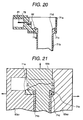
- Fig. 20 is a cross-sectional view showing another embodiment of a state where a coil case part and an ignitor case part are integrally combined at a combination portion of the coil case part and the ignitor case part according to the present invention.
- the coil case part 71b has an extension portion (a development portion) in which the step portion 71d of the coil case part 71b develops and extends along toward a bottom portion of the ignitor case part 71a.
- the development portion of the coil case part 71b having the superior heat resistance property covers the ignitor case part 71a, the heat resistance property of the bottom portion of the ignitor case part 71a which arranges oppositely to the cylinder head cover 74 etc. of the internal combustion engine can improve.
- the ignitor case part 71a which is made by the synthetic resin material having a little inferior heat resistance property, it can obtain a merit for corresponding the severe environment condition wherein the part for facing to the cylinder head cover 74 etc. of the internal combustion engine which is provided the outside of the plug hole portion 75 reaches to 130 °C at maximum temperature.
- the fixture between the coil case part 71b the ignitor case part 71a can carry out by a joining method using the adhesion agent 82, a fixture method for injecting and for fixing by using a fill-up insulation epoxy resin material, a fixture method for manufacturing separately in advance the coil case part 71b and the ignitor case part 71a and after that for integrally molding and for fixing them, etc.. Any method can employ.
- Fig. 21 is a cross-sectional view showing a further embodiment of a state where a coil case part and an ignitor case are integrally combined at a combination portion of the coil case part and the ignitor case part according to the present invention.
- this figure shows a view of a cross-section of the molding state of the both cases according to the method for integrally molding and for fixing stated in above.
- the cross-section has a left sliding metal mold 83a1 and a right sliding metal mold 83a2 for molding a metal mold and a core mold 83b, and an arrow mark shows a movable sliding direction of the respective mold.
- one of the step portion 71c or the step portion 71d is buried against the other side case for integrally molding.
- the buried step portion serves as a role of the pull-out prevention or the rotation stop prevention, and with one tome process of the mold processing, the combination (join) and the pull-out prevention or the rotation stop prevention carries out effectively.
- the coil case part 71b and the ignitor case part 71a for receiving the ignitor unit 78 etc. and serving as the connector 79 are separately formed.
- the cylindrical form ignition apparatus 70 for use in the internal combustion engine for satisfying the respective required characteristic for the connector 79 and the coil case part 71b can obtain.
- the ignitor case part 71a arranges to form an arrangement where the connector 79 extends toward the lateral direction of the ignitor unit 78, namely the connector 79 extends toward the rectangular direction with the hole axial direction of the plug hole portion 75 of the internal combustion engine.
- the whole length in the vertical direction of the ignition apparatus 70 for use in the internal combustion engine becomes short and a space effect can improve.
- the ignition apparatus 70 is connected to a control apparatus having the other part connector having the different specification.
- the other connector has the different connector direction and also the different installation position and this connector having the different form for corresponding to the respective internal combustion engine.
- the above stated correspondence can perform in accordance with the size dimension alternation of only the side of the ignitor case part 71a.
- the common use of the ignitor case part 71a and the coil case part 71b can attain and the standardization in the components can realize, and the low cost ignition apparatus for use in the internal combustion engine can obtain.
- the respective most suitable size dimension and the respective most suitable material can select, as a result the strength and the size dimension of the connector 79, and the durability of the coil part of the ignition apparatus 70 for use in the internal combustion engine can improve.
- the ignition apparatus 70 for use in the internal combustion having the different specification it can correspond according to the alternation of only the ignitor case part 71a, the common use of the ignitor case part 71a with the coil case part 71b can attain.
- the high durability and the high reliability ignition apparatus 70 for use in the internal combustion engine having the short whole length, the high accuracy dimension and the high strength of the connector 79, the superior heat resistance shock property and superior voltage withstanding property can obtain.
- Fig. 22 is a cross-sectional view showing a sealing rubber member structure of an ignition apparatus for use in an internal combustion engine according to the present invention
- Fig. 23 is a cross-sectional view showing a sealing structure having a sealing rubber member of an ignition apparatus for use in an internal combustion engine according to the present invention.
- an ignition apparatus 90 comprises a coil case part 91, a side core 92 having several hemisphere form projection portions 92a, and a sealing rubber member 95.
- the internal combustion engine has a plug tube 93 and a cylinder head cover 94.
- D is an outer diameter of an inner cylindrical portion of the ignition apparatus 90
- D9 is an inner diameter of the cylinder head cover 94
- D5 is an inner diameter of the plug tube 93
- D4 is an outer diameter of the projection portion 92a of the side core 92.
- the sealing rubber member 95 comprises a conical portion 95a having an inner diameter D1, a step portion 95b, an inside cylindrical portion 95c having an inner diameter D2 and an outer diameter D3, a flange portion 95d for forming a radial direction extending face, an upper end portion 95e, a dent portion 95f, and an outside cylindrical portion 95g.
- the step portion 95b makes a dimension size to have D1 ⁇ D ⁇ D2 and the dent portion 95f is provided on the flange portion 95d.
- the sealing rubber member 95 with the above stated structure is inserted under pressure and fixed to the inner cylindrical portion of the ignition apparatus 90.
- sealing rubber member 95 has the step portion 95b where the dimension size is formed to have D1 ⁇ D ⁇ D2, a pressure-in dimensional tolerance at a side of the conical portion 95a can make large.
- the inner diameter D2 of the inside cylindrical portion 95c is larger than the outer diameter D of the inner cylindrical portion of the ignition apparatus 90. Therefore, the sealing rubber member 95 can easily insert to the inner cylindrical portion of the ignition apparatus 90.
- the sealing rubber member 95 in a state where the sealing rubber member 95 is inserted into the inner cylindrical portion of the ignition apparatus 90, the sealing rubber member 95 has the conical portion 95a and a conical tip end portion 95s of the conical portion 95a.
- the conical portion 95a having the conical tip end portion 95s has the tapering form where the outer diameter reduces gradually toward a tip end at the side of an ignition plug.
- an outer periphery face of the outer diameter D3 of the inside cylindrical portion 95c of the sealing rubber member 95 forms a non-contacting state (D3 ⁇ D9) with respect to an inner periphery face of the inner diameter D9 of the plug hole portion in the cylinder head cover 94.
- the sealing rubber member 95 can insert easily to the plug hole.
- the projection portion 92a of the side core 92 forming the inner cylindrical portion has a projection form which projects toward a part or a whole periphery of the outer periphery of the cylindrical portion of the ignition apparatus 90.
- the above stated tip end portion 95s of the conical portion 95a of the sealing rubber member 95 becomes the tip end of the side of the ignition plug of the sealing rubber member 95 which has inserted into the inner cylindrical portion of the ignition apparatus 90.
- the projection portion 92a of the side core 92 positions at a nearer side of the ignition plug than the conical tip end portion 95s of the conical portion 95a of the sealing rubber member 95.
- the outer diameter D4 of the projection portion 92a of the side core 92 has a dimension size relationship of D ⁇ D4 ⁇ D5.
- An outer diameter of the conical tip end portion 95s of the inserted sealing rubber member 95 forms smaller than the outer diameter D4 of the projection portion 92a of the side core 92. Therefore, the turn up of the sealing rubber member 95 can prevent.
- the conical tip end portion 95s of the sealing rubber member 95 positions at a rear portion of the projection portion 92a of the side core 92.
- the projection portion 92a which works a role of the inner cylindrical portion, of the side core 92 can provide on the coil case part 91.
- the sealing rubber member 95 of this embodiment of the ignition apparatus 90 when the ignition apparatus 90 inserts into the plug hole portion, the flange portion 95d for forming the radial direction extending face of the sealing rubber member 95 contacts to a tip end portion 94a of the cylinder head cover 94.
- the sealing structure having the sealing rubber member 95 of the ignition apparatus 90 can form. As a result, the water penetration into the cylinder head cover 94 can prevent.
- a dimensional scatter size occurs about 1 mm degree at the axial direction.
- the flange portion 95d of the sealing rubber member 95 contacts to the tip end portion 94a of the cylinder head cover 94 and is pushed under pressure, the flange portion 95d of the sealing rubber member 95 deforms, accordingly the water penetration etc. can prevent.
- the extension face formed on the above stated flange portion 95d and for extending toward the radial direction indicates a face for extending and expanding toward the radial direction of the inner cylindrical portion of the ignition apparatus 90.
- a necessary extent of the extension face of the flange portion 95d of the sealing rubber member 95 is one where the position slip-off of the plug hole can absorb fully, in other words, where the slip-off toward the radial direction of the tip end portion 94a (the outside cylindrical end portion) of the cylinder head cover 94 can escape.
- the extent is more than one which has a total dimension size of an end portion dimension size of the tip end portion 94a of the cylinder head cover 94 in addition to the maximum slip-off dimension size.
- the tapering form conical portion 95a of the sealing rubber member 95 works a role of the guide member in case where the inner cylindrical portion of the ignition apparatus 90 inserts into the plug hole portion and the plug tube 93. Therefore, an alignment between the cylindrical portion of the ignition apparatus 90 and the plug tube 93 takes precedence.
- the maximum slip-off dimension size must absorb between the plug hole portion formed by the cylinder head cover 94 and the sealing rubber member 95. Therefore, the extension face of the sealing rubber member 95 can absorb the positional slip-off and further can work a role of the sealing function.
- the above sealing structure of the ignition apparatus according to the present invention is exemplified with the ignition apparatus where the internal combustion engine has the plug tube in addition to the cylinder head and the cylinder head cover of the internal combustion engine.
- the above stated sealing structure according to the present invention can employ with the ignition apparatus where the internal combustion engine has the cylinder head and the cylinder head cover but has no plug tube.
Landscapes
- Engineering & Computer Science (AREA)
- Power Engineering (AREA)
- Chemical & Material Sciences (AREA)
- Combustion & Propulsion (AREA)
- Mechanical Engineering (AREA)
- General Engineering & Computer Science (AREA)
- Ignition Installations For Internal Combustion Engines (AREA)
Applications Claiming Priority (6)
| Application Number | Priority Date | Filing Date | Title |
|---|---|---|---|
| JP6409296 | 1996-03-21 | ||
| JP64092/96 | 1996-03-21 | ||
| JP6409296 | 1996-03-21 | ||
| JP10076496A JP3698811B2 (ja) | 1996-04-23 | 1996-04-23 | 内燃機関用点火装置 |
| JP10076496 | 1996-04-23 | ||
| JP100764/96 | 1996-04-23 |
Publications (3)
| Publication Number | Publication Date |
|---|---|
| EP0796993A2 true EP0796993A2 (de) | 1997-09-24 |
| EP0796993A3 EP0796993A3 (de) | 1999-09-01 |
| EP0796993B1 EP0796993B1 (de) | 2003-07-09 |
Family
ID=26405226
Family Applications (1)
| Application Number | Title | Priority Date | Filing Date |
|---|---|---|---|
| EP19970104865 Expired - Lifetime EP0796993B1 (de) | 1996-03-21 | 1997-03-21 | Zündapparat für eine Brennkraftmaschine |
Country Status (3)
| Country | Link |
|---|---|
| EP (1) | EP0796993B1 (de) |
| KR (1) | KR100478171B1 (de) |
| DE (1) | DE69723337T2 (de) |
Cited By (14)
| Publication number | Priority date | Publication date | Assignee | Title |
|---|---|---|---|---|
| WO1999049212A1 (de) * | 1998-03-25 | 1999-09-30 | Robert Bosch Gmbh | Stabspule für zündanlagen |
| WO2000003139A1 (de) * | 1998-07-11 | 2000-01-20 | Audi Ag | Zündspuleneinheit für brennkraftmaschinen |
| FR2785716A1 (fr) * | 1998-10-22 | 2000-05-12 | Denso Corp | Bobine d'allumage comportant un ressort pour etablir la connexion de la bobine avec une bougie d'allumage |
| WO2001006117A1 (de) * | 1999-07-16 | 2001-01-25 | Daimlerchrysler Ag | Elektronisches zündsystem für brennkraftmaschinen |
| EP1108887A2 (de) * | 1999-12-14 | 2001-06-20 | Diamond Electric MFG. Co., Ltd. | Zündspule |
| EP1063425A3 (de) * | 1999-06-22 | 2002-09-25 | Hitachi, Ltd. | Zündvorrichtung für Brennkraftmaschine |
| WO2003038958A1 (de) * | 2001-10-23 | 2003-05-08 | Robert Bosch Gmbh | Verbindungsmittel für zündanlagen von brennkraftmaschinen |
| US6636137B1 (en) | 1996-06-05 | 2003-10-21 | L.H. Carbide Corporation | Ignition coil assembly |
| EP1229241A3 (de) * | 2001-01-31 | 2003-11-26 | Delphi Technologies, Inc. | Zündapparat, der ein elektrisch getrenntes Schild mit integriertem Schuh und Dichtung enthält |
| EP1233176A3 (de) * | 2001-02-14 | 2003-11-26 | Delphi Technologies, Inc. | Zündanordnung mit einem elektrisch getrenntem Schild |
| GB2395230A (en) * | 2002-11-06 | 2004-05-19 | Visteon Global Tech Inc | Ignition coil assembly with spark plug connector |
| EP1557849A2 (de) * | 2004-01-22 | 2005-07-27 | era AG | Zündspule für eine Brennkraftmaschine |
| CN112620368A (zh) * | 2020-12-04 | 2021-04-09 | 中国科学院力学研究所 | 同轴热电偶瞬态热流传感器分层拉拔式加工装置及方法 |
| SE2250534A1 (en) * | 2022-05-02 | 2023-11-03 | Sem Ab | Tubular structure adapted to at least partly enclose a pencil coil for internal combustion engines |
Families Citing this family (2)
| Publication number | Priority date | Publication date | Assignee | Title |
|---|---|---|---|---|
| JP4209400B2 (ja) * | 2005-03-23 | 2009-01-14 | 三菱電機株式会社 | 内燃機関用点火装置 |
| JP4209407B2 (ja) * | 2005-05-19 | 2009-01-14 | 三菱電機株式会社 | 内燃機関用点火装置 |
Citations (8)
| Publication number | Priority date | Publication date | Assignee | Title |
|---|---|---|---|---|
| JPS6233408A (ja) * | 1985-08-06 | 1987-02-13 | Honda Motor Co Ltd | イグニツシヨンコイル一体型プラグキヤツプ |
| FR2624559A3 (fr) * | 1987-12-14 | 1989-06-16 | Magneti Marelli Spa | Bobine d'allumage, en particulier pour moteurs de course |
| US4903675A (en) * | 1989-03-13 | 1990-02-27 | General Motors Corporation | Internal combustion engine ignition apparatus having a primary winding module |
| JPH02228011A (ja) * | 1989-03-01 | 1990-09-11 | Tdk Corp | トランス |
| US5144935A (en) * | 1990-10-03 | 1992-09-08 | Mitsubishi Denki Kabushiki Kaisha | Ignition coil unit for an internal combustion engine |
| JPH05135967A (ja) * | 1991-11-15 | 1993-06-01 | Tdk Corp | トランス |
| US5315982A (en) * | 1990-05-12 | 1994-05-31 | Combustion Electromagnetics, Inc. | High efficiency, high output, compact CD ignition coil |
| EP0738831A2 (de) * | 1995-04-21 | 1996-10-23 | Hitachi, Ltd. | Zündspule für eine innere Brennkraftmaschine |
-
1997
- 1997-03-21 DE DE69723337T patent/DE69723337T2/de not_active Expired - Lifetime
- 1997-03-21 EP EP19970104865 patent/EP0796993B1/de not_active Expired - Lifetime
- 1997-03-21 KR KR1019970009779A patent/KR100478171B1/ko not_active IP Right Cessation
Patent Citations (8)
| Publication number | Priority date | Publication date | Assignee | Title |
|---|---|---|---|---|
| JPS6233408A (ja) * | 1985-08-06 | 1987-02-13 | Honda Motor Co Ltd | イグニツシヨンコイル一体型プラグキヤツプ |
| FR2624559A3 (fr) * | 1987-12-14 | 1989-06-16 | Magneti Marelli Spa | Bobine d'allumage, en particulier pour moteurs de course |
| JPH02228011A (ja) * | 1989-03-01 | 1990-09-11 | Tdk Corp | トランス |
| US4903675A (en) * | 1989-03-13 | 1990-02-27 | General Motors Corporation | Internal combustion engine ignition apparatus having a primary winding module |
| US5315982A (en) * | 1990-05-12 | 1994-05-31 | Combustion Electromagnetics, Inc. | High efficiency, high output, compact CD ignition coil |
| US5144935A (en) * | 1990-10-03 | 1992-09-08 | Mitsubishi Denki Kabushiki Kaisha | Ignition coil unit for an internal combustion engine |
| JPH05135967A (ja) * | 1991-11-15 | 1993-06-01 | Tdk Corp | トランス |
| EP0738831A2 (de) * | 1995-04-21 | 1996-10-23 | Hitachi, Ltd. | Zündspule für eine innere Brennkraftmaschine |
Non-Patent Citations (3)
| Title |
|---|
| PATENT ABSTRACTS OF JAPAN vol. 011, no. 212 (E-522), 9 July 1987 (1987-07-09) & JP 62 033408 A (HONDA MOTOR CO LTD), 13 February 1987 (1987-02-13) * |
| PATENT ABSTRACTS OF JAPAN vol. 014, no. 537 (E-1006), 27 November 1990 (1990-11-27) & JP 02 228011 A (TDK CORP), 11 September 1990 (1990-09-11) * |
| PATENT ABSTRACTS OF JAPAN vol. 017, no. 514 (E-1433), 16 September 1993 (1993-09-16) & JP 05 135967 A (TDK CORP), 1 June 1993 (1993-06-01) * |
Cited By (24)
| Publication number | Priority date | Publication date | Assignee | Title |
|---|---|---|---|---|
| US6636137B1 (en) | 1996-06-05 | 2003-10-21 | L.H. Carbide Corporation | Ignition coil assembly |
| WO1999049212A1 (de) * | 1998-03-25 | 1999-09-30 | Robert Bosch Gmbh | Stabspule für zündanlagen |
| WO2000003139A1 (de) * | 1998-07-11 | 2000-01-20 | Audi Ag | Zündspuleneinheit für brennkraftmaschinen |
| FR2785716A1 (fr) * | 1998-10-22 | 2000-05-12 | Denso Corp | Bobine d'allumage comportant un ressort pour etablir la connexion de la bobine avec une bougie d'allumage |
| US6192873B1 (en) | 1998-10-22 | 2001-02-27 | Denso Corporation | Ignition coil having spring for connecting the same to spark plug |
| EP1063425A3 (de) * | 1999-06-22 | 2002-09-25 | Hitachi, Ltd. | Zündvorrichtung für Brennkraftmaschine |
| WO2001006117A1 (de) * | 1999-07-16 | 2001-01-25 | Daimlerchrysler Ag | Elektronisches zündsystem für brennkraftmaschinen |
| DE19933335A1 (de) * | 1999-07-16 | 2001-01-25 | Telefunken Microelectron | Elektronisches Zündsystem für Brennkraftmaschinen |
| DE19933335C2 (de) * | 1999-07-16 | 2002-11-14 | Volkswagen Ag | Elektronisches Zündsystem für Brennkraftmaschinen |
| EP1108887A2 (de) * | 1999-12-14 | 2001-06-20 | Diamond Electric MFG. Co., Ltd. | Zündspule |
| EP1108887A3 (de) * | 1999-12-14 | 2002-10-16 | Diamond Electric MFG. Co., Ltd. | Zündspule |
| EP1229241A3 (de) * | 2001-01-31 | 2003-11-26 | Delphi Technologies, Inc. | Zündapparat, der ein elektrisch getrenntes Schild mit integriertem Schuh und Dichtung enthält |
| EP1233176A3 (de) * | 2001-02-14 | 2003-11-26 | Delphi Technologies, Inc. | Zündanordnung mit einem elektrisch getrenntem Schild |
| WO2003038958A1 (de) * | 2001-10-23 | 2003-05-08 | Robert Bosch Gmbh | Verbindungsmittel für zündanlagen von brennkraftmaschinen |
| US6932627B2 (en) | 2001-10-23 | 2005-08-23 | Robert Bosch Gmbh | Connecting device for ignition systems of internal combustion engines |
| GB2395230A (en) * | 2002-11-06 | 2004-05-19 | Visteon Global Tech Inc | Ignition coil assembly with spark plug connector |
| GB2395230B (en) * | 2002-11-06 | 2004-09-29 | Visteon Global Tech Inc | Ignition coil assembly with spark plug connector |
| EP1557849A2 (de) * | 2004-01-22 | 2005-07-27 | era AG | Zündspule für eine Brennkraftmaschine |
| DE102004003216B3 (de) * | 2004-01-22 | 2005-08-25 | Era Ag | Zündspule für eine Brennkraftmaschine |
| EP1557849A3 (de) * | 2004-01-22 | 2006-02-01 | era AG | Zündspule für eine Brennkraftmaschine |
| US7152592B2 (en) | 2004-01-22 | 2006-12-26 | Pulse Gmbh | Ignition coil for a combustion engine |
| CN112620368A (zh) * | 2020-12-04 | 2021-04-09 | 中国科学院力学研究所 | 同轴热电偶瞬态热流传感器分层拉拔式加工装置及方法 |
| CN112620368B (zh) * | 2020-12-04 | 2021-09-14 | 中国科学院力学研究所 | 同轴热电偶瞬态热流传感器分层拉拔式加工装置及方法 |
| SE2250534A1 (en) * | 2022-05-02 | 2023-11-03 | Sem Ab | Tubular structure adapted to at least partly enclose a pencil coil for internal combustion engines |
Also Published As
| Publication number | Publication date |
|---|---|
| EP0796993A3 (de) | 1999-09-01 |
| EP0796993B1 (de) | 2003-07-09 |
| KR100478171B1 (ko) | 2005-08-01 |
| DE69723337D1 (de) | 2003-08-14 |
| KR970066077A (ko) | 1997-10-13 |
| DE69723337T2 (de) | 2004-04-15 |
Similar Documents
| Publication | Publication Date | Title |
|---|---|---|
| EP0796993A2 (de) | Zündapparat für eine Brennkraftmaschine | |
| EP1878910B1 (de) | Zündspule zur Verwendung in einem Motor | |
| EP1426985B1 (de) | Stiftförmige Zündspule mit verbesserter Struktur zur Vermeidung von Rissen oder dielektrischer Entladung | |
| EP1026394B1 (de) | Zündspule für Brennkraftmaschine | |
| US6308696B1 (en) | Ignition apparatus for use in internal combustion engine | |
| US6995644B2 (en) | Stick-type ignition coil having improved structure against crack or dielectric discharge | |
| US20020067233A1 (en) | Ignition coil for an internal combustion engine | |
| US6216679B1 (en) | Ignition coil for an internal combustion engine | |
| US6724289B2 (en) | Ignition apparatus having feature for shielding the HV terminal | |
| US7228853B1 (en) | Ignition apparatus having conductive plastic ignition terminal and field smoother | |
| US6810868B2 (en) | Ignition coil for internal combustion engine | |
| US6237578B1 (en) | Ignition coil for use in internal combustion engine | |
| US20030070665A1 (en) | Pencil ignition coil having retention and tactile feel insertion features | |
| JPH1012466A (ja) | 内燃機関用点火装置 | |
| JP3561121B2 (ja) | 内燃機関用点火コイル | |
| US20030037745A1 (en) | Connection of wire to printed circuit board (PCB) | |
| US7004155B2 (en) | Ignition apparatus for internal combustion engine | |
| EP1229619A2 (de) | Zündspule mit Abwicklungsschutz der Zündspulenprimärwicklung | |
| US20040113735A1 (en) | Ignition coil device | |
| US20020101701A1 (en) | Ignition apparatus having an electrically floating shield with integrated boot and seal | |
| JPH11230015A (ja) | 内燃機関用点火コイル | |
| US20030230293A1 (en) | Ignition apparatus for an internal combustion engine and a manufacturing method therefor | |
| EP1589546A1 (de) | Zündspule mit verbessertem Widerstand gegen thermische Spannungen | |
| JP2001244133A (ja) | 内燃機関用円筒型点火装置 | |
| JPH09289120A (ja) | 内燃機関用点火装置 |
Legal Events
| Date | Code | Title | Description |
|---|---|---|---|
| PUAI | Public reference made under article 153(3) epc to a published international application that has entered the european phase |
Free format text: ORIGINAL CODE: 0009012 |
|
| AK | Designated contracting states |
Kind code of ref document: A2 Designated state(s): DE FR GB IT |
|
| PUAL | Search report despatched |
Free format text: ORIGINAL CODE: 0009013 |
|
| AK | Designated contracting states |
Kind code of ref document: A3 Designated state(s): DE FR GB IT |
|
| 17P | Request for examination filed |
Effective date: 19990909 |
|
| 17Q | First examination report despatched |
Effective date: 20020218 |
|
| GRAH | Despatch of communication of intention to grant a patent |
Free format text: ORIGINAL CODE: EPIDOS IGRA |
|
| GRAH | Despatch of communication of intention to grant a patent |
Free format text: ORIGINAL CODE: EPIDOS IGRA |
|
| GRAA | (expected) grant |
Free format text: ORIGINAL CODE: 0009210 |
|
| AK | Designated contracting states |
Designated state(s): DE FR GB IT |
|
| REG | Reference to a national code |
Ref country code: GB Ref legal event code: FG4D |
|
| REF | Corresponds to: |
Ref document number: 69723337 Country of ref document: DE Date of ref document: 20030814 Kind code of ref document: P |
|
| ET | Fr: translation filed | ||
| PLBE | No opposition filed within time limit |
Free format text: ORIGINAL CODE: 0009261 |
|
| STAA | Information on the status of an ep patent application or granted ep patent |
Free format text: STATUS: NO OPPOSITION FILED WITHIN TIME LIMIT |
|
| 26N | No opposition filed |
Effective date: 20040414 |
|
| PGFP | Annual fee paid to national office [announced via postgrant information from national office to epo] |
Ref country code: IT Payment date: 20080129 Year of fee payment: 12 Ref country code: GB Payment date: 20080314 Year of fee payment: 12 |
|
| PGFP | Annual fee paid to national office [announced via postgrant information from national office to epo] |
Ref country code: FR Payment date: 20080225 Year of fee payment: 12 |
|
| GBPC | Gb: european patent ceased through non-payment of renewal fee |
Effective date: 20090321 |
|
| REG | Reference to a national code |
Ref country code: FR Ref legal event code: ST Effective date: 20091130 |
|
| PG25 | Lapsed in a contracting state [announced via postgrant information from national office to epo] |
Ref country code: GB Free format text: LAPSE BECAUSE OF NON-PAYMENT OF DUE FEES Effective date: 20090321 Ref country code: FR Free format text: LAPSE BECAUSE OF NON-PAYMENT OF DUE FEES Effective date: 20091123 |
|
| PG25 | Lapsed in a contracting state [announced via postgrant information from national office to epo] |
Ref country code: IT Free format text: LAPSE BECAUSE OF NON-PAYMENT OF DUE FEES Effective date: 20090321 |
|
| PGFP | Annual fee paid to national office [announced via postgrant information from national office to epo] |
Ref country code: DE Payment date: 20160315 Year of fee payment: 20 |
|
| REG | Reference to a national code |
Ref country code: DE Ref legal event code: R071 Ref document number: 69723337 Country of ref document: DE |