EP0796788B1 - Station einer Verpackungslinie zum Umfalten einer Fahne eines Beutels - Google Patents
Station einer Verpackungslinie zum Umfalten einer Fahne eines Beutels Download PDFInfo
- Publication number
- EP0796788B1 EP0796788B1 EP97103402A EP97103402A EP0796788B1 EP 0796788 B1 EP0796788 B1 EP 0796788B1 EP 97103402 A EP97103402 A EP 97103402A EP 97103402 A EP97103402 A EP 97103402A EP 0796788 B1 EP0796788 B1 EP 0796788B1
- Authority
- EP
- European Patent Office
- Prior art keywords
- flag
- cam
- folding
- flap
- retention means
- Prior art date
- Legal status (The legal status is an assumption and is not a legal conclusion. Google has not performed a legal analysis and makes no representation as to the accuracy of the status listed.)
- Expired - Lifetime
Links
- 238000004806 packaging method and process Methods 0.000 title claims description 5
- 238000003825 pressing Methods 0.000 claims description 2
- 230000014759 maintenance of location Effects 0.000 claims 5
- 238000000034 method Methods 0.000 description 4
- 241001295925 Gegenes Species 0.000 description 2
- 239000000853 adhesive Substances 0.000 description 2
- 230000001070 adhesive effect Effects 0.000 description 2
- 239000004831 Hot glue Substances 0.000 description 1
- 239000002390 adhesive tape Substances 0.000 description 1
- 230000002349 favourable effect Effects 0.000 description 1
- 239000003292 glue Substances 0.000 description 1
- 239000000463 material Substances 0.000 description 1
- 238000005096 rolling process Methods 0.000 description 1
- 229920001169 thermoplastic Polymers 0.000 description 1
- 239000004416 thermosoftening plastic Substances 0.000 description 1
- 238000003466 welding Methods 0.000 description 1
Images



Classifications
-
- B—PERFORMING OPERATIONS; TRANSPORTING
- B65—CONVEYING; PACKING; STORING; HANDLING THIN OR FILAMENTARY MATERIAL
- B65B—MACHINES, APPARATUS OR DEVICES FOR, OR METHODS OF, PACKAGING ARTICLES OR MATERIALS; UNPACKING
- B65B7/00—Closing containers or receptacles after filling
- B65B7/02—Closing containers or receptacles deformed by, or taking-up shape, of, contents, e.g. bags, sacks
Definitions
- the invention relates to a station of a packaging line for folding a flag a bag, e.g. Tubular bag, along a forming line and to Squeeze the folded flag, with one against the flag and against a resistance movable folding element, and with a feed device for Feed the bag to the folding element.
- a station of a packaging line for folding a flag a bag, e.g. Tubular bag, along a forming line and to Squeeze the folded flag, with one against the flag and against a resistance movable folding element, and with a feed device for Feed the bag to the folding element.
- the bag can be welded on the head side using welding jaws.
- the upward-facing flag of the bag can be folded down. By folding over the height of the flag e.g. halved.
- the folded flag can be fixed in its folded position using glue, adhesive tape or adhesive label become. Folding can also take place with the flag open and unwelded.
- EP 0 476 273 A1 describes a station according to the preamble of claim 1 known. At this station the drive mechanism includes two vertically mutually movable slides for moving a folding element.
- the known prior art has the disadvantage that the movement of the Folding element can not be changed in a mechanically simple manner.
- the invention is based on the object of eliminating this disadvantage.
- the folding element is vertical in two by means of a drive mechanism mutually driven directions, and it's one against the forming line the flag movable holding element having a rectilinear forming edge intended.
- Forming line is generated because the flag first between the resistance and the Holding element is clamped, whereby it is precisely fixed, then the upper Part of the flag folded over on the straight forming edge, whereby the forming line becomes straight, and finally the holding element is off the flag removed, and the folding element presses due to its practicable in one plane Move the part of the flag above the forming line against the lower one Part of the flag and against the resistance.
- the two perpendicular to each other Standing directions of the drive mechanism describe the plane of movement of the folding element.
- the folding element can be used during the Flipping away from the resistance and then back to the resistance to be moved to first create the forming line and then the flag parts to press against each other.
- Pinching and holding the lower part of the flag and folding the upper part of the flag against the rectilinear forming edge of the Holding element is used for the exact generation of the forming line. Removing the Holding element from the flag and the movement of the folding element against the lower part of the flag and against the resistance is used to close the folded flag stabilize.
- the stabilized, folded flag could then by means of a Adhesive labels can be fixed.
- the drive mechanism of the folding element contains a cam. So can a movement cycle of the folding element for folding a flag by one Revolution of the cam can be realized. For a change of one Only the cam disc has to be replaced.
- the movement path is composed of a large number of straight path sections, can the trajectory in a simplified constructive manner or Programming can be specified.
- the direction of action of the folding element is also involved against the flag always constant for a time interval.
- a nine-shaped trajectory is optimally used to fold the flags, because that free end of the trajectory the process of squeezing the folded Describes flag against resistance. After the pressing process is finished the folding element again along the free end of the movement path from Resistance removed to with the closed part of the nine-shaped Movement station to get into a starting position for a new flag transfer.
- the folding element is rigid with a slide is connected, a cam roller is rotatably attached to the carriage, and the cam roller rolls along the curve of the cam.
- the movement of the slide corresponds to that Movement of the folding element.
- the carriage can be from one of the folding element more distant cam roller can be moved. The movement is transmitted very reliable.
- A serves the purpose of securely engaging the cam roller on the cam Tension spring between the bracket and the slide.
- the tension spring ensures one Minimum pressure with which the cam roller acts against the cam disc. Is the mainspring provided in the area of the cam roller, the pressure generation is more independent of possibly occurring tilting moments.
- The is suitable as a simple and reliable drive for the cam disc Crank drive. It can take the cam regardless of the position of the bracket are driven by the crank drive and the cam roller is always in contact with the cam.
- a swiveling holding element can easily be towards and away from the flag be removed. If the holding element acts against the flag at half the height of the flag, then the flag is folded halfway down and the folded one Flag has a minimal height.
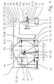
- flags 2 are folded over by bags 3 and compressed ( Figure 1). Each time a flag 2, which previously with Hot glue was sprayed on one side, halved in terms of its remaining height and because of the then double flag position. The bags 3 arrive in cycles station 1.
- At station 1 is a movable against the flag 2 and against a resistance Folding element 5 is provided.
- a feed device 6 in the form of a cup belt 7 carries a new bag 3 to the station 1 per work cycle such that the Flag 2 of the bag 3 is applied to the resistor 4.
- the folding element 5 becomes vertical in two by means of a drive mechanism 16 directions 8, 9 driven to each other.
- a holding element 11 is movable.
- the holding element 11 has a straight line Forming edge 12.
- the folding of the flag 2 happens during the use of the rectilinear forming edge 12.
- the holding element 11 is first against the Forming line 10 and pressed against the resistor 4.
- the forming edge works 12 halfway up the flag 13 against the flag 2. Then folds Folding element 5 initially with the holding element 11 holding the flag 2 unchanged the forming line 10.
- the drive mechanism 16 of station 1 contains a cam disc 17. Die Cam 17 is designed such that it covers the entire, with a motor 43 equipped drive mechanism 16 to a nine-shaped movement path 18 leads for the folding element 5.
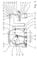
- the movement path 18 is composed of a Large number of straight track sections 19, 20, 21, 22, 23, 24, 25 together. From the position 1, the path section 25 of a reference point 26 started. Correspondingly, the web section 20 is illustrated in FIG. 2, in FIG. 3 the end of the track section 19, in Figure 4 the next end after passing through again of the track section 19 and part of the track section 20. In FIGS. 4 to 6, the track sections 21 and 22 are run through.
- the holding element 11 describes a curved, corresponding to its pivoting Lane 27.
- the folding element 5 is rigidly connected to a carriage 30. With the sled 30 a cam roller 31 is also rotatably connected. The cam roller 31 rolls along the Curve 32 of the cam disk 17. The cam disk 17 is over its axis of rotation 33 rotatably connected to a slidable bracket 34.
- the carriage 30 is in one Plane along mutually perpendicular linear guides 35, 35 in directions 8, 9 or a combination of these directions 8, 9 displaceable.
- crank drive 38 is provided as the drive 37 of the holder 34.
- a Crank rod 39 of crank drive 38 is displaceable via a joint 40 Bracket 34 and connected to cam 17 via a further joint 41.
Landscapes
- Engineering & Computer Science (AREA)
- Mechanical Engineering (AREA)
- Closing Of Containers (AREA)
- Making Paper Articles (AREA)
- Folding Of Thin Sheet-Like Materials, Special Discharging Devices, And Others (AREA)
- Auxiliary Devices For And Details Of Packaging Control (AREA)
Description
- Figur 1
- in einer Seitenansicht eine Station einer Verpackungslinie, wobei an der Station ein Beutel mit einer hochstehenden Fahne angelangt ist, mit einem auf halber Fahnenhöhe gegen die Fahne und einen Widerstand drückendem Halteelement, sowie einem Umlegeelement zum Umlegen der Fahne, welches starr mit einem Schlitten verbunden ist, der eine entlang einer Kurvenscheibe abrollende Kurvenrolle aufweist;
- Figur 2
- in einer Seitenansicht den Gegenstand der Figur 1, jedoch zu einem späteren Zeitpunkt, mit weggeschwenktem Halteelement und vom Umlegeelement umgelegtem oberen Teil der Fahne, und mit nach unten verschobener Halterung, auf der die Kurvenscheibe drehbar befestigt ist;
- Figur 3
- in einer Seitenansicht den Gegenstand der Figur 2, jedoch zu einem späteren Zeitpunkt, mit umgelegter und vom Umlegeelement gegen den Widerstand gedrückter Fahne;
- Figur 4
- in einer Seitenansicht den Gegenstand der Figur 3, jedoch zu einem späteren Zeitpunkt, mit von der Fahne entferntem Umlegeelement;
- Figur 5
- in einer Seitenansicht den Gegenstand der Figur 4, jedoch zu einem späteren Zeitpunkt, mit weiter von der Fahne entferntem Umlegeelement, sowie
- Figur 6
- in einer Seitenansicht den Gegenstand der Figur 5, jedoch zu einem späteren Zeitpunkt und mit einer weiteren Positionierung des Umlegeelementes.
- 1
- Station
- 2
- Fahne
- 3
- Beutel
- 4
- Widerstand
- 5
- Umlegeelement
- 6
- Zuführeinrichtung
- 7
- Becherband
- 8, 9
- Richtung
- 10
- Umformlinie
- 11
- Halteelement
- 12
- Umformkante
- 13
- halbe Fahnenhöhe
- 14
- oberes Teil
- 15
- unteres Teil
- 16
- Antriebsmechanismus
- 17
- Kurvenscheibe
- 18
- Bewegungsbahn
- 19, 20, 21, 22 23, 24, 25
- gerader Bahnabschnitt
- 26
- Bezugspunkt
- 27
- gekrümmte Bahn
- 28
- freies Ende
- 29
- geschlossener Teil
- 30
- Schlitten
- 31
- Kurvenrolle
- 32
- Kurve
- 33
- Drehachse
- 34
- Halterung
- 35, 36
- Linearführung
- 37
- Antrieb
- 38
- Kurbelantrieb
- 39
- Kurbelstange
- 40, 41
- Gelenk
- 42
- Zugfeder
Claims (3)
- Station einer Verpackungslinie zum Umfalten einer Fahne (2) eines Beutels (3) entlang einer Umformlinie (10) der Fahne (2) und zum Zusammendrücken der umgefalteten Fahne (2), mit einem gegen die Fahne (2) und gegen einen Widerstand (4) beweglichen Umlegeelement (5), und mit einer Zuführeinrichtung (6) zum Zuführen des Beutels (3) an das Umlegeelement (5), wobei das Umlegeelement (5) über einen Antriebsmechanismus (16) in zwei senkrecht zueinander stehende Richtungen (8, 9) angetrieben wird, und ein gegen die Umformlinie (10) der Fahne (2) bewegliches, eine geradlinige Umformkante (12) aufweisendes Halteelement (11) vorgesehen ist, dadurch gekennzeichnet, dass der Antriebsmechanismus (16) eine um eine Drehachse (33) drehbare Kurvenscheibe (17) enthält, dass das Umlegeelement starr mit einem Schlitten (30) verbunden ist, dass eine Kurvenrolle (31) drehbar mit dem Schlitten (30) verbunden ist, dass die Kurvenrolle (31) entlang der Kurve (32) der Kurvenscheibe (17) rollt, dass der Schlitten (30) über eine erste Linearführung (36) mit einer Halterung (34) verschiebbar verbunden ist, wobei die Halterung (34) in einer Ebene entlang, einer zweiten Linearführung (35) verschiebbar ist, wobei die Linearführungen (35, 36) einen rechten Winkel zueinander beschreiben, dass ein Kurbelantrieb (38) als Antrieb (37) der Halterung (34) vorgesehen ist, und dass eine Kurbelstange (39) des Kurbelantriebs (38) über ein Gelenk (40) mit der verschiebbaren Halterung (34) und über ein weiteres Gelenk (41) mit der Kurvenscheibe (17) verbunden ist.
- Station nach Anspruch 1, dadurch gekennzeichnet, dass eine Zugfeder (42) zwischen der verschiebbaren Halterung (34) und dem Schlitten (30) vorgesehen ist.
- Station nach Anspruch 1, dadurch gekennzeichnet, dass die Zugfeder (42) im Bereich der Kurvenrolle (31) vorgesehen ist.
Applications Claiming Priority (3)
| Application Number | Priority Date | Filing Date | Title |
|---|---|---|---|
| DE19611156 | 1996-03-21 | ||
| DE19611156A DE19611156A1 (de) | 1996-03-21 | 1996-03-21 | Station einer Verpackungslinie zum Umfalten einer Fahne eines Beutels |
| US08/876,403 US5797241A (en) | 1996-03-21 | 1997-06-16 | Station in a packaging line for folding a flap of a bag |
Publications (3)
| Publication Number | Publication Date |
|---|---|
| EP0796788A2 EP0796788A2 (de) | 1997-09-24 |
| EP0796788A3 EP0796788A3 (de) | 1997-11-26 |
| EP0796788B1 true EP0796788B1 (de) | 2002-10-23 |
Family
ID=26024005
Family Applications (1)
| Application Number | Title | Priority Date | Filing Date |
|---|---|---|---|
| EP97103402A Expired - Lifetime EP0796788B1 (de) | 1996-03-21 | 1997-03-01 | Station einer Verpackungslinie zum Umfalten einer Fahne eines Beutels |
Country Status (3)
| Country | Link |
|---|---|
| US (1) | US5797241A (de) |
| EP (1) | EP0796788B1 (de) |
| DE (1) | DE19611156A1 (de) |
Families Citing this family (2)
| Publication number | Priority date | Publication date | Assignee | Title |
|---|---|---|---|---|
| DE19746378A1 (de) * | 1997-10-21 | 1999-04-22 | Rovema Gmbh | Vorrichtung zum Falten einer Fahne eines Beutels |
| CN113059858A (zh) * | 2021-03-18 | 2021-07-02 | 安楠 | 一种复合塑料编织袋加工系统及制作加工方法 |
Family Cites Families (11)
| Publication number | Priority date | Publication date | Assignee | Title |
|---|---|---|---|---|
| US1544315A (en) * | 1923-03-01 | 1925-06-30 | Thomas L Harrison | Collapsible-tube-closing machine |
| US1979496A (en) * | 1932-08-26 | 1934-11-06 | Firm Fr Hesser Maschinenfabrik | Device for closing filled bags |
| US2273585A (en) * | 1940-05-22 | 1942-02-17 | Cons Packaging Machinery Corp | Apparatus for forming siftproof bag closures |
| US2571103A (en) * | 1948-10-29 | 1951-10-16 | Bemis Bro Bag Co | Bag sealing machine |
| US2533642A (en) * | 1949-01-19 | 1950-12-12 | Pneumatic Scale Corp | Lined container forming machine |
| US3097576A (en) * | 1961-09-18 | 1963-07-16 | Atlas General Ind Inc | Devices for forming hinge cover folding boxes |
| US4569184A (en) * | 1981-11-06 | 1986-02-11 | Anderson Bros Apv Inc | Machine for erecting, filling and closing cartons |
| JPS6216302A (ja) * | 1985-07-08 | 1987-01-24 | 三菱重工業株式会社 | 包装機の箱詰成形装置 |
| DE69122587T2 (de) * | 1990-07-27 | 1997-02-13 | Fuji Photo Film Co Ltd | Vorrichtung zum Füllen und Versiegeln von Beuteln |
| US5324250A (en) * | 1992-11-25 | 1994-06-28 | Tetra Laval Holdings & Finance S.A. | Method and apparatus for folding bottom panels of a carton blank |
| US5613933A (en) * | 1994-02-04 | 1997-03-25 | Advanced Container Corporation | Shipping and display box former |
-
1996
- 1996-03-21 DE DE19611156A patent/DE19611156A1/de not_active Withdrawn
-
1997
- 1997-03-01 EP EP97103402A patent/EP0796788B1/de not_active Expired - Lifetime
- 1997-06-16 US US08/876,403 patent/US5797241A/en not_active Expired - Lifetime
Also Published As
| Publication number | Publication date |
|---|---|
| DE19611156A1 (de) | 1997-09-25 |
| EP0796788A2 (de) | 1997-09-24 |
| EP0796788A3 (de) | 1997-11-26 |
| US5797241A (en) | 1998-08-25 |
Similar Documents
| Publication | Publication Date | Title |
|---|---|---|
| DE69701057T2 (de) | Verfahren und Vorrichtung zum Öffnen und Füllen von Mehrkammerbeuteln und dabei erzeugte Beutel | |
| DE4218810C2 (de) | Schlauchbeutelmaschine zum kontinuierlichen Herstellung von mit Seitenfalten vesehenen Packungen | |
| DE69306916T2 (de) | Automatische Maschine zum Herstellen, Füllen und Verschliessen von Säcken oder dergleichen | |
| DE2536973C3 (de) | Vorrichtung zum Schließen der Bodenfaltung von Verpackungen | |
| DE2716743A1 (de) | Druckvorrichtung | |
| DE69300459T2 (de) | Vorrichtung zur Bildung eines Rohres. | |
| DE2125228A1 (en) | Tube welding appts - with folders aligned the welding jaws | |
| DE4206968A1 (de) | Verfahren und vorrichtung zum automatischen einschlagen quadratischer oder rechteckiger stapel aus papiererzeugnissen | |
| DE69501085T2 (de) | Verfahren und Vorrichtung zum Überführen von Laschen an eine laufende Materialbahn | |
| DE69702563T2 (de) | Verfahren zur Befestigung von Verschlüssen an Beuteln während ihrer kontinuierlichen Herstellung | |
| DE19611156A1 (de) | Station einer Verpackungslinie zum Umfalten einer Fahne eines Beutels | |
| DE1761880B1 (de) | Verfahren und Vorrichtung zum Aufbringen von Papier- oder Kunststofftraggriffen auf eine Werkstoffbahn | |
| DE69619000T2 (de) | Gerät zum Verbinden von Warenbahnen | |
| EP0161449B1 (de) | Vorrichtung zum Verschliessen gefüllter Säcke | |
| EP0768242A1 (de) | Verschliessvorrichtung für offene, gefüllte Beutel | |
| CH406953A (de) | Packstoffvorzugsvorrichtung an Verpackungsmaschinen | |
| DE3026038C2 (de) | Vorrichtung zum Anbringen von Querschweiß- oder Querschweißtrennähten an eine Bahn aus thermoplastischem oder heißsiegelfähigem Material | |
| DE19929018A1 (de) | Vorrichtung zum Verpacken | |
| DE2821444C2 (de) | Vorrichtung zum Falten der flachgelegten EinfüUöffnungen von Großsäcken auf sich selbst und zu deren Verschließen durch Verschlußstreifen | |
| DE19538166C2 (de) | Vorrichtung und Verfahren zum kontinuierlichen Beleimen von Faltschachtelzuschnitten | |
| DE293315C (de) | ||
| DE1786472A1 (de) | Verfahren und Vorrichtung zum Etikettieren von Aufgussbeuteln | |
| DE19808776A1 (de) | Vorrichtung zum Bearbeiten von vorbeibewegten Gegenständen | |
| DE2621494C2 (de) | Vorrichtung zum Herstellen und Aufbringen von Ventilschläuchen auf Ventilsäcke | |
| DE1511683C3 (de) | Vorrichtung zum Schließen von Verpackungsbeuteln |
Legal Events
| Date | Code | Title | Description |
|---|---|---|---|
| PUAI | Public reference made under article 153(3) epc to a published international application that has entered the european phase |
Free format text: ORIGINAL CODE: 0009012 |
|
| 17P | Request for examination filed |
Effective date: 19970326 |
|
| AK | Designated contracting states |
Kind code of ref document: A2 Designated state(s): CH DE IT LI |
|
| PUAL | Search report despatched |
Free format text: ORIGINAL CODE: 0009013 |
|
| RHK1 | Main classification (correction) |
Ipc: B65B 7/08 |
|
| AK | Designated contracting states |
Kind code of ref document: A3 Designated state(s): CH DE IT LI |
|
| 17Q | First examination report despatched |
Effective date: 20001218 |
|
| GRAG | Despatch of communication of intention to grant |
Free format text: ORIGINAL CODE: EPIDOS AGRA |
|
| GRAG | Despatch of communication of intention to grant |
Free format text: ORIGINAL CODE: EPIDOS AGRA |
|
| GRAH | Despatch of communication of intention to grant a patent |
Free format text: ORIGINAL CODE: EPIDOS IGRA |
|
| GRAH | Despatch of communication of intention to grant a patent |
Free format text: ORIGINAL CODE: EPIDOS IGRA |
|
| GRAA | (expected) grant |
Free format text: ORIGINAL CODE: 0009210 |
|
| AK | Designated contracting states |
Kind code of ref document: B1 Designated state(s): CH DE IT LI |
|
| REG | Reference to a national code |
Ref country code: CH Ref legal event code: EP |
|
| REG | Reference to a national code |
Ref country code: CH Ref legal event code: NV Representative=s name: A. BRAUN, BRAUN, HERITIER, ESCHMANN AG PATENTANWAE |
|
| REF | Corresponds to: |
Ref document number: 59708519 Country of ref document: DE Date of ref document: 20021128 |
|
| PLBE | No opposition filed within time limit |
Free format text: ORIGINAL CODE: 0009261 |
|
| STAA | Information on the status of an ep patent application or granted ep patent |
Free format text: STATUS: NO OPPOSITION FILED WITHIN TIME LIMIT |
|
| 26N | No opposition filed |
Effective date: 20030724 |
|
| PGFP | Annual fee paid to national office [announced via postgrant information from national office to epo] |
Ref country code: IT Payment date: 20060331 Year of fee payment: 10 |
|
| PGFP | Annual fee paid to national office [announced via postgrant information from national office to epo] |
Ref country code: CH Payment date: 20070314 Year of fee payment: 11 |
|
| REG | Reference to a national code |
Ref country code: CH Ref legal event code: PFA Owner name: ROVEMA VERPACKUNGSMASCHINEN GMBH Free format text: ROVEMA VERPACKUNGSMASCHINEN GMBH#INDUSTRIEGEBIET#35463 FERNWALD (DE) -TRANSFER TO- ROVEMA VERPACKUNGSMASCHINEN GMBH#INDUSTRIEGEBIET#35463 FERNWALD (DE) |
|
| REG | Reference to a national code |
Ref country code: CH Ref legal event code: PL |
|
| PG25 | Lapsed in a contracting state [announced via postgrant information from national office to epo] |
Ref country code: LI Free format text: LAPSE BECAUSE OF NON-PAYMENT OF DUE FEES Effective date: 20080331 Ref country code: CH Free format text: LAPSE BECAUSE OF NON-PAYMENT OF DUE FEES Effective date: 20080331 |
|
| PG25 | Lapsed in a contracting state [announced via postgrant information from national office to epo] |
Ref country code: IT Free format text: LAPSE BECAUSE OF NON-PAYMENT OF DUE FEES Effective date: 20070301 |
|
| REG | Reference to a national code |
Ref country code: DE Ref legal event code: R082 Ref document number: 59708519 Country of ref document: DE Representative=s name: ADVOTEC. PATENT- UND RECHTSANWAELTE, DE |
|
| REG | Reference to a national code |
Ref country code: DE Ref legal event code: R082 Ref document number: 59708519 Country of ref document: DE Representative=s name: ADVOTEC. PATENT- UND RECHTSANWAELTE, DE Effective date: 20111012 Ref country code: DE Ref legal event code: R081 Ref document number: 59708519 Country of ref document: DE Owner name: ROVEMA GMBH, DE Free format text: FORMER OWNER: ROVEMA - VERPACKUNGSMASCHINEN GMBH, 35463 FERNWALD, DE Effective date: 20111012 |
|
| PGFP | Annual fee paid to national office [announced via postgrant information from national office to epo] |
Ref country code: DE Payment date: 20140515 Year of fee payment: 18 |
|
| REG | Reference to a national code |
Ref country code: DE Ref legal event code: R119 Ref document number: 59708519 Country of ref document: DE |
|
| PG25 | Lapsed in a contracting state [announced via postgrant information from national office to epo] |
Ref country code: DE Free format text: LAPSE BECAUSE OF NON-PAYMENT OF DUE FEES Effective date: 20151001 |