EP0793974B1 - Implantierbares Elektrostimulationsgerät und Elektrodenleitung - Google Patents
Implantierbares Elektrostimulationsgerät und Elektrodenleitung Download PDFInfo
- Publication number
- EP0793974B1 EP0793974B1 EP97250058A EP97250058A EP0793974B1 EP 0793974 B1 EP0793974 B1 EP 0793974B1 EP 97250058 A EP97250058 A EP 97250058A EP 97250058 A EP97250058 A EP 97250058A EP 0793974 B1 EP0793974 B1 EP 0793974B1
- Authority
- EP
- European Patent Office
- Prior art keywords
- lug
- projection regions
- electrode lead
- contact
- regions
- Prior art date
- Legal status (The legal status is an assumption and is not a legal conclusion. Google has not performed a legal analysis and makes no representation as to the accuracy of the status listed.)
- Expired - Lifetime
Links
- 230000000638 stimulation Effects 0.000 title claims description 3
- 239000000463 material Substances 0.000 claims description 3
- 238000006073 displacement reaction Methods 0.000 claims description 2
- 238000004519 manufacturing process Methods 0.000 claims description 2
- 229910000639 Spring steel Inorganic materials 0.000 claims 1
- 230000015572 biosynthetic process Effects 0.000 claims 1
- 238000010276 construction Methods 0.000 claims 1
- 230000000052 comparative effect Effects 0.000 description 4
- 238000003780 insertion Methods 0.000 description 4
- 230000037431 insertion Effects 0.000 description 4
- 238000009413 insulation Methods 0.000 description 4
- 238000011161 development Methods 0.000 description 3
- 230000018109 developmental process Effects 0.000 description 3
- 230000002349 favourable effect Effects 0.000 description 3
- 230000011218 segmentation Effects 0.000 description 3
- 238000013461 design Methods 0.000 description 2
- 239000002184 metal Substances 0.000 description 2
- 230000035515 penetration Effects 0.000 description 2
- 238000007789 sealing Methods 0.000 description 2
- 238000003466 welding Methods 0.000 description 2
- SGOUTOUMITUGNV-UHFFFAOYSA-N CC(C)C1C(C2C)C2C(C)C1 Chemical compound CC(C)C1C(C2C)C2C(C)C1 SGOUTOUMITUGNV-UHFFFAOYSA-N 0.000 description 1
- 241000209035 Ilex Species 0.000 description 1
- 239000011324 bead Substances 0.000 description 1
- 238000005452 bending Methods 0.000 description 1
- 210000001124 body fluid Anatomy 0.000 description 1
- 239000010839 body fluid Substances 0.000 description 1
- 238000004049 embossing Methods 0.000 description 1
- 230000036316 preload Effects 0.000 description 1
- 238000012545 processing Methods 0.000 description 1
- 238000007493 shaping process Methods 0.000 description 1
Images




Classifications
-
- A—HUMAN NECESSITIES
- A61—MEDICAL OR VETERINARY SCIENCE; HYGIENE
- A61N—ELECTROTHERAPY; MAGNETOTHERAPY; RADIATION THERAPY; ULTRASOUND THERAPY
- A61N1/00—Electrotherapy; Circuits therefor
- A61N1/02—Details
- A61N1/04—Electrodes
- A61N1/05—Electrodes for implantation or insertion into the body, e.g. heart electrode
-
- A—HUMAN NECESSITIES
- A61—MEDICAL OR VETERINARY SCIENCE; HYGIENE
- A61N—ELECTROTHERAPY; MAGNETOTHERAPY; RADIATION THERAPY; ULTRASOUND THERAPY
- A61N1/00—Electrotherapy; Circuits therefor
- A61N1/18—Applying electric currents by contact electrodes
- A61N1/32—Applying electric currents by contact electrodes alternating or intermittent currents
- A61N1/36—Applying electric currents by contact electrodes alternating or intermittent currents for stimulation
- A61N1/372—Arrangements in connection with the implantation of stimulators
- A61N1/375—Constructional arrangements, e.g. casings
- A61N1/3752—Details of casing-lead connections
Definitions
- the invention relates to an implantable electrostimulation device, for example a pacemaker or defibrillator, which in the preamble of claim 1 specified type and an electrode line according to the preamble of the claim 7th
- DE-A-3 311 510 describes an arrangement for connecting the proximal end a bipolar lead with a pacemaker known, wherein the electrode lead has a front pin contact and one in the distal direction has ring contact behind it.
- the proximal pin contacts of the Electrode leads are connected to the pacemaker in one introduced hollow cylindrical, so-called end block and there with a Screw fixed in position.
- the stud screw in the end block should on the one hand ensure sufficient electrical contact and, on the other hand, one Protection against undesired axial displacement of the line contact within of the end block, so that the proximal end of the bipolar electrode lead cannot detach from the pacemaker.
- the distal one Direction behind the pin contact provided second, designed as a ring contact
- the electrode lead is connected to a socket for contacting inserted, which has three incisions on its inner surface.
- incisions are under a substantially circularly curved wire a mechanical preload is used so that the ring contact on three points is electrically connected to the wire when the pin contact the electrode lead is in the end block intended for it.
- US-A-4 583 543 discloses an arrangement for connecting a bipolar electrode lead suggested using a pacemaker when connecting a thinner than the originally intended electrode lead in the head part an adapter is provided for the pacemaker.
- the connection between The adapter and electrode lead are made using a frictional connection, which solely by multiple, essentially only point-like contacting arises on a single circumferential line of the contact of the electrode line. Securing against loosening of the connection under an axial load the electrode lead appears to be inadequate.
- EP-A-0 339 877 describes a connection system for a pacemaker known in which two metal cylinders in the head part of the pacemaker with internal spring wires for contacting the connections of the electrode line are provided.
- the protection against loosening of the electrical connection between electrode lead and pacemaker with mechanical Load in the axial direction is also insufficient here, since this is only a Counteracts friction in substantially linear contact areas.
- the object of the invention based, an electrostimulation device of the type mentioned and a to create connectable electrode lead with the electrostimulation device, the are easily and quickly connectable and their connection at the same time a high level of security against axial tension on the electrode line having.
- the invention includes the idea of connecting to the electrical stimulation device and / or on at least one of the contacts on the electrode line plug fixedly attached a plurality of engagement areas to the relative Large-area electrical contact and generation of a positive connection and preferably additionally to provide a frictional connection, whereby one in a high resistance is opposed to the essential axially directed tensile force becomes.
- cam or projection areas are preferably grouped in several parallel to one another and axially Arranged extending planes arranged.
- connection socket To form the radially inward contact and holding means of the connection socket in the head part of the pacemaker is according to a technological Variant of the connection socket a sleeve inserted into the socket provided with bridge-like, elastic projection areas that are special by embossing and bending from a flat, spring properties and preferred high conductivity material is made.
- This sleeve encloses taut elastic an inserted conventional pin or ring contact an electrode lead and provides due to the relatively large effective contact area and adequate contact pressure both good electrical contact as well as high resistance to axial tensile forces.
- the sleeve with bridge-like, elastic projection areas is not part of the invention.
- a similar The device is described in US 4,764,132. Connection sockets with spring elements to create a high resistance to axial tensile forces are also described in US 4 112 953 and US 3 760 332.
- the connector socket recesses available in the form when inserting the electrode lead and Arrangement with the recesses corresponding projections of a ring contact (or the pin contact or both) of the electrode lead.
- a subsequent rotation of the inserted electrode line causes that the projections of the electrode line contact are those of the connection socket engage behind.
- the interlocking of the Projections creates an enlarged electrical contact area and one Prevent pulling out of the electrode cable from the connection socket Form fit between the two.
- the electrical and mechanical properties are further improved if the cam or projection areas are arranged in this way and their engagement surfaces are designed so that they produce a Contact the surface pressure.
- This surface pressure prevents on the one hand, an undesired rotational movement of the electrode line in an advantageous manner in an angular position in which the axial locking would be released, and advantageously provides high contact pressure.
- Contact and holding means evenly around the circumference of the connection socket or the ring contact distributed - i.e. with an angular distance between their mid-planes of 120 ° or 90 ° - arranged.
- the flanks of the cam-shaped Side surfaces forming contact and holding means are each in the circumferential direction arranged slightly inclined towards each other, so that the cams a slight have a wedge-shaped cross-sectional profile. This makes it easy reached high surface pressure and moreover causes screwing the electrode lead can easily be done from an insertion position can, in which the angular position of the plug relative to the socket is not optimal.
- the wedge-shaped cross-sectional profiles of the contact and Holding means a security against unintentional overtightening of the electrode line reached in an angular position in which the contact and holding means are not or would only intervene with insufficient contact.
- the center plane is the cam or projections of the electrode line relative to the longitudinal axis of the plug pin (similar to the blades of a fan wheel) through an angle of a few degrees pivoted.
- the corresponding cams or projections of the connection socket are chamfered on both sides when viewed in the circumferential direction. This also enables screwing in the electrode line in a favorable manner even after the not exactly aligned projections and recesses.
- connection socket Corresponding to a variant of the connection socket described in US 4,764,132 are circumferentially extending on the wall of the connection socket Spring elements are provided, each having a fastening point have the sleeve.
- the spring elements are subject to elastic elongation, if the pin or ring contact of the electrode lead into the connection socket is introduced. This provides a high level of pull-out security desired surface pressure with the electrode line contact, but without establish a positive connection.
- connection socket With such a design of the connection socket is no profiling Surface of the ring contact at the proximal end of the electrode lead additional contact means provided.
- the diameter of the ring contact is only larger than the inside diameter of the connection socket (between the lengthened spring elements).
- FIG. 1 shows a sketch of the head part 3 of a pacemaker 2, one of which bipolar electrode line 4 is connected.
- the one at the proximal end of the lead contacts 5 and 6 are by insulation 8 from each other Cut.
- a ring contact 6 of the electrode line is coaxial with the pin contact 5 4 provided.
- connection sockets 1, 9 and one of the contacts 5, 6 of the electrode line 4 assigned.
- the electrical connection between the connection sockets 1, 9 and the electronic components of the pacemaker 2 (not shown) is produced via internal lines 12, 13.
- two sealing rings 11 are provided, which when implanted Pacemaker an intrusion of body fluid through the insertion opening prevent the headboard.
- the proximal end of the electrode line 4 is shown in perspective in FIG Representation shown. While the pin contact 5 has a smooth surface, are separated from the pin contact 5 by insulation 8 on the surface Ring contact 6 of the line 4 a plurality as a truncated pyramid trained and extending in the radial direction outwardly plug cams 6.1 provided.
- the evenly on a circumferential line of the ring contact Distributed connector cams 6.1 form a group of cams, which represents a first segmentation of the ring contact in the circumferential direction.
- For a second segmentation of the ring contact 6 are several cam groups provided that at the same distance a series with equal distances have in the axial direction of the electrode line 4.
- the outer insulation 7 of the electrode line 4 carries two sealing rings 11 which close the insertion opening in the head part of the pacemaker in a moisture-tight manner.
- connection socket 1 consists of a Outer sleeve 10, in which an inner sleeve 10.2 is inserted.
- the inner sleeve 10.2 has on its inner surface a plurality of radially inwardly directed Socket cams 10.1, between which by tangential segmentation equally large recesses are provided. By grouping Socket cam 10.1 at a certain distance from one another in the axial direction there are recesses (see FIGS.
- the extension of which in Circumferential direction on the dimensions of the connector cams 6.1 on the direction of the dimensions of the connector cams 6.1 on the periphery of the ring contact 6 is coordinated such that the connector cams 6.1 when Insert the electrode line 4 axially into the connection socket 1 in the recesses can be moved. After inserting it into the connection socket rotation of the electrode line 4 to be carried out Plug cam 6.1 in the recesses existing in the axial direction between the socket cam 10.1 of the socket 1 is pivoted.
- FIG. 4 and 5 Advantageous embodiments for the plug and socket cams are in Figures 4 and 5 as a view of a section along the line B ... B according to Figure 3 shown.
- the flanks (side surfaces) of the individual cams 6.1, 6.1 ', 10.1 and 10.1 ' are basically arranged or designed such that on the one hand easy penetration of the connector cams 6.1, 6.1 'of the ring contact in the axial direction between the socket cams 10.1, 10.1 'on the inside of the inner sleeve 10.2, 10.2 'of the connecting socket existing recesses when turning the electrode line is made possible.
- the maximum angle of rotation has a value of 90 ° on.
- the individual wedges face one in relation to the tangential direction equally large opening angle.
- the sectional view according to FIG. 5 shows connector cams 6.1 'of the ring contact the electrode line, which has a cross-sectional profile in the form of a parallelogram have and at the same time by a small amount around their radial extending longitudinal axis are pivoted.
- the flanks of the socket cams 10.1 'of the socket parts 10, 10.2' of the connection socket in the head part of the pacemaker (compare positions 1, 2 and 3 according to FIG. 1) a chamfer on both sides in the tangential direction, which prevents the penetration of the Plug cams 6.1 'in the axial direction between the socket cams 10.1' located recesses relieved when the connector cam 6.1 'is not align exactly with the corresponding recesses.
- connection socket has an inner sleeve 14 in a closed outer sleeve 10 on which strip-shaped contact spring sections 14.1 are provided, which are extend both radially inward and have an axial extent.
- Figures 8 and 9 show the inner sleeve 14 in two processing stages.
- the Sleeve 14 is made of a resilient flat material 14 * and is by a Stamping and shaping process brought into the required cylindrical shape, whereby at the same time the surface areas 14.1 * to the contact means 14.1 be pronounced.
- the inner sleeve 14 is - as shown in Figure 6 - by several, by laser welding created welding spots 15 at one of their ends with the inner Edge of the outer sleeve 10 connected.
- This one-sided fastening secures simple way that the sleeve can extend in the axial direction when the smooth pin contact or a (different from the versions described above) Smooth ring contact of the proximal end of the electrode lead is inserted into the connection socket. This is the contact required spring action of the contact spring sections 14.1 of the sleeve 14 maintained constantly.
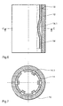
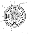
- FIGS. 10 and 11 show a connection socket as a further embodiment 1 in partial longitudinal section or as a cross-sectional representation along the line D ... D according to FIG. 10.
- the proximal end of the electrode line 4 is in the connection socket 1 introduced.
- the one positioned in the outer sleeve 10, made of spring sheet metal Manufactured inner sleeve 14 ' has a plurality of annular beads pointing radially outwards 16, which ensure a tight fit of the inner sleeve 14 '.
- the four in the Section plane according to Figure 11 evenly distributed on the sleeve circumference contact springs 14.1 'are strip-shaped and one-sided on the sleeve wall attached.
Landscapes
- Health & Medical Sciences (AREA)
- Engineering & Computer Science (AREA)
- Biomedical Technology (AREA)
- Nuclear Medicine, Radiotherapy & Molecular Imaging (AREA)
- Radiology & Medical Imaging (AREA)
- Life Sciences & Earth Sciences (AREA)
- Animal Behavior & Ethology (AREA)
- General Health & Medical Sciences (AREA)
- Public Health (AREA)
- Veterinary Medicine (AREA)
- Cardiology (AREA)
- Heart & Thoracic Surgery (AREA)
- Electrotherapy Devices (AREA)
Description
- Figur 1
- eine schematische Darstellung des Kopfteils eines Herzschrittmachers mit angeschlossener Elektrodenleitung,
- Figur 2
- eine perspektivische Darstellung einer bevorzugten Ausführungsform der Erfindung,
- Figur 3
- die Darstellung eines Schnittes längs der Linie A...A gemäß Figur 1,
- Figur 4
- die Darstellung eines Schnittes längs der Linie B...B gemäß Figur 3,
- Figur 5
- die Schnittdarstellung einer gegenüber Figur 4 modifizierten Weiterbildung der Erfindung,
- Figur 6
- einen Teil-Längsschnitt durch ein Vergleichsbeispiel zum Vergleich mit der Erfindung,
- Figur 7
- die Darstellung eines Schnittes längs der Linie C...C gemäß Figur 6,
- Figuren 8 und 9
- die in den Figuren 6 und 7 gezeigte Hülse in zwei verschiedenen Herstellungsstufen,
- Figur 10
- einen Teil-Längsschnitt durch ein weiteres Vergleichsbeispiel und
- Figur 11
- die Darstellung eines Schnittes längs der Linie D...D gemäß Figur 10.
Claims (11)
- Implantierbares Elektrostimulationsgerät (2) mit einem Kopfteil (3) zum elektrischen Anschluß einer Elektrodenleitung (4), das eine fest installierte Anschlußbuchse (1, 9) aufweist, an deren Innenwandung radial nach innen weisende Kontakt- und Haltemittel zum Eingriff mit einem Elektrodenleitungskontakt (5, 6) vorgesehen sind, wobei die Kontakt- und Haltemittel durch eine Mehrzahl von jeweils einen fest vorbestimmten Winkelabstand in Umfangsrichtung der Buchse und/oder axialen Abstand aufweisenden Nocken- oder Vorsprungsbereichen (10.1, 10.1') gebildet sind,
wobei die Nocken- oder Vorsprungsbereiche (10.1, 10.1') fest mit der Innenwandung verbunden oder aus dieser ausgeformt, sowie starr ausgebildet sind und dass die Nocken- oder Vorsprungsbereiche (10.1; 10.1') zum form- und vorzugsweise zusätzlich kraftschlüssigen Eingriff mit entsprechend angeordneten und geformten Bereichen (6.1) an einem Stift- oder Ringkontakt (5, 6) einer Elektrodenleitung (4) ausgebildet sind, und dass der formschlüssige und ggf. zusätzlich kraftschlüssige Eingriff durch eine Drehung des Stift- oder Ringkontakts (5, 6) um seine Längsachse herbeiführbar ist, wobei die Nocken- oder Vorsprungsbereiche der Anschlussbuchse ausgebildet sind, um von entsprechend angeordneten und geformten Bereichen (6.1) an einem Stift- oder Ringkontakt (5, 6) einer Elektrodenleitung (4) hintergriffen zu werden dadurch gekennzeichnet, dass die Nocken- oder Vorsprungsbereiche der Anschlußbuchse sich im wesentlichen radial erstreckende vordere und hintere Seitenflächen aufweisen, welche gegeneinander geneigt sind. - Elektrostimulationsgerät nach Anspruch 1, dadurch gekennzeichnet, dass die Nocken- oder Vorsprungsbereiche (10.1, 10.1') Eingriffsflächen aufweisen und die Nocken- oder Vorsprungsbereiche (10.1, 10.1') so angeordnet und ihre Eingriffsflächen so gestaltet sind, dass sie beim Eingriff mit den entsprechend angeordneten und geformten Bereichen (6.1, 6.1') des Stift- oder Ringkontakts (5, 6) unter Erzeugung einer Flächenpressung in Wirkkontakt geraten.
- Elektrostimulationsgerät nach einem der vorangehenden Ansprüche, dadurch gekennzeichnet, dass die Nocken- und Vorsprungsbereiche (10.1, 10.1') ein im wesentlichen keilförmiges Querschnittsprofil besitzen.
- Elektrostimulationsgerät einem der vorangehenden Ansprüche, dadurch gekennzeichnet, daß mindestens zwei Nocken- oder Vorsprungsbereiche (10.1; 10.1') bei übereinstimmender Lage in Umfangsrichtung in axialer Richtung gereiht sind.
- Elektrostimulationsgerät nach einem der vorhergehenden Ansprüche, dadurch gekennzeichnet, daß mindestens drei Nocken- oder Vorsprungsbereiche (10.1, 10.1') jeweils in einer sich quer zur Längsachse der Anschlußbuchse (1) erstreckenden Ebene, insbesondere in gleichem Winkelabstand zueinander, angeordnet sind.
- Elektrostimulationsgerät nach einem der vorangehenden Ansprüche, dadurch gekennzeichnet, daß die Anschlußbuchse (1) eine insgesamt aus einem leitfähigen Federmaterialblech geformte Innenhülse (10.2, 10.2') aufweist, welche die Nocken- oder Vorsprungsbereiche trägt.
- Elektrodenleitung (4) für ein implantierbares Elektrostimulationsgerät (2), die einen Stift- oder Ringkontakt (5, 6) zur Einführung in eine Anschlußbuchse (1, 9) des Elektrostimulationsgeräts aufweist, wobei an der Oberfläche des Stift- oder Ringkontaktes (5, 6) radial nach außen weisende Kontakt- und Haltemittel vorgesehen sind, die durch eine Mehrzahl von fest mit der Oberfläche verbundenen oder aus dieser ausgeformten, jeweils einen fest vorbestimmten Winkelabstand in Umfangsrichtung des Stift- oder Ringkontaktes (5, 6) und/oder axialen Abstand aufweisenden, Nocken- oder Vorsprungsbereichen (6.1, 6.1') gebildet sind, die Nocken- oder Vorsprungsbereiche (6.1, 6.1') zum form- und vorzugsweise zusätzlich kraftschlüssigen Eingriff mit entsprechend angeordneten und geformten Bereichen (10.1, 10.1') der Anschlussbuchse (1) des Elektrostimulationsgerätes (2) ausgebildet sind und die Nocken- oder Vorsprungsbereiche (6.1, 6.1') derart ausgebildet sind, dass der formschlüssige und ggf. zusätzlich kraftschlüssige Eingriff durch eine Drehung des Stift- oder Ringkontakts (5, 6) um seine Längsachse herbeiführbar ist, wobei die Nocken- oder Vorsprungsbereiche (6.1, 6.1') der Elektrodenleitung ausgebildet sind, um entsprechend angeordnete und geformte Nocken- oder Vorsprungsbereiche (10.1, 10.1') der Anschlussbuchse zu hintergreifen dadurch gekennzeichnet, dass die Nocken- oder Vorsprungsbereiche (6.1, 6.1') der Elektrodenleitung im wesentlichen radial erstreckende Seitenflächen aufweisen, welche gegenüber der tangentialen Richtung geneigt sind.
- Elektrodenleitung nach Anspruch 7, dadurch gekennzeichnet, dass die Nocken- oder Vorsprungsbereiche (6.1, 6.1') der Elektrodenleitung ein im wesentlichen keilförmiges Querschnittsprofil besitzen.
- Elektrodenleitung nach Anspruch 7 oder 8, dadurch gekennzeichnet, daß mindestens zwei Nocken- oder Vorsprungsbereiche (6.1, 6.1') der Elektrodenleitung bei übereinstimmender Lage in Umfangsrichtung in axialer Richtung gereiht sind.
- Elektrodenleitung nach einem der Ansprüche 7 bis 9, dadurch gekennzeichnet, daß die Nocken- oder Vorsprungsbereiche (6.1, 6.1') der Elektrodenleitung sich im wesentlichen radial erstreckende Seitenflächen aufweisen, welche gegeneinander geneigt sind.
- Elektrodenleitung nach einem der Ansprüche 7 bis 10, gekennzeichnet durch eine Ausbildung ihres proximales Endes derart, daß sie in der Anschlußbuchse (3) des Elektrostimulationsgerätes (2) mittels eines durch vorbestimmte Axialverschiebung und Drehung des Endes um einen vorbestimmten Winkel erzeugten Kraft- und/oder Formschlusses zwischen ihren Kontakt- und Haltemitteln (6.1, 6.1') mit solchen in der Buchse (3), insbesondere durch Flächenpressung an deren jeweils benachbarten Seitenflächen, verbindbar ist.
Applications Claiming Priority (2)
| Application Number | Priority Date | Filing Date | Title |
|---|---|---|---|
| DE19609367A DE19609367A1 (de) | 1996-03-04 | 1996-03-04 | Herzschrittmacher |
| DE19609367 | 1996-03-04 |
Publications (3)
| Publication Number | Publication Date |
|---|---|
| EP0793974A2 EP0793974A2 (de) | 1997-09-10 |
| EP0793974A3 EP0793974A3 (de) | 1999-04-21 |
| EP0793974B1 true EP0793974B1 (de) | 2004-09-15 |
Family
ID=7787851
Family Applications (1)
| Application Number | Title | Priority Date | Filing Date |
|---|---|---|---|
| EP97250058A Expired - Lifetime EP0793974B1 (de) | 1996-03-04 | 1997-03-04 | Implantierbares Elektrostimulationsgerät und Elektrodenleitung |
Country Status (3)
| Country | Link |
|---|---|
| US (1) | US5968082A (de) |
| EP (1) | EP0793974B1 (de) |
| DE (2) | DE19609367A1 (de) |
Families Citing this family (49)
| Publication number | Priority date | Publication date | Assignee | Title |
|---|---|---|---|---|
| US20050004642A1 (en) * | 1998-11-09 | 2005-01-06 | Medtronic, Inc. | Implantable medical lead including overlay |
| US6183305B1 (en) * | 1998-12-04 | 2001-02-06 | Pacesetter, Inc. | High strength connector design for passive fixation pacing lead |
| US6741892B1 (en) | 2000-03-10 | 2004-05-25 | Advanced Bionics Corporation | Movable contact locking mechanism for spinal cord stimulator lead connector |
| US6498952B2 (en) * | 2001-03-08 | 2002-12-24 | Pacesetter, Inc. | Hermetically sealed feedthrough connector using shape memory alloy for implantable medical device |
| US6895276B2 (en) * | 2002-02-28 | 2005-05-17 | Medtronic, Inc. | In-line lead header for an implantable medical device |
| US7130700B2 (en) * | 2002-11-19 | 2006-10-31 | Medtronic, Inc. | Multilumen body for an implantable medical device |
| US7539542B1 (en) | 2003-01-09 | 2009-05-26 | Boston Scientific Neuromodulation Corporation | Lead connector, lead adapter, and lead insertion apparatus |
| US7003351B2 (en) * | 2003-02-25 | 2006-02-21 | Cardiac Pacemakers, Inc. | Ring connector for implantable medical devices |
| US20050107859A1 (en) * | 2003-11-14 | 2005-05-19 | Terry Daglow | System and method of establishing an electrical connection between an implanted lead and an electrical contact |
| DE102004017659A1 (de) | 2004-04-05 | 2005-10-27 | Biotronik Vi Patent Ag | Federkontaktelement |
| DE102004053332B3 (de) * | 2004-11-04 | 2006-06-01 | Odu-Steckverbindungssysteme Gmbh & Co. Kg | Buchse eines elektrischen Steckverbinders |
| JP4801416B2 (ja) | 2004-11-04 | 2011-10-26 | オーデェウ ステッキフェルビンドゥングスシステエメ ゲゼルシャフト ミット ベシュレンクテル ハフツング ウント コンパニー コマンデイトゲゼルシャフト | 電気プラグ・コネクタのソケットおよびそのようなソケットを備えたプラグ・コネクタ |
| US7583999B2 (en) | 2006-07-31 | 2009-09-01 | Cranial Medical Systems, Inc. | Multi-channel connector for brain stimulation system |
| US20080262585A1 (en) * | 2007-04-20 | 2008-10-23 | Medtronic, Inc. | Implantable medical electrical lead and connector assembly |
| DE102007039554B4 (de) * | 2007-08-22 | 2010-07-29 | Osypka, Peter, Dr.- Ing. | Herzschrittmacher-Elektrode mit Schraubwendel und Zuleitungswendel |
| US9220889B2 (en) * | 2008-02-11 | 2015-12-29 | Intelect Medical, Inc. | Directional electrode devices with locating features |
| US8731670B2 (en) * | 2010-04-27 | 2014-05-20 | Oscor Inc. | Passive electrical connector |
| US8897876B2 (en) * | 2010-09-22 | 2014-11-25 | Boston Scientific Neuromodulation Corporation | Systems and methods for making and using connectors for electrical stimulation systems |
| WO2013062859A1 (en) * | 2011-10-28 | 2013-05-02 | Medtronic, Inc. | Modular lead end |
| US9017341B2 (en) * | 2011-10-31 | 2015-04-28 | Pacesetter, Inc. | Multi-piece dual-chamber leadless intra-cardiac medical device and method of implanting same |
| US9956394B2 (en) | 2015-09-10 | 2018-05-01 | Boston Scientific Neuromodulation Corporation | Connectors for electrical stimulation systems and methods of making and using |
| US10342983B2 (en) | 2016-01-14 | 2019-07-09 | Boston Scientific Neuromodulation Corporation | Systems and methods for making and using connector contact arrays for electrical stimulation systems |
| WO2017184484A1 (en) * | 2016-04-18 | 2017-10-26 | Cardiac Pacemakers, Inc. | Imd having anti-migration and device extraction features |
| US10201713B2 (en) | 2016-06-20 | 2019-02-12 | Boston Scientific Neuromodulation Corporation | Threaded connector assembly and methods of making and using the same |
| US10307602B2 (en) | 2016-07-08 | 2019-06-04 | Boston Scientific Neuromodulation Corporation | Threaded connector assembly and methods of making and using the same |
| EP3458154B1 (de) * | 2016-07-29 | 2025-11-12 | Boston Scientific Neuromodulation Corporation | Steckereinheit mit kontaktringen mit vorgespannten federkontakten mit jeweils einer kugel |
| US10543374B2 (en) | 2016-09-30 | 2020-01-28 | Boston Scientific Neuromodulation Corporation | Connector assemblies with bending limiters for electrical stimulation systems and methods of making and using same |
| US10905871B2 (en) | 2017-01-27 | 2021-02-02 | Boston Scientific Neuromodulation Corporation | Lead assemblies with arrangements to confirm alignment between terminals and contacts |
| US10814136B2 (en) | 2017-02-28 | 2020-10-27 | Boston Scientific Neuromodulation Corporation | Toolless connector for latching stimulation leads and methods of making and using |
| US10603499B2 (en) | 2017-04-07 | 2020-03-31 | Boston Scientific Neuromodulation Corporation | Tapered implantable lead and connector interface and methods of making and using |
| US10918873B2 (en) | 2017-07-25 | 2021-02-16 | Boston Scientific Neuromodulation Corporation | Systems and methods for making and using an enhanced connector of an electrical stimulation system |
| US11045656B2 (en) | 2017-09-15 | 2021-06-29 | Boston Scientific Neuromodulation Corporation | Biased lead connector for operating room cable assembly and methods of making and using |
| EP3681587B1 (de) | 2017-09-15 | 2023-08-23 | Boston Scientific Neuromodulation Corporation | Betätigbarer leitungsverbinder für eine kabelanordnung in einem op-saal |
| US11139603B2 (en) | 2017-10-03 | 2021-10-05 | Boston Scientific Neuromodulation Corporation | Connectors with spring contacts for electrical stimulation systems and methods of making and using same |
| US11103712B2 (en) | 2018-01-16 | 2021-08-31 | Boston Scientific Neuromodulation Corporation | Connector assemblies with novel spacers for electrical stimulation systems and methods of making and using same |
| US10992078B2 (en) | 2018-01-29 | 2021-04-27 | Bard Access Systems, Inc. | Connection system for establishing an electrical connection through a drape and methods thereof |
| WO2019217415A1 (en) | 2018-05-11 | 2019-11-14 | Boston Scientific Neuromodulation Corporation | Connector assembly for an electrical stimulation system |
| US10772696B2 (en) | 2018-05-18 | 2020-09-15 | Bard Access Systems, Inc. | Connection systems and methods thereof for establishing an electrical connection through a drape |
| CN109149202B (zh) * | 2018-07-20 | 2023-10-13 | 江苏农林职业技术学院 | 一种插座 |
| US11357992B2 (en) | 2019-05-03 | 2022-06-14 | Boston Scientific Neuromodulation Corporation | Connector assembly for an electrical stimulation system and methods of making and using |
| EP3997497B1 (de) | 2019-07-29 | 2025-08-27 | Bard Access Systems, Inc. | Verbindungssysteme und verfahren zur herstellung optischer und elektrischer verbindungen durch ein abdecktuch |
| WO2021026502A1 (en) | 2019-08-08 | 2021-02-11 | Bard Access Systems, Inc. | Optical-fiber connector modules including shape-sensing systems and methods thereof |
| US20230126905A1 (en) * | 2020-03-30 | 2023-04-27 | Incube Labs, Llc | Lead locking system and method for implantable stimulators |
| US20230144070A1 (en) * | 2020-04-21 | 2023-05-11 | Biotronik Se & Co. Kg | Connector of an implantable medical device |
| US11896814B2 (en) | 2020-05-04 | 2024-02-13 | Heartware, Inc. | Toolless quick connect sewing ring |
| US12121714B2 (en) | 2020-05-04 | 2024-10-22 | Heartware, Inc. | Sewing ring with quick connect to inflow |
| CN216285826U (zh) | 2020-10-28 | 2022-04-12 | 巴德阿克塞斯系统股份有限公司 | 连接系统及连接建立装置 |
| US12343547B2 (en) | 2021-08-19 | 2025-07-01 | Boston Scientific Neuromodulation Corporation | Connectors for an electrical stimulation system and methods of making and using |
| US12589252B2 (en) | 2021-08-19 | 2026-03-31 | Boston Scientific Neuromodulation Corporation | Connector assembly with capacitive contacts for an electrical stimulation system and methods of making and using |
Family Cites Families (15)
| Publication number | Priority date | Publication date | Assignee | Title |
|---|---|---|---|---|
| US3760332A (en) * | 1972-03-09 | 1973-09-18 | American Optical Corp | Pacer connector |
| US4112953A (en) * | 1977-03-11 | 1978-09-12 | Medcor, Inc. | Pacer stimulator with improved lead connector |
| DE2845175A1 (de) * | 1977-04-14 | 1980-04-24 | Biotronik Mess & Therapieg | Steckeraufnahme fuer den elektrodenanschluss eines implantierbaren herzschrittmachers |
| US4445511A (en) * | 1982-06-24 | 1984-05-01 | Telectronics Pty. Ltd. | Pacer electrode connector assembly |
| US4583543A (en) * | 1983-05-04 | 1986-04-22 | Cordis Corporation | Upsizing adapter |
| US4764132A (en) * | 1986-03-28 | 1988-08-16 | Siemens-Pacesetter, Inc. | Pacemaker connector block for proximal ring electrode |
| US5070605A (en) * | 1988-04-22 | 1991-12-10 | Medtronic, Inc. | Method for making an in-line pacemaker connector system |
| US4934367A (en) * | 1988-04-22 | 1990-06-19 | Medtronic, Inc. | In-line pacemaker connector system |
| US5088942A (en) * | 1990-09-07 | 1992-02-18 | Itt Corporation | Closed entry socket contact assembly |
| JP3235852B2 (ja) * | 1990-10-30 | 2001-12-04 | ジーイー・マーケット・メディカル・システムズ・インコーポレイテッド | 電極を支持体に対して電気的に接続するための装置 |
| US5261395A (en) * | 1992-03-02 | 1993-11-16 | Cardiac Pacemaker, Inc. | Tooless pulse generator to lead connection |
| US5252090A (en) * | 1992-09-30 | 1993-10-12 | Telectronics Pacing Systems, Inc. | Self-locking implantable stimulating lead connector |
| US5413595A (en) * | 1993-10-15 | 1995-05-09 | Pacesetter, Inc. | Lead retention and seal for implantable medical device |
| SE9600311D0 (sv) * | 1996-01-29 | 1996-01-29 | Pacesetter Ab | Fixeringsanordning |
| US5730628A (en) * | 1996-09-25 | 1998-03-24 | Pacesetter, Inc. | Multi-contact connector for an implantable medical device |
-
1996
- 1996-03-04 DE DE19609367A patent/DE19609367A1/de not_active Ceased
-
1997
- 1997-03-03 US US08/808,994 patent/US5968082A/en not_active Expired - Fee Related
- 1997-03-04 DE DE59711903T patent/DE59711903D1/de not_active Expired - Fee Related
- 1997-03-04 EP EP97250058A patent/EP0793974B1/de not_active Expired - Lifetime
Also Published As
| Publication number | Publication date |
|---|---|
| EP0793974A3 (de) | 1999-04-21 |
| US5968082A (en) | 1999-10-19 |
| DE59711903D1 (de) | 2004-10-21 |
| EP0793974A2 (de) | 1997-09-10 |
| DE19609367A1 (de) | 1997-09-11 |
Similar Documents
| Publication | Publication Date | Title |
|---|---|---|
| EP0793974A2 (de) | Implantierbares Elektrostimulationsgerät und Elektrodenleitung | |
| DE3702012C2 (de) | ||
| DE8508465U1 (de) | Verbinder mit einem drehbaren Einsatz zum Festhalten von Anschlüssen | |
| DE10054698A1 (de) | Elektrischer Steckverbinder, Kupplung und darin verwendbares Bauteil | |
| DE3887255T2 (de) | Selbstabisolierender Verbinder für einen elektrischen Leiter. | |
| DE2111777B2 (de) | Kontaktglied fuer einen elektrischen steckverbinder | |
| DE69917983T2 (de) | Kontaktstift | |
| DE102020103896B4 (de) | Anbaugehäuse für Steckverbindungen und Steckverbindersystem | |
| DE2359425A1 (de) | Kabelklemme und zugehoerige verbindungseinheit | |
| DE102015014492B4 (de) | Modulares Stecksystem, weiblicher Steckverbinder, männlicher Steckverbinder und Verfahren zum Zusammenstellen eines modularen Stecksystems | |
| DE2239476A1 (de) | Elektrischer verbinder und verfahren zur herstellung einer verbindung | |
| DE102004002921A1 (de) | Bandförmiges Kontaktelement, Verfahren zu seiner Herstellung, sowie Anwendung eines solchen Kontaktelements | |
| DE2323612A1 (de) | Elektrisches verbindungsglied | |
| DE3302924C3 (de) | Elektrische Steckverbindung | |
| DE10351099B3 (de) | Elektrischer Steckverbinder | |
| DE3408432A1 (de) | Fuer eine elektrische steckkontaktvorrichtung vorgesehenes kontaktstueck | |
| DE102005041922B4 (de) | Elektrische Steckverbindung mit federnden Brücken | |
| DE3637626C2 (de) | Verfahren zum Festlegen eines Metallstifts innerhalb eines keramischen Isolierkörpers | |
| DE69314854T2 (de) | Elektrischer Steckverbinder mit Anschlusselementverrieglung | |
| DE102017007358B4 (de) | Schraubsystem, Schraubverbinder und Verfahren zur Herstellung eines Schraubverbinders | |
| EP0922314B1 (de) | Muttersteckerteil für elektrische steckverbinder | |
| DE202011110604U1 (de) | Federdruckstück zur Herstellung eines elektrischen Federkontaktelements und elektrischer Steckverbinder | |
| DE19609625C2 (de) | Elektrischer Steckverbinder | |
| CH653178A5 (de) | Kontaktanordnung mit einem wickelpfosten. | |
| WO2025172107A1 (de) | Rundsteckverbinder mit schirmanbindung |
Legal Events
| Date | Code | Title | Description |
|---|---|---|---|
| PUAI | Public reference made under article 153(3) epc to a published international application that has entered the european phase |
Free format text: ORIGINAL CODE: 0009012 |
|
| AK | Designated contracting states |
Kind code of ref document: A2 Designated state(s): DE FR GB IT NL SE |
|
| PUAL | Search report despatched |
Free format text: ORIGINAL CODE: 0009013 |
|
| AK | Designated contracting states |
Kind code of ref document: A3 Designated state(s): DE FR GB IT NL SE |
|
| 17P | Request for examination filed |
Effective date: 19991014 |
|
| 17Q | First examination report despatched |
Effective date: 20010824 |
|
| GRAP | Despatch of communication of intention to grant a patent |
Free format text: ORIGINAL CODE: EPIDOSNIGR1 |
|
| GRAS | Grant fee paid |
Free format text: ORIGINAL CODE: EPIDOSNIGR3 |
|
| GRAA | (expected) grant |
Free format text: ORIGINAL CODE: 0009210 |
|
| AK | Designated contracting states |
Kind code of ref document: B1 Designated state(s): DE FR GB IT NL SE |
|
| REG | Reference to a national code |
Ref country code: GB Ref legal event code: FG4D Free format text: NOT ENGLISH |
|
| REG | Reference to a national code |
Ref country code: SE Ref legal event code: TRGR |
|
| GBT | Gb: translation of ep patent filed (gb section 77(6)(a)/1977) |
Effective date: 20040915 |
|
| REF | Corresponds to: |
Ref document number: 59711903 Country of ref document: DE Date of ref document: 20041021 Kind code of ref document: P |
|
| PLBE | No opposition filed within time limit |
Free format text: ORIGINAL CODE: 0009261 |
|
| STAA | Information on the status of an ep patent application or granted ep patent |
Free format text: STATUS: NO OPPOSITION FILED WITHIN TIME LIMIT |
|
| ET | Fr: translation filed | ||
| 26N | No opposition filed |
Effective date: 20050616 |
|
| PGFP | Annual fee paid to national office [announced via postgrant information from national office to epo] |
Ref country code: DE Payment date: 20060222 Year of fee payment: 10 |
|
| PGFP | Annual fee paid to national office [announced via postgrant information from national office to epo] |
Ref country code: NL Payment date: 20060320 Year of fee payment: 10 |
|
| PGFP | Annual fee paid to national office [announced via postgrant information from national office to epo] |
Ref country code: FR Payment date: 20060322 Year of fee payment: 10 |
|
| PGFP | Annual fee paid to national office [announced via postgrant information from national office to epo] |
Ref country code: IT Payment date: 20060331 Year of fee payment: 10 |
|
| PG25 | Lapsed in a contracting state [announced via postgrant information from national office to epo] |
Ref country code: SE Free format text: LAPSE BECAUSE OF NON-PAYMENT OF DUE FEES Effective date: 20070305 |
|
| EUG | Se: european patent has lapsed | ||
| GBPC | Gb: european patent ceased through non-payment of renewal fee |
Effective date: 20070304 |
|
| NLV4 | Nl: lapsed or anulled due to non-payment of the annual fee |
Effective date: 20071001 |
|
| REG | Reference to a national code |
Ref country code: FR Ref legal event code: ST Effective date: 20071130 |
|
| PG25 | Lapsed in a contracting state [announced via postgrant information from national office to epo] |
Ref country code: NL Free format text: LAPSE BECAUSE OF NON-PAYMENT OF DUE FEES Effective date: 20071001 Ref country code: DE Free format text: LAPSE BECAUSE OF NON-PAYMENT OF DUE FEES Effective date: 20071002 |
|
| PGFP | Annual fee paid to national office [announced via postgrant information from national office to epo] |
Ref country code: SE Payment date: 20060324 Year of fee payment: 10 |
|
| PG25 | Lapsed in a contracting state [announced via postgrant information from national office to epo] |
Ref country code: GB Free format text: LAPSE BECAUSE OF NON-PAYMENT OF DUE FEES Effective date: 20070304 |
|
| PG25 | Lapsed in a contracting state [announced via postgrant information from national office to epo] |
Ref country code: FR Free format text: LAPSE BECAUSE OF NON-PAYMENT OF DUE FEES Effective date: 20070402 |
|
| PGFP | Annual fee paid to national office [announced via postgrant information from national office to epo] |
Ref country code: GB Payment date: 20060323 Year of fee payment: 10 |
|
| PG25 | Lapsed in a contracting state [announced via postgrant information from national office to epo] |
Ref country code: IT Free format text: LAPSE BECAUSE OF NON-PAYMENT OF DUE FEES Effective date: 20070304 |