EP0793571B1 - Element de fixation a montage rapide - Google Patents
Element de fixation a montage rapide Download PDFInfo
- Publication number
- EP0793571B1 EP0793571B1 EP95936334A EP95936334A EP0793571B1 EP 0793571 B1 EP0793571 B1 EP 0793571B1 EP 95936334 A EP95936334 A EP 95936334A EP 95936334 A EP95936334 A EP 95936334A EP 0793571 B1 EP0793571 B1 EP 0793571B1
- Authority
- EP
- European Patent Office
- Prior art keywords
- attachment surface
- fastening assembly
- friction
- inner portion
- main
- Prior art date
- Legal status (The legal status is an assumption and is not a legal conclusion. Google has not performed a legal analysis and makes no representation as to the accuracy of the status listed.)
- Expired - Lifetime
Links
- 239000004831 Hot glue Substances 0.000 claims abstract description 76
- 239000000758 substrate Substances 0.000 claims abstract description 55
- 239000004820 Pressure-sensitive adhesive Substances 0.000 claims abstract description 39
- 238000003825 pressing Methods 0.000 claims abstract description 5
- 239000000463 material Substances 0.000 claims description 16
- 238000010438 heat treatment Methods 0.000 claims description 13
- 230000002093 peripheral effect Effects 0.000 claims description 12
- 239000002184 metal Substances 0.000 claims description 11
- 229910052751 metal Inorganic materials 0.000 claims description 11
- 238000001816 cooling Methods 0.000 abstract 1
- 239000010410 layer Substances 0.000 description 67
- 239000000853 adhesive Substances 0.000 description 22
- 230000001070 adhesive effect Effects 0.000 description 22
- 239000000155 melt Substances 0.000 description 8
- 230000000712 assembly Effects 0.000 description 6
- 238000000429 assembly Methods 0.000 description 6
- 239000007767 bonding agent Substances 0.000 description 6
- 238000009987 spinning Methods 0.000 description 6
- 238000003466 welding Methods 0.000 description 6
- 239000004567 concrete Substances 0.000 description 4
- 238000002844 melting Methods 0.000 description 4
- 230000008018 melting Effects 0.000 description 4
- 239000006260 foam Substances 0.000 description 3
- 239000012528 membrane Substances 0.000 description 3
- 229920001169 thermoplastic Polymers 0.000 description 3
- 239000004416 thermosoftening plastic Substances 0.000 description 3
- 229910052782 aluminium Inorganic materials 0.000 description 2
- XAGFODPZIPBFFR-UHFFFAOYSA-N aluminium Chemical compound [Al] XAGFODPZIPBFFR-UHFFFAOYSA-N 0.000 description 2
- 239000012943 hotmelt Substances 0.000 description 2
- 239000004005 microsphere Substances 0.000 description 2
- 239000000203 mixture Substances 0.000 description 2
- 238000013021 overheating Methods 0.000 description 2
- 239000008188 pellet Substances 0.000 description 2
- 229920001187 thermosetting polymer Polymers 0.000 description 2
- 239000002023 wood Substances 0.000 description 2
- RYGMFSIKBFXOCR-UHFFFAOYSA-N Copper Chemical compound [Cu] RYGMFSIKBFXOCR-UHFFFAOYSA-N 0.000 description 1
- 239000013032 Hydrocarbon resin Substances 0.000 description 1
- 239000004952 Polyamide Substances 0.000 description 1
- 239000004697 Polyetherimide Substances 0.000 description 1
- 239000004698 Polyethylene Substances 0.000 description 1
- 239000004734 Polyphenylene sulfide Substances 0.000 description 1
- 229910000831 Steel Inorganic materials 0.000 description 1
- 230000004913 activation Effects 0.000 description 1
- 239000012790 adhesive layer Substances 0.000 description 1
- 230000004888 barrier function Effects 0.000 description 1
- 239000011324 bead Substances 0.000 description 1
- 230000008901 benefit Effects 0.000 description 1
- 239000004566 building material Substances 0.000 description 1
- 230000015556 catabolic process Effects 0.000 description 1
- 238000002485 combustion reaction Methods 0.000 description 1
- 229910052802 copper Inorganic materials 0.000 description 1
- 239000010949 copper Substances 0.000 description 1
- 238000006731 degradation reaction Methods 0.000 description 1
- 238000009826 distribution Methods 0.000 description 1
- 230000000694 effects Effects 0.000 description 1
- 230000006870 function Effects 0.000 description 1
- 230000017525 heat dissipation Effects 0.000 description 1
- 229920006270 hydrocarbon resin Polymers 0.000 description 1
- 238000001746 injection moulding Methods 0.000 description 1
- 239000000314 lubricant Substances 0.000 description 1
- 238000004519 manufacturing process Methods 0.000 description 1
- 238000000034 method Methods 0.000 description 1
- 238000005065 mining Methods 0.000 description 1
- 238000000465 moulding Methods 0.000 description 1
- 239000003973 paint Substances 0.000 description 1
- 239000004033 plastic Substances 0.000 description 1
- 229920003023 plastic Polymers 0.000 description 1
- 229920006162 poly(etherimide sulfone) Polymers 0.000 description 1
- 229920002492 poly(sulfone) Polymers 0.000 description 1
- 229920002647 polyamide Polymers 0.000 description 1
- 239000004417 polycarbonate Substances 0.000 description 1
- 229920000515 polycarbonate Polymers 0.000 description 1
- -1 polyethylene Polymers 0.000 description 1
- 229920000573 polyethylene Polymers 0.000 description 1
- 229920000069 polyphenylene sulfide Polymers 0.000 description 1
- 229920002689 polyvinyl acetate Polymers 0.000 description 1
- 239000011118 polyvinyl acetate Substances 0.000 description 1
- 230000008569 process Effects 0.000 description 1
- 239000007787 solid Substances 0.000 description 1
- 239000010959 steel Substances 0.000 description 1
- 239000003039 volatile agent Substances 0.000 description 1
Images


Classifications
-
- F—MECHANICAL ENGINEERING; LIGHTING; HEATING; WEAPONS; BLASTING
- F16—ENGINEERING ELEMENTS AND UNITS; GENERAL MEASURES FOR PRODUCING AND MAINTAINING EFFECTIVE FUNCTIONING OF MACHINES OR INSTALLATIONS; THERMAL INSULATION IN GENERAL
- F16B—DEVICES FOR FASTENING OR SECURING CONSTRUCTIONAL ELEMENTS OR MACHINE PARTS TOGETHER, e.g. NAILS, BOLTS, CIRCLIPS, CLAMPS, CLIPS OR WEDGES; JOINTS OR JOINTING
- F16B11/00—Connecting constructional elements or machine parts by sticking or pressing them together, e.g. cold pressure welding
- F16B11/006—Connecting constructional elements or machine parts by sticking or pressing them together, e.g. cold pressure welding by gluing
-
- B—PERFORMING OPERATIONS; TRANSPORTING
- B29—WORKING OF PLASTICS; WORKING OF SUBSTANCES IN A PLASTIC STATE IN GENERAL
- B29C—SHAPING OR JOINING OF PLASTICS; SHAPING OF MATERIAL IN A PLASTIC STATE, NOT OTHERWISE PROVIDED FOR; AFTER-TREATMENT OF THE SHAPED PRODUCTS, e.g. REPAIRING
- B29C65/00—Joining or sealing of preformed parts, e.g. welding of plastics materials; Apparatus therefor
- B29C65/02—Joining or sealing of preformed parts, e.g. welding of plastics materials; Apparatus therefor by heating, with or without pressure
- B29C65/06—Joining or sealing of preformed parts, e.g. welding of plastics materials; Apparatus therefor by heating, with or without pressure using friction, e.g. spin welding
- B29C65/0672—Spin welding
-
- B—PERFORMING OPERATIONS; TRANSPORTING
- B29—WORKING OF PLASTICS; WORKING OF SUBSTANCES IN A PLASTIC STATE IN GENERAL
- B29C—SHAPING OR JOINING OF PLASTICS; SHAPING OF MATERIAL IN A PLASTIC STATE, NOT OTHERWISE PROVIDED FOR; AFTER-TREATMENT OF THE SHAPED PRODUCTS, e.g. REPAIRING
- B29C65/00—Joining or sealing of preformed parts, e.g. welding of plastics materials; Apparatus therefor
- B29C65/02—Joining or sealing of preformed parts, e.g. welding of plastics materials; Apparatus therefor by heating, with or without pressure
- B29C65/06—Joining or sealing of preformed parts, e.g. welding of plastics materials; Apparatus therefor by heating, with or without pressure using friction, e.g. spin welding
- B29C65/069—Joining or sealing of preformed parts, e.g. welding of plastics materials; Apparatus therefor by heating, with or without pressure using friction, e.g. spin welding the welding tool cooperating with specially formed features of at least one of the parts to be joined, e.g. cooperating with holes or ribs of at least one of the parts to be joined
-
- B—PERFORMING OPERATIONS; TRANSPORTING
- B29—WORKING OF PLASTICS; WORKING OF SUBSTANCES IN A PLASTIC STATE IN GENERAL
- B29C—SHAPING OR JOINING OF PLASTICS; SHAPING OF MATERIAL IN A PLASTIC STATE, NOT OTHERWISE PROVIDED FOR; AFTER-TREATMENT OF THE SHAPED PRODUCTS, e.g. REPAIRING
- B29C65/00—Joining or sealing of preformed parts, e.g. welding of plastics materials; Apparatus therefor
- B29C65/48—Joining or sealing of preformed parts, e.g. welding of plastics materials; Apparatus therefor using adhesives, i.e. using supplementary joining material; solvent bonding
- B29C65/4805—Joining or sealing of preformed parts, e.g. welding of plastics materials; Apparatus therefor using adhesives, i.e. using supplementary joining material; solvent bonding characterised by the type of adhesives
- B29C65/481—Non-reactive adhesives, e.g. physically hardening adhesives
- B29C65/4815—Hot melt adhesives, e.g. thermoplastic adhesives
-
- B—PERFORMING OPERATIONS; TRANSPORTING
- B29—WORKING OF PLASTICS; WORKING OF SUBSTANCES IN A PLASTIC STATE IN GENERAL
- B29C—SHAPING OR JOINING OF PLASTICS; SHAPING OF MATERIAL IN A PLASTIC STATE, NOT OTHERWISE PROVIDED FOR; AFTER-TREATMENT OF THE SHAPED PRODUCTS, e.g. REPAIRING
- B29C65/00—Joining or sealing of preformed parts, e.g. welding of plastics materials; Apparatus therefor
- B29C65/48—Joining or sealing of preformed parts, e.g. welding of plastics materials; Apparatus therefor using adhesives, i.e. using supplementary joining material; solvent bonding
- B29C65/4805—Joining or sealing of preformed parts, e.g. welding of plastics materials; Apparatus therefor using adhesives, i.e. using supplementary joining material; solvent bonding characterised by the type of adhesives
- B29C65/481—Non-reactive adhesives, e.g. physically hardening adhesives
- B29C65/4825—Pressure sensitive adhesives
-
- B—PERFORMING OPERATIONS; TRANSPORTING
- B29—WORKING OF PLASTICS; WORKING OF SUBSTANCES IN A PLASTIC STATE IN GENERAL
- B29C—SHAPING OR JOINING OF PLASTICS; SHAPING OF MATERIAL IN A PLASTIC STATE, NOT OTHERWISE PROVIDED FOR; AFTER-TREATMENT OF THE SHAPED PRODUCTS, e.g. REPAIRING
- B29C65/00—Joining or sealing of preformed parts, e.g. welding of plastics materials; Apparatus therefor
- B29C65/78—Means for handling the parts to be joined, e.g. for making containers or hollow articles, e.g. means for handling sheets, plates, web-like materials, tubular articles, hollow articles or elements to be joined therewith; Means for discharging the joined articles from the joining apparatus
- B29C65/7855—Provisory fixing
-
- B—PERFORMING OPERATIONS; TRANSPORTING
- B29—WORKING OF PLASTICS; WORKING OF SUBSTANCES IN A PLASTIC STATE IN GENERAL
- B29C—SHAPING OR JOINING OF PLASTICS; SHAPING OF MATERIAL IN A PLASTIC STATE, NOT OTHERWISE PROVIDED FOR; AFTER-TREATMENT OF THE SHAPED PRODUCTS, e.g. REPAIRING
- B29C66/00—General aspects of processes or apparatus for joining preformed parts
- B29C66/01—General aspects dealing with the joint area or with the area to be joined
- B29C66/05—Particular design of joint configurations
- B29C66/10—Particular design of joint configurations particular design of the joint cross-sections
- B29C66/11—Joint cross-sections comprising a single joint-segment, i.e. one of the parts to be joined comprising a single joint-segment in the joint cross-section
- B29C66/112—Single lapped joints
- B29C66/1122—Single lap to lap joints, i.e. overlap joints
-
- B—PERFORMING OPERATIONS; TRANSPORTING
- B29—WORKING OF PLASTICS; WORKING OF SUBSTANCES IN A PLASTIC STATE IN GENERAL
- B29C—SHAPING OR JOINING OF PLASTICS; SHAPING OF MATERIAL IN A PLASTIC STATE, NOT OTHERWISE PROVIDED FOR; AFTER-TREATMENT OF THE SHAPED PRODUCTS, e.g. REPAIRING
- B29C66/00—General aspects of processes or apparatus for joining preformed parts
- B29C66/40—General aspects of joining substantially flat articles, e.g. plates, sheets or web-like materials; Making flat seams in tubular or hollow articles; Joining single elements to substantially flat surfaces
- B29C66/47—Joining single elements to sheets, plates or other substantially flat surfaces
- B29C66/474—Joining single elements to sheets, plates or other substantially flat surfaces said single elements being substantially non-flat
-
- B—PERFORMING OPERATIONS; TRANSPORTING
- B29—WORKING OF PLASTICS; WORKING OF SUBSTANCES IN A PLASTIC STATE IN GENERAL
- B29C—SHAPING OR JOINING OF PLASTICS; SHAPING OF MATERIAL IN A PLASTIC STATE, NOT OTHERWISE PROVIDED FOR; AFTER-TREATMENT OF THE SHAPED PRODUCTS, e.g. REPAIRING
- B29C66/00—General aspects of processes or apparatus for joining preformed parts
- B29C66/70—General aspects of processes or apparatus for joining preformed parts characterised by the composition, physical properties or the structure of the material of the parts to be joined; Joining with non-plastics material
- B29C66/71—General aspects of processes or apparatus for joining preformed parts characterised by the composition, physical properties or the structure of the material of the parts to be joined; Joining with non-plastics material characterised by the composition of the plastics material of the parts to be joined
-
- B—PERFORMING OPERATIONS; TRANSPORTING
- B29—WORKING OF PLASTICS; WORKING OF SUBSTANCES IN A PLASTIC STATE IN GENERAL
- B29C—SHAPING OR JOINING OF PLASTICS; SHAPING OF MATERIAL IN A PLASTIC STATE, NOT OTHERWISE PROVIDED FOR; AFTER-TREATMENT OF THE SHAPED PRODUCTS, e.g. REPAIRING
- B29C66/00—General aspects of processes or apparatus for joining preformed parts
- B29C66/80—General aspects of machine operations or constructions and parts thereof
- B29C66/83—General aspects of machine operations or constructions and parts thereof characterised by the movement of the joining or pressing tools
- B29C66/832—Reciprocating joining or pressing tools
- B29C66/8322—Joining or pressing tools reciprocating along one axis
-
- B—PERFORMING OPERATIONS; TRANSPORTING
- B29—WORKING OF PLASTICS; WORKING OF SUBSTANCES IN A PLASTIC STATE IN GENERAL
- B29L—INDEXING SCHEME ASSOCIATED WITH SUBCLASS B29C, RELATING TO PARTICULAR ARTICLES
- B29L2031/00—Other particular articles
- B29L2031/727—Fastening elements
- B29L2031/7282—Snap fasteners, clips, press-buttons
Definitions
- the invention concerns a fastening assembly that can be mounted in seconds on a wall, a ceiling, a cabinet, a support, a workpiece, or other substrate and then put to immediate use to mount articles such as a fixture, a picture, or a conduit. More specifically, the invention concerns a quick-mounting fastening assembly that bears a hot-melt adhesive by which it can be permanently bonded to a surface, e.g., by "spin welding” or “friction welding” (that is, spinning an adhesive-bearing device against a surface until the frictional heat melts the adhesive, then stopping the rotation to allow the adhesive to congeal to form a bond between the device and the surface).
- hot-melt adhesive is here used to encompass “heat-activated adhesive” and "thermoplastic adhesive”.
- a stud is permanently bonded to a workpiece by spin welding.
- a stud 1 has a base 3 with a recess 6 into which a hot-melt adhesive 4 has been deposited.
- a rotary tool engages the shank 2 of the stud to rotate the stud at a fairly high speed so that friction between opposed faces of the hot-melt adhesive and the workpiece generates heat to melt the adhesive.
- US-A-4,566,924 it is said that "when the stud adheres to the workpiece, the tool will sense the completion of the adhesion by breaking the projected portion 3' [see Figure 2(A)] and will come to a stop" (col.
- the shank of the stud of Figure 1 can be used for retaining an electric cable or some other wire material; that of Figure 2, for swingably retaining the ball of a ball joint; and that of Figure 3, for attaching a molding to an automobile body.
- US-A-4,477,307 says known spin welding involved the problem of melting the adhesive sufficiently to create the desired bond without overheating the adhesive to the point of combustion.
- a stud-like fastening element 42 of Figure 4 of US-A-4,477,307 has a tapered base 46 so that the central portion melts first. After the melting reaches the periphery of the base, a peripheral protrusion 50, by which a special tool rotates the fastening element, is sheared off, thus stopping the rotation and preventing overheating.
- US-A-4,636,124 says: "Friction weld fastener systems, such as disclosed in US-A-4,477,307, do not provide adequate adhesion with some surfaces such as wood or painted metal.
- One known manner of increasing the adhesion characteristics for such surfaces is to add a heat activated adhesive pellet at the center of the friction weld fastener. Upon axial and rotational forces being applied to the base of the fastener, the heat-activated adhesive melts and spreads across the friction weld surface" (col. 1, lines 10-18).
- US-A-4,636,124 concerns means for providing even distribution of adhesive from the pellet.
- thermoplastic button 20 of Figures 1 and 2 of US-A-3,468,732 is spin welded to the abutting edges of two thermoplastic sheets, thus welding the sheets together.
- a tip 22a at the conical working face of the button acts like a center punch to prevent skidding or skating of the button on the surface of the sheets (col. 3, lines 22-27).
- the stud-like fastening element 42 of Figure 4 of US-A-4,477,307 has a similar protrusion 48, but I fail to find any mention of its utility in the Cearlock specification.
- a foot plate is bonded to a substrate by a bonding agent 20 which "may comprise a hot melt or thermoset adhesive material" (col. 10, lines 21-23).
- a bonding agent 20 which "may comprise a hot melt or thermoset adhesive material" (col. 10, lines 21-23).
- Figures 16-20 are of particular interest to the present invention because the mounting fixture 18 of Figures 16-20 is "secured at least temporarily to the substrate 12 by means of the pressure sensitive adhesive 100" (col. 10, lines 4-6) on the connector rim 98 of the mounting fixture 18, as best seen in Figure 20.
- the bonding agent 20, which "may comprise a hot melt or thermoset adhesive material" (col. 10, lines 21-22) is activated by heat conducted downwardly as indicated by arrows 112 of Figure 19.
- a circular wafer that conducts heat to fuse a hot-melt adhesive is employed in the Hang FastTM wall mounting system of Sears Roebuck and Co., Chicago, IL which is identical to the prior art shown in Figures 1-3 of US-A-4,923,159.
- a plastic mounting disk (B) has a thin membrane (B2), one surface of which is covered by a hot-melt adhesive layer (B3).
- a heating device which contacts the membrane (B2) presses the adhesive layer (B3) against a support, and heat conducted through the membrane fuses the adhesive to bond the disk to the support.
- the mounting disk is formed with a peripheral flange which acts as a seat for a hook, like that shown in Figure 6 of US-A-4,923,159.
- the novel quick-mounting fastening assembly includes a fastening structure having an initial attachment surface and a main attachment surface that is approximately co-planar with the initial attachment surface.
- a layer of pressure-sensitive adhesive on the initial attachment surface affords adhering the fastening assembly to a substrate by pressing it against that substrate.
- a layer of hot-melt adhesive is on the main attachment surface; and frictional heating means is provided for affording sufficient frictional heating to melt the layer of hot-melt adhesive with the layer of pressure sensitive adhesive adhered to the substrate so that when the layer of hot melt adhesive again solidifies, it will be adhered to the substrate.
- the fastening structure includes an inner portion having the main attachment surface; and an outer portion having the initial attachment surface, with the initial attachment surface encompassing the main attachment surface.
- the outer portion has a through circular opening; the inner portion is generally circular about an axis normal to the main attachment surface; the inner and outer portions include means mounting the inner portion for rotation within the outer portion, and the frictional heating means comprises driving engagement means on the inner portion for releasably connecting the inner portion to a source of rotational power to rotate the inner portion about its axis with the layer of hot-melt adhesive in contact with the substrate surface to melt the layer of hot-melt adhesive.
- That inner portion can have a coaxial socket shaped to receive the end of a drive member, which socket can be formed in a stud-like part projecting coaxially on the side of the inner portion opposite the main attachment surface.
- the outer and inner portions are fixed to or integral with each other, the inner portion has a generally planar friction surface opposite and generally parallel to the main attachment surface, the inner portion has a thin cross sectional area and is of a material (e.g., metal or heat resistant polymeric material) adapted to conduct heat energy between the friction surface and the main attachment surface, the fastening structure has a socket defined by surfaces including the friction surface, and the fastening assembly further includes a friction disk having a planar friction surface, means mounting the friction disk in the socket with the friction surfaces adjacent for rotation about an axis normal to the friction surfaces, and driving engagement means on the friction disk for releasably connecting the friction disk to a source of rotational power to rotate the friction disk about the axis with the friction surfaces in contact to heat the inner portion and thereby melt the layer of hot-melt adhesive by heat transfer through the inner portion.
- That friction disk can have a coaxial socket shaped to receive the end of a drive member, which socket can be formed in a stud-like part projecting co
- the outer and inner portions are attached to or integral with each other, the inner portion has a generally planar friction surface opposite and generally parallel to the main attachment surface, the inner portion is of a material (e.g., metal or heat resistant polymeric material) adapted to conduct heat energy between the friction surface and the main attachment surface, and the fastening structure has a socket defined by surfaces including the friction surface adapted to receive and have a friction disk (which is not a part of the fastening assembly) rotated therein with a planar friction surface on the friction disk in contact with the friction surface on the inner surface to heat and thereby melt the layer of hot-melt adhesive by heat transfer through the inner portion.
- a material e.g., metal or heat resistant polymeric material
- the initial attachment surface can extend entirely around the main attachment surface so that it and the layer of pressure sensitive adhesive form an encircling dam to retain the layer of hot-melt adhesive when it is melted; and the outer portion can include a radially outwardly projecting flange spaced from the initial attachment surface so that means for engaging the fastening assembly can be received around the periphery of the outer portion between the flange and a surface to which the attachment assembly is adhered.
- the inner and outer portions of any of the embodiments can be of a polymeric material and can be formed by injection molding.
- the inner and outer portions can be a single piece of tough, heat-resistant polymeric material such as high-temperature polycarbonate, polyphenylene sulfide, polyether imide, or polysulfone, with the inner portion preferably being from 0.25 to 1.25 mm (0.010 to 0.050 inch) in thickness between its friction and main attachment surfaces. At thicknesses substantially below that range, the inner portion might have insufficient strength while thicknesses substantially above that range might excessively slow the melting of the hot-melt adhesive.
- An inner portion of metal e.g., steel, aluminum, or copper in either of the latter two embodiments affords rapid heating of the hot-melt adhesive, but adds to the expense of the fastening assembly.
- the pressure-sensitive adhesive used on the initial attachment surface of the fastening assembly preferably is repositionable to enable the fastening assembly to be positioned with precision before frictionally heating the hot-melt adhesive.
- Preferred repositionable pressure-sensitive adhesives are based on hollow tacky microspheres as disclosed in US-A-5,045,569 or solid tacky microspheres as disclosed in US-A-3,691,140.
- a preferred class is disclosed in US-A-Re. 24,906.
- a pressure-sensitive adhesive is visco-elastic, is permanently tacky at ordinary room temperatures, and adheres instantaneously to most surfaces under fingertip pressure.
- the layer of pressure-sensitive adhesive on the initial attachment surface has or can have several functions: 1) it resists any tendency of the frictional heating means to laterally move or "walk” the fastening assembly out of position, 2) it can (if it is continuous around the inner portion) act as a dam to contain melted hot-melt adhesive within the outer portion, 3) it holds the fastening structure in place while the hot-melt adhesive cools, and 4) when the pressure-sensitive adhesive is repositionable, it allows the fastening assembly to be positioned temporarily while the installer checks the accuracy of its position. When the pressure-sensitive adhesive is not repositionable, it can enhance the holding force of the fastening assembly.
- the layer of pressure-sensitive adhesive on the initial attachment surface preferably has a uniform thickness of at least 50 m m (0.002 inch), more preferably at least 100 m m (0.004 inch) to permit the fastening assembly to be adhered to a rough substrate such as a concrete block and, when so adhered, to be more effective to prevent walking and, when so used, as a dam for the melted hot-melt adhesive.
- the pressure-sensitive adhesive preferably includes a layer selected from 1) a pressure-sensitive adhesive foam, 2) a foam-like pressure-sensitive adhesive such as is disclosed in US-A-4,223,067, and 3) a polymeric foam web; however, a thick layer of pressure sensitive adhesive could also be used. Each of those foam and foam-like layers provides the additional benefit of being temporarily compressible to allow the hot-melt adhesive to be pushed, if necessary, into contact with a substrate to which the fastening assembly is being bonded.
- the hot-melt adhesive used on the main attachment surface of the fastening structure can be based on any polymeric material which is strong, tough and non-tacky at ordinary room temperatures, fuses at moderately elevated temperatures to form strong bonds to common building materials such as concrete, wood, metal, and paint, and does not produce any volatiles when fused.
- Typical hot-melt adhesives are based on polyethylene, polyamides, polyvinyl acetate, and hydrocarbon resins.
- Useful commercially available hot-melt adhesives include the Versamid and Macromelt adhesives from Henkel and those sold under the trade designation "Jet-melt adhesives Nos. 3762LM and 3738 by Minnesota Mining and Manufacturing Company, St Paul, Minnesota.
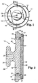
- FIGs 1 and 2 illustrate a first embodiment of a quick-mounting fastening assembly according to the present invention generally designated by the reference numeral 10.
- the fastening assembly 10 includes a fastening structure 11 including a generally circular outer portion 12 which has an annular generally planar initial attachment surface 13 and a central opening 15. Covering the initial attachment surface 13 is a layer 17 of pressure-sensitive adhesive that preferably is a foamed or foam-like layer and is protected by a removable release liner 18. Coaxially positioned within the central opening 15 and totally encompassed by the outer portion 12 is a disk-shaped part 19 of an inner portion 20 of the fastening structure 11.
- the inner portion 20 has a planar main attachment surface 21 that is approximately co-planar with the initial attachment surface 13 and faces in the same direction as the initial attachment surface 13.
- the main attachment surface 21 is covered by a layer 22 of hot-melt adhesive.
- the inner portion 20 also includes a stud-like part 24 projecting from the side of the disk-shaped part 19 opposite its main attachment surface 21, which stud-like part has a socket 25 with an hexagonal cross section that is coaxial with the stud-like part 24 and the disk-shaped part 19 of the inner portion 20.
- the outer portion 12 includes a circular radially inwardly projecting ridge 26, and the outer and inner portions 12 and 20 have sufficient resilient flexibility to permit the disk-shaped part 19 of the inner portion 20 to be pushed into the central opening 15 until the ridge 26 loosely fits into a circumferential recess 27 around the disk-shaped part 19.
- the loose fit (1) permits the layer 17 of pressure-sensitive adhesive (after removal of the release liner 18) to adhere to a flat substrate (indicated by a phantom line 28), (2) permits the exposed face of the layer 22 of hot-melt adhesive to be pushed into full contact with the substrate by a rotary tool (not shown) in driving engagement in the hexagonal socket 25, and enables the inner portion 20 to be rotated freely within the outer portion 12.
- the typical layer 22 of hot-melt adhesive melts within a few seconds. As soon as the adhesive melts, the tool is stopped, and the layer 22 of melted hot-melt adhesive quickly congeals or solidifies to bond the fastening assembly 10 to the substrate.
- a radially outwardly projecting flange 29 around and included in the stud-like part 24 can be releasably engaged by any of a variety of devices such as a flexible clip that can retain cables, wires, cords, and the like.
- the outer portion 12 comprises a flange 23 projecting radially outwardly of the outer periphery of the initial attachment surface 13.
- the flange 23 is spaced from the initial attachment surface 13 and the outer portion has a peripheral surface between the flange 23 and the outer periphery of the initial attachment surface 13 adapted to receive means (e.g., a picture wire) for engaging the fastening assembly to seat or attach various articles after the fastening assembly 10 has been mounted on a substrate.
- the fastening assembly 30 includes a fastening structure 31 including a circular outer portion 32 which has an annular generally planar initial attachment surface 33 covered by a layer 35 of pressure-sensitive adhesive that preferably is a foamed or foam-like layer and is protected by a removable release liner 36.
- the fastening structure 31 also includes an inner portion 34 that has a main attachment surface 37 covered by a layer 38 of hot-melt adhesive that is about co-planar with, but is slightly recessed with respect to the face of the layer 35 of pressure-sensitive adhesive, and a generally planar friction surface 39 opposite and generally parallel to its main attachment surface 37.
- the inner portion 34 has a thin cross sectional area adapted to conduct heat energy between the friction surface 39 and the main attachment surface 37.
- the fastening structure 31 has a socket 40 defined by its surfaces including the friction surface 39, and the fastening assembly 30 further includes a friction disk 41 having a planar friction surface 42, means mounting the friction disk 41 in the socket 40 with the friction surfaces 39 and 42 adjacent for rotation about an axis normal to the friction surfaces 39 and 42, and driving engagement means provided by a socket 43 shaped to receive the tip of a "Phillips" type screw driver (not shown) in the friction disk 41 for releasably connecting the friction disk 41 to a source of rotational power to rotate the friction disk 41 about its axis with the friction surfaces 39 and 42 in contact to heat the inner portion 34 and thereby melt the layer of hot-melt adhesive by heat transfer through the inner portion 34.
- the means mounting the friction disk 41 in the socket 40 is provided by a peripheral rim 44 of the friction disk 41 that is loosely received in a circular recess 45 in the outer portion 32.
- the outer portion 32 and the friction disk 41 together have sufficient resilience to permit the peripheral rib 44 of the friction disk 41 to be pushed into the circular recess 45 until it loosely fits in the recess 45.
- the release liner 36 is removed and the layer 35 of pressure-sensitive adhesive is pressed against a flat surface of the substrate.
- friction between the friction surfaces 42 and 39 of the rotating friction disk 41 and the inner portion 34 generates heat that is conducted through the inner portion 34 to melt the layer 38 of hot-melt adhesive and thereby bond the fastening assembly 30 to the substrate after rotation of the friction disk 41 is stopped so that the hot melt adhesive is again allowed to solidify.
- the outer portion 32 comprises a flange 46 projecting radially outwardly of the outer periphery of the initial attachment surface 33.
- the flange 46 is spaced from the initial attachment surface 33 and the outer portion 32 has a peripheral surface between the flange 46 and the outer periphery of the initial attachment surface 33 adapted to receive means (e.g., a picture wire) for engaging the fastening assembly to support various articles or implements after the fastening assembly 30 has been mounted on a substrate.
- FIG 4 illustrates a quick-mounting fastening assembly 50 which, like the fastening assembly 30 illustrated in Figure 3, can be easily removed after being bonded to a substrate.
- the fastening assembly 50 includes a fastening structure 51 including a circular polymeric outer portion 52 which has an annular generally planar initial attachment surface 53 covered by a layer 55 of pressure-sensitive adhesive that preferably is a foamed or foam-like layer and is protected by a removable release liner 56, and a metal inner portion 54 fixed around its periphery in the outer portion 52 that has a main attachment surface 57 covered by a layer 58 of hot-melt adhesive having a face that is about co-planar with, but is slightly recessed with respect to the face of the layer 55 of pressure-sensitive adhesive, and a generally planar friction surface 59 opposite and generally parallel to its main attachment surface 57.
- the metal inner portion 54 has a thin cross sectional area adapted to conduct heat energy between the friction surface 59 and the main attachment surface 57.
- the fastening structure 51 has a socket 60 defined by its surfaces including the friction surface 59, and the fastening assembly 50 further includes a friction disk 61 having a planar friction surface 62, means mounting the friction disk 61 in the socket 60 with the friction surfaces 59 and 62 adjacent for rotation about an axis normal to the friction surfaces 59 and 62, and driving engagement means provided by a knob 66 integral and co-axial with the disk 61 that is in the shape of a hex nut which provides means for releasably connecting the friction disk 61 to a source of rotational power to rotate the friction disk 61 about its axis with the friction surfaces 59 and 62 in contact to heat the metal inner portion 54 and thereby melt the layer 58 of hot-melt adhesive by heat transfer through the metal inner portion 54.
- the means mounting the friction disk 61 in the socket 60 comprises a radially in
- the knob 66 can serve as a seat for any of a variety of devices or implements.
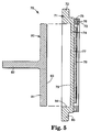
- FIG 5 illustrates a quick-mounting fastening assembly 70 which, like the fastening assemblies 30 and 50 illustrated in Figures 3 and 4 respectively, can be easily removed after being bonded to a substrate.
- the fastening assembly 70 comprises a fastening structure 71 (which could be formed of polymeric material or metal) including a circular outer portion 72 which has an annular generally planar initial attachment surface 73 covered by a layer 75 of pressure-sensitive adhesive that preferably is a foamed or foam-like layer and is protected by a removable release liner 76.
- the fastening structure 71 also includes an inner portion 74 that has a main attachment surface 77 covered by a layer 78 of hot-melt adhesive that is slightly recessed with respect to the face of the layer 75 of pressure-sensitive adhesive, and a generally planar friction surface 79 opposite and generally parallel to its main attachment surface 77.
- the inner portion 74 has a thin cross sectional area adapted to conduct heat energy between the friction surface 79 and the main attachment surface 77.
- the fastening structure 71 has a socket 84 defined by its surfaces including the friction surface 79.
- the release liner 76 is removed and the layer 75 of pressure-sensitive adhesive is pressed against a flat surface of the substrate.
- the fastening assembly 70 can then be firmly attached to the substrate using a tool such as the tool 80 illustrated which includes a disk 81 from which projects a coaxial cylindrical shank 82 that can be received and fixed in a chuck of a rotary driving tool.
- a flat circular friction surface 83 of the tool can be pressed into contact with the friction surface 79 of the inner portion 74 while the disk 81 is rotated to generate frictional heat that is transmitted through the inner portion 74 to melt and adhere the hot-melt adhesive layer 78 to the substrate after rotation of the disk 81 is stopped and the hot melt adhesive is again allowed to solidify.
- the outer portion 72 comprises a flange 85 projecting radially outwardly of the outer periphery of the initial attachment surface 73.
- the flange 85 is spaced from the initial attachment surface 73 and the outer portion has a peripheral surface between the flange 85 and the outer periphery of the initial attachment surface 73 adapted to receive means for engaging the fastening assembly to seat various implements after the fastening assembly 70 has been mounted on a substrate.
- Each of the fastening assemblies 30, 50 and 70 illustrated in Figures 3, 4 and 5, respectively, can be removed from a substrate by using a rotary tool to generate heat in the manner described above until the hot-melt adhesive softens.
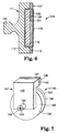
- FIG. 6 illustrates an embodiment of a quick-mounting fastening assembly according to the present invention generally designated by the reference numeral 110.
- the fastening assembly 110 includes a fastening structure 111 including a generally circular outer portion 112 which has an annular generally planar main attachment surface 113 and a central cylindrical socket 115 opening through the surface 113. Covering the main attachment surface 113 is an annular layer 117 of hot-melt adhesive. Coaxially positioned within the socket 115 is a generally cylindrical inner portion 120 of the fastening structure 111 that can be totally encompassed by the outer portion 112.
- the inner portion 120 has a planar initial attachment surface 121 that is approximately coplanar with the main attachment surface 113 and faces in the same direction as the main attachment surface 113.
- the initial attachment surface 121 is covered by a layer 122 of pressure sensitive adhesive that preferably is a foamed or foam-like layer and is protected by a removable release liner 118.
- the outer portion 112 also includes a stud-like part 124 projecting from the side of the outer portion 112 opposite its main attachment surface 113, which stud-like part 124 has a periphery with an hexagonal cross section that is coaxial with the stud-like part 124, the main attachment surface 113, and the socket 115.
- the inner portion 120 is separated from the outer portion 112, the layer 122 of pressure-sensitive adhesive (after removal of the release liner 118) is adhered at a desired location along a flat substrate, the outer portion 112 is positioned around the inner portion 120 with the exposed face of the layer 117 of hot-melt adhesive in contact with the substrate and is rotated by a rotary tool (not shown) in driving engagement with the hexagonal surface of the stud like part 124 to melt the layer 117 of hot-melt adhesive. As soon as the layer 117 of hot-melt adhesive melts, the tool is stopped, and the layer 117 of melted hot-melt adhesive quickly congeals or solidifies to bond the fastening assembly 110 to the substrate. Any of a variety of devices such as a flexible clip that can retain cables, wires, cords, and the like can then be attached to the peripheral surface and/or the stud like part 124 of the outer portion 112.
- FIG. 7 illustrates a quick-mounting fastening assembly 140 according to the present invention that includes a fastening structure 141.
- the fastening structure 141 includes a generally L-shaped outer portion 142 which has a generally rectangular planar initial attachment surface 143 at the distal end of one leg and a transverse opening 145 through it's other leg. Covering the attachment surface 143 is a layer 147 of pressure-sensitive adhesive that preferably is a foamed or foam-like layer and is protected by a removable release liner 148.
- a generally cylindrical stud-like part 154 of an inner portion 150 of the fastening structure 141 that coaxially projects from the side of a disk-shaped part 149 of that inner portion 150.
- the disk-shaped part 149 of the inner portion 150 has a planar main attachment surface 151 on its side opposite the stud-like part 154 that is approximately co-planar with the initial attachment surface 143 and faces in the same direction as the initial attachment surface 143.
- the main attachment surface 151 is covered by a layer 152 of hot-melt adhesive.
- the stud-like part 154 is rotatable within the outer portion 142 and has a socket 155 shaped to receive the tip of a "Phillips" type screw driver (not shown) that is coaxial with the stud-like part 154.
- the layer 147 of pressure-sensitive adhesive (after removal of the release liner 148) is pressed against and thereby adhered to a flat substrate, and the exposed face of the layer 152 of hot-melt adhesive is pushed into full contact with and rotated against the substrate by a rotary tool (not shown) in driving engagement in the socket 155 until the layer 152 of hot-melt adhesive melts.
- the tool is then stopped, whereupon the layer 152 of melted hot-melt adhesive quickly solidifies to bond the fastening assembly 140 to the substrate.
- the outer portion 142 or the stud-like part 154 can then be releasably engaged by any of a variety of devices such as a flexible clip that can retain cables, wires, cords, and the like.
- FIGs 8 and 9 illustrate a quick-mounting fastening assembly 170 which, like the fastening assemblies 30, 50 and 70 illustrated in Figures 3, 4 and 5 respectively, can be easily removed after being bonded to a substrate.
- the fastening assembly 170 comprises a fastening structure 171 including a circular portion 172 which has a generally planar initial attachment surface 173 covered by a layer 175 of pressure-sensitive adhesive that preferably is a foamed or foam-like layer and can be protected by a removable release liner (not shown), and a main attachment surface 177 covered by a layer 178 of hot-melt adhesive, and a generally planar friction surface 179 opposite and generally parallel to its main attachment surface 177.
- the circular portion 172 has a thin cross sectional area adapted to conduct heat energy between the friction surface 179 and the main attachment surface 177.
- the fastening structure 171 has a socket 170 defined by its surfaces including the friction surface 179.
- the release liner is removed and the layer 175 of pressure-sensitive adhesive is pressed against a flat surface of the substrate.
- the fastening assembly 170 can then be firmly attached to the substrate using a tool such as the tool 80 illustrated in Figure 5 by pressing the friction surface 83 of the tool 80 into contact with the friction surface 179 while the disk 81 is rotated to generate frictional heat that is transmitted through the inner portion 174 to melt and adhere the hot-melt adhesive layer 178 to the substrate after rotation of the disk 81 is stopped and the layer 178 of hot melt adhesive is again allowed to solidify.
- the fastening structure 171 includes a semi-circular rib 181 around the periphery of the layer 178 of hot melt adhesive that with the layer 175 of pressure sensitive adhesive provides a damn to retain the layer 178 of melt adhesive along the main attachment surface 177 when it is melted during application of the fastening assembly 170.
- the fastening structure 171 also comprises a flange 185 projecting radially outwardly of the outer periphery of the surface 173.
- the flange 185 is spaced from the initial and main attachment surfaces 173 and 177 and the fastening structure 171 has a peripheral surface between the flange 185 and the outer periphery of those surfaces 173 and 177 adapted to receive means for engaging the fastening assembly to seat various implements after the fastening assembly 170 has been mounted on a substrate.
- the fastening assembly 170 can be removed from a substrate to which it has been attached by using the rotary tool 80 to generate heat in the manner described above until the layer 178 of hot-melt adhesive softens.
- Fastening assemblies according to the present invention were tested by mounting them onto a vertical concrete barrier.
- the inner portion of the novel fastening structure was a rotatable disk (as in Figures 1 and 2 of the drawing) bearing a typical hot-melt adhesive, the adhesive fused within three seconds by driving the disk with an ordinary household drill.
- the inner portion was of aluminum as in Figure 4 of the drawing, a typical hot-melt adhesive fused within five seconds.
- the inner portion was of polymeric material (as in Figures 3 and 5 of the drawing) and had a thickness of about 0.75 mm (0.030 inch), a typical hot-melt adhesive fused within ten seconds.
- each fastening assembly had become securely bonded to the wall and could not be knocked loose without destroying the surface of the wall. Hence, each could be put to immediate use to support or mount articles such as a fixture, a picture, garments, or a conduit.
- a fastening assembly according to the present invention has a polymeric inner portion that separates the hot-melt adhesive from a rotatable disk (as in the fastening assembly 30 of Figure 3 or in the fastening assembly 70 of Figure 5), insufficient heat can be conducted through the inner portion to degrade the hot-melt adhesive, no matter how long the spinning continues. However, care should be employed not to continue the spinning to the point of damaging the inner portion.
Landscapes
- Engineering & Computer Science (AREA)
- Mechanical Engineering (AREA)
- General Engineering & Computer Science (AREA)
- Adhesives Or Adhesive Processes (AREA)
- Standing Axle, Rod, Or Tube Structures Coupled By Welding, Adhesion, Or Deposition (AREA)
Abstract
Claims (20)
- Ensemble de fixation à montage rapide (10, 30, 50, 70, 110, 140, 170) comportant :une structure de fixation (11, 31, 51, 71, 111, 141, 171) ayant une surface de fixation initiale (13, 33, 53, 73, 121, 143, 173) et une surface de fixation principale (21, 37, 57, 77, 113, 151, 177) qui est approximativement coplanaire à ladite surface de fixation initiale (13, 33, 53, 73, 121, 143, 173) ;une couche (17, 35, 55, 75, 122, 147, 175) d'adhésif sensible à la pression située sur ladite surface de fixation initiale (13, 33, 53, 73, 121, 143, 173) qui permet de coller la structure de fixation (11, 31, 51, 71, 111, 141, 171) sur une surface d'un substrat en appuyant la couche (17, 35, 55, 75, 122, 147, 175) d'adhésif sensible à la pression contre le substrat ;une couche (22, 38, 58, 78, 117, 152, 178) d'adhésif thermofusible située sur ladite surface de fixation principale (21, 37, 57, 77, 113, 151, 177) ; etdes moyens de chauffage par friction destinés à permettre un chauffage par friction suffisant pour faire fondre la couche (22, 38, 58, 78, 117, 152, 178) d'adhésif thermofusible, la couche (17, 35, 55, 75, 122, 147, 175) d'adhésif sensible à la pression étant collée sur un substrat de sorte que lorsqu'elle se solidifie de nouveau, la couche (22, 38, 58, 78, 117, 152, 178) d'adhésif thermofusible sera collée sur le substrat.
- Ensemble de fixation (10, 30, 50, 70) selon la revendication 1, dans lequel ladite structure de fixation (11, 31, 51, 71) comporte une partie intérieure (20, 34, 54, 74) ayant ladite surface de fixation principale (21, 37, 57, 77) ; et une partie extérieure (12, 32, 52, 72) ayant ladite surface de fixation initiale (13, 33, 53, 73), ladite surface de fixation initiale (13, 33, 53, 73) entourant ladite surface de fixation principale (21, 37, 57, 77).
- Ensemble de fixation (10) selon la revendication 2, dans lequel ladite partie extérieure (12) a une ouverture circulaire traversante ; ladite partie intérieure (20) est de manière générale circulaire autour d'un axe perpendiculaire à ladite surface de fixation principale (21) ; lesdites parties intérieure et extérieure (20 ; 12) comportent des moyens de montage de ladite partie intérieure (20) pour qu'elle tourne dans ladite partie extérieure (12), et lesdits moyens de chauffage par friction comportent des moyens de prise d'entraínement agencés sur ladite partie intérieure (20) pour relier de manière libérable ladite partie intérieure (20) à une source d'énergie de rotation pour faire tourner ladite partie intérieure (20) autour dudit axe, ladite couche (22) d'adhésif thermofusible étant en contact avec ladite surface de substrat pour faire fondre ladite couche (22) d'adhésif thermofusible.
- Ensemble de fixation (10) selon la revendication 3, dans lequel lesdits moyens de prise d'entraínement comportent des surfaces de ladite partie intérieure (20) définissant une douille (25) formée pour recevoir de manière serrée l'extrémité d'un élément d'entraínement, ladite douille (25) étant coaxiale à ladite partie intérieure (20) et ouvrant à travers le côté de ladite partie intérieure (20) opposé à ladite surface de fixation principale (21).
- Ensemble de fixation (10) selon la revendication 3, dans lequel ladite partie intérieure (20) comporte une partie analogue à un picot (24) faisant saillie coaxialement sur un côté de ladite partie intérieure (20) opposé à ladite surface de fixation principale (21) au-delà de ladite partie extérieure (12), et lesdits moyens de prise d'entraínement (25) sont formés sur ladite partie analogue à un picot (24).
- Ensemble de fixation (10) selon la revendication 3, dans lequel ladite surface de fixation initiale (13) est annulaire et a une périphérie extérieure, et ladite partie extérieure (12) comporte un rebord (23) faisant saillie radialement vers l'extérieur de la périphérie extérieure de ladite surface de fixation initiale (13), ledit rebord (23) étant espacé de ladite surface de fixation initiale (13) et ladite partie extérieure (12) ayant une surface périphérique située entre ledit rebord (23) et la périphérie extérieure de ladite surface de fixation initiale (13) adaptée pour recevoir des moyens destinés à venir en prise avec l'ensemble de fixation (10).
- Ensemble de fixation (30, 50) selon la revendication 2, dans lequel ladite partie intérieure (34, 54) a une surface de friction (39, 59) de manière générale plane, opposée de manière générale parallèlement à ladite surface de fixation principale (37, 57), ladite partie intérieure (34, 54) a une section transversale adaptée pour conduire l'énergie thermique entre ladite surface de friction (39, 59) et ladite surface de fixation principale (37, 57), ladite structure de fixation (31, 51) a une douille (40, 60) définie par des surfaces y compris ladite surface de friction (39, 59), et ledit ensemble de fixation (30, 50) comporte de plus un disque de friction (41, 61) ayant une surface de friction plane (42, 62), des moyens de montage dudit disque de friction (41, 61) dans ladite douille (40, 60), lesdites surfaces de friction (39, 59 ; 42, 62) étant adjacentes pour tourner autour d'un axe perpendiculaire auxdites surfaces de friction (39, 59 ; 42, 62), et des moyens de prise d'entraínement (43, 63) situés sur ledit disque de friction (41, 61) pour relier de manière libérable ledit disque de friction (41, 61) à une source d'énergie de rotation pour entraíner en rotation ledit disque de friction (41, 61) autour dudit axe, lesdites surfaces de friction (39, 59 ; 42, 62) étant en contact pour chauffer ladite partie intérieure (34, 54) et ainsi faire fondre ladite couche (38, 58) d'adhésif thermofusible par transfert de chaleur à travers ladite partie intérieure (34, 54).
- Ensemble de fixation (50) selon la revendication 7, dans lequel ladite partie intérieure (54) comporte du métal.
- Ensemble de fixation (30) selon la revendication 7, dans lequel ladite partie intérieure (34) comporte un matériau polymérique résistant à la chaleur.
- Ensemble de fixation (30) selon la revendication 7, dans lequel lesdits moyens de prise d'entraínement comportent des surfaces dudit disque de friction (41) définissant une douille (43) formée pour recevoir de manière serrée l'extrémité d'un tournevis Phillips, ladite douille (43) étant coaxiale audit disque (41) et ouvrant à travers le côté dudit disque (41) opposé auxdites surfaces de friction (39 ; 42).
- Ensemble de fixation (50) selon la revendication 7, dans lequel ledit disque de friction (61) comporte une partie analogue à un picot (66) faisant saillie coaxialement sur le côté dudit disque (61) opposé auxdites surfaces de friction (59 ; 62) au-delà desdites parties intérieure et extérieure (54 ; 52), et lesdits moyens de prise d'entraínement sont formés sur ladite partie analogue à un picot (66).
- Ensemble de fixation (30) selon la revendication 7, dans lequel ladite surface de fixation initiale (33) est annulaire et a une périphérie extérieure, et ladite partie extérieure (32) comporte un rebord (46) faisant saillie radialement vers l'extérieur de la périphérie extérieure de ladite surface de fixation initiale (33), ledit rebord (46) étant espacé de ladite surface de fixation initiale (33) et ladite partie extérieure (32) ayant une surface périphérique située entre ledit rebord (46) et la périphérie extérieure de ladite surface de fixation initiale (33) adaptée pour recevoir des moyens destinés à venir en prise avec l'ensemble de fixation (30).
- Ensemble de fixation (70) selon la revendication 2, dans lequel ladite partie intérieure (74) a une surface de friction (79) de manière générale plane opposée et de manière générale parallèle à ladite surface de fixation principale (77), ladite partie intérieure (74) est constituée d'un matériau stable à la chaleur et a une section transversale adaptée pour conduire l'énergie thermique entre ladite surface de friction (79) et ladite surface de fixation principale (77), et ladite structure de fixation (71) a une douille (84) définie par des surfaces y compris ladite surface de friction (79), adaptée pour recevoir et avoir un disque de friction (81) ayant une surface de friction plane (83) entraínée en rotation dans celle-ci, ladite surface de friction plane (83) située sur ledit disque de friction (81) étant en contact avec ladite surface de friction (79) de ladite partie intérieure (74) pour chauffer et ainsi faire fondre ladite couche (78) d'adhésif thermofusible par transfert de chaleur à travers ladite partie intérieure (74).
- Ensemble de fixation (70) selon la revendication 13, dans lequel ladite partie intérieure (74) comporte un matériau polymérique résistant à la chaleur.
- Ensemble de fixation (70) selon la revendication 13, dans lequel ladite surface de fixation initiale (73) est annulaire et a une périphérie extérieure, et ladite partie extérieure (72) comporte un rebord (85) faisant saillie radialement vers l'extérieur de la périphérie extérieure de ladite surface de fixation initiale (73), ledit rebord (85) étant espacé de ladite surface de fixation initiale (73) et ladite partie extérieure (72) a une surface périphérique située entre ledit rebord (85) et la périphérie extérieure de ladite surface de fixation initiale (73) adaptée pour recevoir des moyens destinés à venir en prise avec l'ensemble de fixation (70).
- Ensemble de fixation (10) selon la revendication 1, dans lequel ladite structure de fixation (11) comporte une partie principale (20) ayant ladite surface de fixation principale (21), et une partie extérieure (12) ayant ladite surface de fixation initiale (13) ; ladite partie extérieure (12) a une ouverture circulaire traversante ; ladite partie principale (20) est de manière générale circulaire autour d'un axe perpendiculaire à ladite surface de fixation principale (21) ; lesdites parties principale et extérieure (20 ; 12) comportent des moyens destinés au montage de ladite partie principale (20) pour qu'elle tourne sur ladite partie extérieure (12), et lesdits moyens de chauffage par friction comportent des moyens de prise d'entraínement (25) situés sur ladite partie principale (20) pour relier de manière libérable ladite partie principale (20) à une source d'énergie de rotation pour faire tourner ladite partie principale (20) autour dudit axe, ladite couche (22) d'adhésif thermofusible étant en contact avec ladite surface de substrat pour faire fondre ladite couche (22) d'adhésif thermofusible.
- Ensemble de fixation (10) selon la revendication 16, dans lequel lesdits moyens de prise d'entraínement comportent des surfaces de ladite partie principale (20) définissant une douille (25) formée pour recevoir de manière serrée l'extrémité d'un élément d'entraínement, ladite douille (25) étant coaxiale à ladite partie principale (20) et ouvrant à travers le côté de ladite partie principale (20) opposé à ladite surface de fixation principale (21).
- Ensemble de fixation (10) selon la revendication 16, dans lequel ladite partie principale (20) comporte une partie analogue à un picot (24) faisant saillie coaxialement sur le côté de ladite partie principale (20) opposé à ladite surface de fixation principale (21) au-delà de ladite partie extérieure (12), et lesdits moyens de prise d'entraínement (25) sont formés sur ladite partie analogue à un picot (24).
- Ensemble de fixation (110) selon la revendication 1, dans lequel ladite structure de fixation (111) comporte une partie intérieure (120) ayant ladite surface de fixation initiale (121) ; et une partie extérieure (112) ayant ladite surface de fixation principale (113) ; ladite partie extérieure (112) a une douille (115) ouvrant à travers ladite surface de fixation principale (113) ; ladite partie extérieure (112) est de manière générale annulaire autour d'un axe perpendiculaire à ladite surface de fixation principale (113) ; ladite partie extérieure (112) est adaptée pour tourner autour de ladite partie intérieure (120), ladite partie intérieure (120) de ladite douille (115), et lesdits moyens de chauffage par friction comportent des moyens de prise d'entraínement sur ladite partie extérieure (112) pour relier de manière libérable ladite partie extérieure (112) à une source d'énergie de rotation pour faire tourner ladite partie extérieure (112) autour dudit axe, ladite couche (117) d'adhésif thermofusible étant en contact avec ladite surface de substrat pour faire fondre ladite couche (117) d'adhésif thermofusible.
- Ensemble de fixation (70, 170) selon la revendication 1, dans lequel ladite structure de fixation (71, 171) a une surface de friction (79, 179) de manière générale plane opposée, et de manière générale parallèle à ladite surface de fixation principale (77, 177), qui est constituée d'un matériau stable à la chaleur et qui est adaptée pour conduire l'énergie thermique entre ladite surface de friction (79, 179) et ladite surface de fixation principale (77, 177), et a une douille (84), définie par des surfaces y compris ladite surface de friction (79, 179), adaptée pour recevoir et avoir un disque de friction (81) ayant une surface de friction plane (83) entraínée en rotation dans celle-ci, la surface de friction plane (83) dudit disque de friction (81) étant en contact avec ladite surface de friction (79, 179) de ladite structure de fixation (71, 171) pour chauffer et ainsi faire fondre ladite couche (78, 178) d'adhésif thermofusible par transfert de chaleur à travers ladite structure de fixation (71, 171).
Applications Claiming Priority (3)
| Application Number | Priority Date | Filing Date | Title |
|---|---|---|---|
| US08/342,715 US5593120A (en) | 1994-11-21 | 1994-11-21 | Quick-mounting fastening assembly |
| PCT/US1995/013210 WO1996015897A1 (fr) | 1994-11-21 | 1995-10-17 | Element de fixation a montage rapide |
| US342715 | 1999-06-29 |
Publications (2)
| Publication Number | Publication Date |
|---|---|
| EP0793571A1 EP0793571A1 (fr) | 1997-09-10 |
| EP0793571B1 true EP0793571B1 (fr) | 1998-09-30 |
Family
ID=23342970
Family Applications (1)
| Application Number | Title | Priority Date | Filing Date |
|---|---|---|---|
| EP95936334A Expired - Lifetime EP0793571B1 (fr) | 1994-11-21 | 1995-10-17 | Element de fixation a montage rapide |
Country Status (6)
| Country | Link |
|---|---|
| US (1) | US5593120A (fr) |
| EP (1) | EP0793571B1 (fr) |
| JP (1) | JPH10510032A (fr) |
| CA (1) | CA2203644C (fr) |
| DE (1) | DE69505150T2 (fr) |
| WO (1) | WO1996015897A1 (fr) |
Cited By (1)
| Publication number | Priority date | Publication date | Assignee | Title |
|---|---|---|---|---|
| FR3123095A1 (fr) | 2021-05-18 | 2022-11-25 | Jean-Christophe HABOT | Système de fixation multi-support compact déporté |
Families Citing this family (52)
| Publication number | Priority date | Publication date | Assignee | Title |
|---|---|---|---|---|
| BR9608808A (pt) * | 1995-05-26 | 1999-02-17 | Henkel Kgaa | Processos de cola |
| JP2803034B2 (ja) * | 1995-11-27 | 1998-09-24 | ホクメイ株式会社 | 保持具および保持具の取付方法 |
| US5931729A (en) * | 1997-04-15 | 1999-08-03 | Minnesota Mining And Manufacturing Company | Article made by spin welding a fastener thereto |
| FR2784359B1 (fr) * | 1998-10-07 | 2004-03-12 | Rapid Sa | Bouchon d'obturation thermocollant et autocollant |
| US6153035A (en) * | 1999-02-12 | 2000-11-28 | The Boeing Company | Method and apparatus for securing a thermoplastic insert within a sandwich panel |
| US6899137B2 (en) * | 1999-06-28 | 2005-05-31 | California Institute Of Technology | Microfabricated elastomeric valve and pump systems |
| DE60025736T2 (de) * | 2000-04-18 | 2006-11-09 | 3M Innovative Properties Co., Saint Paul | Verfahren zum anbringen eines befestigungselements auf einem oberflächenbehandelungsgegenstand und damit hergestellter gegenstand |
| EP1170431A1 (fr) * | 2000-07-04 | 2002-01-09 | Max Co., Ltd. | Dispositif de collage et système de montage des plaques de plâtre |
| US7575208B2 (en) * | 2003-10-27 | 2009-08-18 | Yung-Huei Lan | Holding device with a securing sheet for mounting onto a wall |
| US6641105B1 (en) * | 2000-11-06 | 2003-11-04 | 3M Innovative Properties Company | Hanger |
| US6679667B2 (en) | 2001-02-28 | 2004-01-20 | Northrop Grumman Corporation | Hot melt fastener filler |
| US20030147714A1 (en) * | 2002-02-05 | 2003-08-07 | Yu Yuan Liang | Metal plane jointing structure and making method thereof |
| US20030170450A1 (en) * | 2002-03-05 | 2003-09-11 | Stewart Steven L. | Attachment of surface mount devices to printed circuit boards using a thermoplastic adhesive |
| EP1396385B1 (fr) * | 2002-09-05 | 2008-04-23 | Siemens Aktiengesellschaft | Ensemble pour fixer par collage un appareil ou un support d'appareil sur une embase |
| JP4328229B2 (ja) * | 2003-06-04 | 2009-09-09 | 株式会社ユニオン精密 | ねじ付属品を用いた締結体構造及びねじ付属品を用いた解体方法 |
| US7150100B2 (en) * | 2004-07-09 | 2006-12-19 | Armstrong International, Inc. | Method of forming a jacketed steam distribution tube |
| GB0508275D0 (en) * | 2005-04-25 | 2005-06-01 | Visual Edge Ltd | Fastening system |
| DE102005041350A1 (de) * | 2005-08-31 | 2007-03-01 | Ejot Gmbh & Co. Kg | Mit einem Loch einer Platte fluchtendes Mutterteil für ein Befestigungsmittel |
| US20070096003A1 (en) * | 2005-11-03 | 2007-05-03 | Kuo Liao Hsiu-Mei | Sticker type wall surface holder |
| US7645105B2 (en) * | 2006-06-27 | 2010-01-12 | Gm Global Technology Operations, Inc. | Projection welded fastener with integral sealer |
| JP5099548B2 (ja) * | 2007-12-03 | 2012-12-19 | 学校法人東海大学 | 締結体構造 |
| GB2457038B (en) * | 2008-01-30 | 2011-10-12 | Gareth Phillips | Fixing |
| GB2482737B (en) * | 2010-08-13 | 2016-05-25 | Croydex Ltd | Kit and method for assembling a mounting |
| DE102010056221A1 (de) * | 2010-12-24 | 2012-06-28 | Friederike Ortwein | Befestiger |
| US8616868B2 (en) * | 2011-02-28 | 2013-12-31 | Physical Systems, Inc. | Sealant mold fixture for a domed cap |
| US8602764B2 (en) * | 2011-02-28 | 2013-12-10 | Physical Systems, Inc. | Sealant mold fixture for a dome element |
| JP5360921B2 (ja) * | 2011-04-21 | 2013-12-04 | Dipperホクメイ株式会社 | 粘着式の固着具、およびその固着方法、および粘着式の固着具を備えている手摺構造 |
| EP2520419A1 (fr) * | 2011-05-02 | 2012-11-07 | Lammhults Möbel AB | Soudure par friction |
| US20130146625A1 (en) * | 2011-12-13 | 2013-06-13 | Bryan Karle | Attachable holder with flexible ring for any handheld device |
| DE102012000353A1 (de) * | 2012-01-11 | 2013-07-11 | H.A. Springer marine + industrie service GmbH | Verfahren zum Aufkleben eines Befestigungselements auf ein Trägerbauteil eines Automobils und Befestigungselement |
| US20140017459A1 (en) * | 2012-07-10 | 2014-01-16 | Nike, Inc. | Temporarily Positionable Meltable Adhesives For Shoe And Apparel Assembly |
| US20140017458A1 (en) | 2012-07-10 | 2014-01-16 | Nike, Inc. | Temporarily Positionable Meltable Adhesives For Shoe And Apparel Assembly |
| US9049929B2 (en) | 2013-01-31 | 2015-06-09 | A. Raymond Et Cie | Appliance apparatus including a bonded bracket |
| EP2781765A1 (fr) * | 2013-03-20 | 2014-09-24 | Sulzer Mixpac AG | Elément de fixation destiné à être accroché à un mur |
| DE102013011536A1 (de) * | 2013-07-10 | 2015-01-15 | Sfs Intec Holding Ag | Positioniervorrichtung und Verfahren zum Aufkleben eines Objekts auf einer Oberfläche |
| US9849637B2 (en) * | 2013-10-22 | 2017-12-26 | The Boeing Company | Self-centering sealant applicator |
| US10925417B2 (en) | 2014-01-22 | 2021-02-23 | Ccl Label, Inc. | Secure hold hook |
| US9296319B2 (en) * | 2014-02-20 | 2016-03-29 | Solomon J. Orona | Arm support |
| US10694820B2 (en) | 2014-05-13 | 2020-06-30 | Wrdt, Llc | Attachment device |
| CN104048148A (zh) * | 2014-06-17 | 2014-09-17 | 仲杏英 | 热熔固定基座 |
| WO2015195344A1 (fr) | 2014-06-17 | 2015-12-23 | 3M Innovative Properties Company | Support d'article utilisant des adhésifs à libération par décollement |
| AU2016243322B2 (en) * | 2015-03-27 | 2019-02-28 | 3M Innovative Properties Company | Canvas mounting device |
| US10737423B2 (en) | 2015-08-28 | 2020-08-11 | The Boeing Company | Systems and methods for sealant injection molding |
| CN105433733A (zh) * | 2015-12-31 | 2016-03-30 | 品顶实业有限公司 | 挂钩装置及具有该挂钩装置的挂钩组合件 |
| EP3225856B1 (fr) * | 2016-03-30 | 2018-11-28 | Aufrecht GmbH | Dispositif de fixation |
| KR101979598B1 (ko) * | 2016-08-09 | 2019-05-17 | 장진태 | 흡착 장치 |
| US10352345B2 (en) * | 2016-12-05 | 2019-07-16 | The Boeing Company | Adhesive-bonded attachment device |
| US10378569B2 (en) | 2017-10-25 | 2019-08-13 | Caterpillar Inc. | Adhesive based mounting structure |
| US11178986B2 (en) * | 2017-11-28 | 2021-11-23 | Darren Mark Maynard | Positioning and stabilizing device for picture frames and the like |
| EP3872144A1 (fr) * | 2020-02-26 | 2021-09-01 | fischerwerke GmbH & Co. KG | Éléments de matière adhésive pouvant être activés par chaleur de friction destinés à la fixation des objets |
| CN111288059B (zh) * | 2020-03-18 | 2024-02-09 | 博众精工科技股份有限公司 | 一种压合平面自适应压合设备、一种液晶屏的压合方法 |
| EP4197747B1 (fr) * | 2021-12-15 | 2024-03-13 | Volvo Car Corporation | Partie de connexion pour un processus d'assemblage industriel, connexion de partie et procédé de connexion par adhésion d'une partie de connexion et d'une partie d'accouplement |
Family Cites Families (24)
| Publication number | Priority date | Publication date | Assignee | Title |
|---|---|---|---|---|
| US2385296A (en) * | 1944-05-19 | 1945-09-18 | Goodloe E Moore | Cementitious anchorable hanger support |
| US2765998A (en) * | 1950-06-14 | 1956-10-09 | Poster Products Inc | Supporting device |
| DE1297322B (de) * | 1963-11-21 | 1969-06-12 | Flax V | Vorrichtung zum Verbinden von rohrfoermigen, thermoplastischen oder mit derartigem Werkstoff beschichteten Kunststoffteilen durch Reibungsschweissen |
| FR1407064A (fr) * | 1963-11-21 | 1965-07-30 | Procédé et outillage pour solidariser plusieurs pièces en matière thermosoudable | |
| US3300173A (en) * | 1965-05-11 | 1967-01-24 | Jr Merritt T Kennedy | Picture hangers and nail withdrawal tools for use in connection therewith |
| US3468732A (en) * | 1966-08-19 | 1969-09-23 | Uniroyal Inc | Method of butt joining thermoplastic sheet material by a spin welding operation |
| US3689334A (en) * | 1970-09-14 | 1972-09-05 | Esb Inc | Method of bonding metal to polymers with melt adhesive |
| US3866873A (en) * | 1972-06-16 | 1975-02-18 | Us Navy | Adhesive-fastened padeye device |
| US3848843A (en) * | 1972-08-03 | 1974-11-19 | Selfix Inc | Fixture assembly |
| FR2252913A1 (en) * | 1973-11-29 | 1975-06-27 | Flax V | Process for annular welding of thermoplastic components - using an intermediate metal cap to transfer heat |
| US4338151A (en) * | 1979-09-13 | 1982-07-06 | Physical Systems, Inc. | Method of securing an adhesive attachment assembly to a substrate |
| US4390576A (en) * | 1980-09-19 | 1983-06-28 | Physical Systems, Inc. | Adhesive attachment assembly |
| DE3108972A1 (de) * | 1981-03-10 | 1982-09-23 | Steuler Industriewerke GmbH, 5410 Höhr-Grenzhausen | Verfahren zur herstellung von grossflaechigen, als verlorene schalung einsetzbaren auskleidungsplatten |
| US4477307A (en) * | 1982-12-06 | 1984-10-16 | Illinois Tool Works Inc. | Friction welded fastener system |
| JPS6065082A (ja) * | 1983-09-21 | 1985-04-13 | Nifco Inc | スタツドのワ−クに対する固定方法 |
| US4551189A (en) * | 1984-12-12 | 1985-11-05 | Illinois Tool Works Inc. | Friction welded fastener system |
| US4636124A (en) * | 1985-05-06 | 1987-01-13 | Illinois Tool Works Inc. | Adhesive friction weld fastener |
| US4822656A (en) * | 1985-09-04 | 1989-04-18 | Physical Systems, Inc. | Fixture for securing an adhesive attachment to a substrate |
| US4842912A (en) * | 1985-09-04 | 1989-06-27 | Physical Systems, Inc. | Adhesive attachment and mounting fixture |
| US4778702A (en) * | 1985-09-04 | 1988-10-18 | Physical Systems, Inc. | Adhesive attachment and mounting fixture |
| JPS6328632A (ja) * | 1986-07-23 | 1988-02-06 | Nifco Inc | 樹脂製回転溶着部材 |
| US4822224A (en) * | 1987-11-05 | 1989-04-18 | Chrysler Motors Corporation | Harness retainer stud |
| US4923159A (en) * | 1988-12-22 | 1990-05-08 | Wang Hsug Fang | Hook seat with a separable hook |
| JPH02248236A (ja) * | 1989-03-22 | 1990-10-04 | Haruhisa Sugiyama | プラスチック接合スタッド |
-
1994
- 1994-11-21 US US08/342,715 patent/US5593120A/en not_active Expired - Lifetime
-
1995
- 1995-10-17 WO PCT/US1995/013210 patent/WO1996015897A1/fr active IP Right Grant
- 1995-10-17 EP EP95936334A patent/EP0793571B1/fr not_active Expired - Lifetime
- 1995-10-17 DE DE69505150T patent/DE69505150T2/de not_active Expired - Fee Related
- 1995-10-17 JP JP8516838A patent/JPH10510032A/ja not_active Ceased
- 1995-10-17 CA CA002203644A patent/CA2203644C/fr not_active Expired - Fee Related
Cited By (1)
| Publication number | Priority date | Publication date | Assignee | Title |
|---|---|---|---|---|
| FR3123095A1 (fr) | 2021-05-18 | 2022-11-25 | Jean-Christophe HABOT | Système de fixation multi-support compact déporté |
Also Published As
| Publication number | Publication date |
|---|---|
| WO1996015897A1 (fr) | 1996-05-30 |
| CA2203644A1 (fr) | 1996-05-30 |
| EP0793571A1 (fr) | 1997-09-10 |
| US5593120A (en) | 1997-01-14 |
| JPH10510032A (ja) | 1998-09-29 |
| DE69505150T2 (de) | 1999-06-02 |
| CA2203644C (fr) | 2007-01-09 |
| DE69505150D1 (de) | 1998-11-05 |
Similar Documents
| Publication | Publication Date | Title |
|---|---|---|
| EP0793571B1 (fr) | Element de fixation a montage rapide | |
| US4566924A (en) | Method for fixing stud on workpiece | |
| US4477307A (en) | Friction welded fastener system | |
| US4676707A (en) | Friction welded fastener system | |
| US5725341A (en) | Self fusing fastener | |
| US5085655A (en) | Cohesive tape system | |
| EP1587891B1 (fr) | Ensemble de fixation adhesif comportant une source de chaleur | |
| JPH0378057B2 (fr) | ||
| US4657626A (en) | Friction welding tool | |
| EP0340990A3 (fr) | Adhésif thermofusible, résistant au fluage et à bon délai de prise à température ambiante | |
| EP1276594B1 (fr) | Procede de fixation d'une attache a un element de traitement de surface et article dote de ladite attache | |
| JP3739458B2 (ja) | 留め具及びその留め具に連結される保持具 | |
| EP0469714A1 (fr) | Dispositif pour attacher des couches d'isolation de façon amovible | |
| EP0112074A1 (fr) | Système de fixation soudé par frottement, élément de fixation et outil à cet effet | |
| JP3986749B2 (ja) | 物品取付具 | |
| JPH0370042B2 (fr) | ||
| JPH0532278Y2 (fr) | ||
| JP3072000U (ja) | 掛止具 | |
| JPH07108552B2 (ja) | 回転溶着部材 | |
| JP3003563U (ja) | 係止具 | |
| JPS6027522A (ja) | プラスチツクスタツドのワ−クに対する固定方法 | |
| JPS5828349A (ja) | 管端面部の被覆方法 | |
| JP2523313B2 (ja) | 樹脂製回転溶着部材 | |
| JPH05254021A (ja) | 摩擦溶接の方向付けシステム | |
| JPS6213824A (ja) | 自在継手のブ−ツ組立法及びブ−ツ |
Legal Events
| Date | Code | Title | Description |
|---|---|---|---|
| PUAI | Public reference made under article 153(3) epc to a published international application that has entered the european phase |
Free format text: ORIGINAL CODE: 0009012 |
|
| 17P | Request for examination filed |
Effective date: 19970422 |
|
| AK | Designated contracting states |
Kind code of ref document: A1 Designated state(s): CH DE FR GB |
|
| 17Q | First examination report despatched |
Effective date: 19970923 |
|
| GRAG | Despatch of communication of intention to grant |
Free format text: ORIGINAL CODE: EPIDOS AGRA |
|
| GRAG | Despatch of communication of intention to grant |
Free format text: ORIGINAL CODE: EPIDOS AGRA |
|
| GRAH | Despatch of communication of intention to grant a patent |
Free format text: ORIGINAL CODE: EPIDOS IGRA |
|
| GRAH | Despatch of communication of intention to grant a patent |
Free format text: ORIGINAL CODE: EPIDOS IGRA |
|
| GRAA | (expected) grant |
Free format text: ORIGINAL CODE: 0009210 |
|
| AK | Designated contracting states |
Kind code of ref document: B1 Designated state(s): CH DE FR GB |
|
| PG25 | Lapsed in a contracting state [announced via postgrant information from national office to epo] |
Ref country code: LI Free format text: LAPSE BECAUSE OF FAILURE TO SUBMIT A TRANSLATION OF THE DESCRIPTION OR TO PAY THE FEE WITHIN THE PRESCRIBED TIME-LIMIT Effective date: 19980930 Ref country code: CH Free format text: LAPSE BECAUSE OF FAILURE TO SUBMIT A TRANSLATION OF THE DESCRIPTION OR TO PAY THE FEE WITHIN THE PRESCRIBED TIME-LIMIT Effective date: 19980930 |
|
| REG | Reference to a national code |
Ref country code: CH Ref legal event code: EP |
|
| REF | Corresponds to: |
Ref document number: 69505150 Country of ref document: DE Date of ref document: 19981105 |
|
| ET | Fr: translation filed | ||
| REG | Reference to a national code |
Ref country code: CH Ref legal event code: PL |
|
| PLBE | No opposition filed within time limit |
Free format text: ORIGINAL CODE: 0009261 |
|
| STAA | Information on the status of an ep patent application or granted ep patent |
Free format text: STATUS: NO OPPOSITION FILED WITHIN TIME LIMIT |
|
| 26N | No opposition filed | ||
| REG | Reference to a national code |
Ref country code: GB Ref legal event code: IF02 |
|
| PGFP | Annual fee paid to national office [announced via postgrant information from national office to epo] |
Ref country code: DE Payment date: 20071130 Year of fee payment: 13 |
|
| PGFP | Annual fee paid to national office [announced via postgrant information from national office to epo] |
Ref country code: GB Payment date: 20071029 Year of fee payment: 13 Ref country code: FR Payment date: 20071017 Year of fee payment: 13 |
|
| GBPC | Gb: european patent ceased through non-payment of renewal fee |
Effective date: 20081017 |
|
| REG | Reference to a national code |
Ref country code: FR Ref legal event code: ST Effective date: 20090630 |
|
| PG25 | Lapsed in a contracting state [announced via postgrant information from national office to epo] |
Ref country code: DE Free format text: LAPSE BECAUSE OF NON-PAYMENT OF DUE FEES Effective date: 20090501 |
|
| PG25 | Lapsed in a contracting state [announced via postgrant information from national office to epo] |
Ref country code: FR Free format text: LAPSE BECAUSE OF NON-PAYMENT OF DUE FEES Effective date: 20081031 |
|
| PG25 | Lapsed in a contracting state [announced via postgrant information from national office to epo] |
Ref country code: GB Free format text: LAPSE BECAUSE OF NON-PAYMENT OF DUE FEES Effective date: 20081017 |