EP0792989A1 - Scharnier - Google Patents
Scharnier Download PDFInfo
- Publication number
- EP0792989A1 EP0792989A1 EP97890033A EP97890033A EP0792989A1 EP 0792989 A1 EP0792989 A1 EP 0792989A1 EP 97890033 A EP97890033 A EP 97890033A EP 97890033 A EP97890033 A EP 97890033A EP 0792989 A1 EP0792989 A1 EP 0792989A1
- Authority
- EP
- European Patent Office
- Prior art keywords
- hinge
- pin
- hinge pin
- wing
- tab
- Prior art date
- Legal status (The legal status is an assumption and is not a legal conclusion. Google has not performed a legal analysis and makes no representation as to the accuracy of the status listed.)
- Granted
Links
- 239000011324 bead Substances 0.000 claims abstract description 8
- HCHKCACWOHOZIP-UHFFFAOYSA-N Zinc Chemical compound [Zn] HCHKCACWOHOZIP-UHFFFAOYSA-N 0.000 abstract description 2
- 238000003780 insertion Methods 0.000 abstract description 2
- 230000037431 insertion Effects 0.000 abstract description 2
- 229910052725 zinc Inorganic materials 0.000 abstract description 2
- 239000011701 zinc Substances 0.000 abstract description 2
- 238000005096 rolling process Methods 0.000 abstract 2
- 238000005266 casting Methods 0.000 abstract 1
- 235000012054 meals Nutrition 0.000 abstract 1
- 239000000463 material Substances 0.000 description 3
- 229910000831 Steel Inorganic materials 0.000 description 2
- 230000000694 effects Effects 0.000 description 2
- 239000002184 metal Substances 0.000 description 2
- 229910052751 metal Inorganic materials 0.000 description 2
- 239000010959 steel Substances 0.000 description 2
- 229910001369 Brass Inorganic materials 0.000 description 1
- 230000015572 biosynthetic process Effects 0.000 description 1
- 239000010951 brass Substances 0.000 description 1
- 238000010276 construction Methods 0.000 description 1
- 230000001419 dependent effect Effects 0.000 description 1
- 238000004512 die casting Methods 0.000 description 1
- 238000002347 injection Methods 0.000 description 1
- 239000007924 injection Substances 0.000 description 1
- 230000035515 penetration Effects 0.000 description 1
- 230000008092 positive effect Effects 0.000 description 1
- 230000002787 reinforcement Effects 0.000 description 1
- 239000007921 spray Substances 0.000 description 1
- 238000009718 spray deposition Methods 0.000 description 1
- 230000003068 static effect Effects 0.000 description 1
Images
Classifications
-
- E—FIXED CONSTRUCTIONS
- E05—LOCKS; KEYS; WINDOW OR DOOR FITTINGS; SAFES
- E05D—HINGES OR SUSPENSION DEVICES FOR DOORS, WINDOWS OR WINGS
- E05D5/00—Construction of single parts, e.g. the parts for attachment
- E05D5/02—Parts for attachment, e.g. flaps
- E05D5/04—Flat flaps
-
- E—FIXED CONSTRUCTIONS
- E05—LOCKS; KEYS; WINDOW OR DOOR FITTINGS; SAFES
- E05D—HINGES OR SUSPENSION DEVICES FOR DOORS, WINDOWS OR WINGS
- E05D11/00—Additional features or accessories of hinges
- E05D11/0018—Anti-tamper devices
-
- E—FIXED CONSTRUCTIONS
- E05—LOCKS; KEYS; WINDOW OR DOOR FITTINGS; SAFES
- E05D—HINGES OR SUSPENSION DEVICES FOR DOORS, WINDOWS OR WINGS
- E05D7/00—Hinges or pivots of special construction
- E05D7/10—Hinges or pivots of special construction to allow easy separation or connection of the parts at the hinge axis
- E05D7/1005—Hinges or pivots of special construction to allow easy separation or connection of the parts at the hinge axis by axially moving free pins, balls or sockets
-
- E—FIXED CONSTRUCTIONS
- E05—LOCKS; KEYS; WINDOW OR DOOR FITTINGS; SAFES
- E05D—HINGES OR SUSPENSION DEVICES FOR DOORS, WINDOWS OR WINGS
- E05D3/00—Hinges with pins
- E05D3/02—Hinges with pins with one pin
- E05D2003/025—Hinges with pins with one pin having three knuckles
- E05D2003/027—Hinges with pins with one pin having three knuckles the end knuckles being mutually connected
-
- E—FIXED CONSTRUCTIONS
- E05—LOCKS; KEYS; WINDOW OR DOOR FITTINGS; SAFES
- E05Y—INDEXING SCHEME ASSOCIATED WITH SUBCLASSES E05D AND E05F, RELATING TO CONSTRUCTION ELEMENTS, ELECTRIC CONTROL, POWER SUPPLY, POWER SIGNAL OR TRANSMISSION, USER INTERFACES, MOUNTING OR COUPLING, DETAILS, ACCESSORIES, AUXILIARY OPERATIONS NOT OTHERWISE PROVIDED FOR, APPLICATION THEREOF
- E05Y2900/00—Application of doors, windows, wings or fittings thereof
- E05Y2900/10—Application of doors, windows, wings or fittings thereof for buildings or parts thereof
- E05Y2900/13—Type of wing
- E05Y2900/148—Windows
Definitions
- the invention relates to a hinge, in particular a window hinge, each having a hinge part on the side and a wing, each of which comprises a hinge tab with bores for fastening screws and rolls or sleeves for a hinge pin, which rotatably connects the two hinge parts, the hinge pin securing against unauthorized removal has a pin tab that can be screwed onto the wing or stick. If such hinges are used where it is a matter of preventing penetration when the wing is closed, that is to say a safety effect, then it must be ensured that the hinges cannot be removed from the outside, nor can the hinge pin be pulled out or knocked out. If it is possible to remove the hinge pin (s), the entire sash can be easily removed from the stick.
- hinges in sheet metal or spray or Die casting in which the hinge pin has a nose projecting beyond the lateral surface, which engages in a groove or a gap in the roll or sleeve of the central hinge part.
- An axial groove or a gap is also provided in the subsequent curl or sleeve of the other engaging hinge part, the grooves or the gaps being aligned only in one rotational position, namely when the sash is open.
- the hinge pin cannot be removed with its nose.
- the execution requires the formation of grooves or gaps that are not conducive to the overall strength. In addition, the processing is expensive.
- the hinge pin Furthermore, it is known to form the hinge pin excessively long and to weld a pin tab in the end area of the pin tab, which is then screwed onto the stick or sash like the hinge tabs so that the screw heads are covered when the sash is closed.
- the disadvantage here is that the pin and the tab are made of steel or sheet steel because of the welded connection, and therefore the combination is extremely conspicuous, for example in brass hinges. A simple way of material exchange to adapt to the hinge type and Color is not possible.
- the hinge pin remains fixed against rotation.
- the invention aims to form a hinge pin that can be secured against pulling out in such a way that the additional parts in the design can be adapted to the hinge and are interchangeable.
- a hinge of the type described in the introduction in that the hinge pin has an annular bead as a stop next to one end region, which limits the insertion into the rolls or sleeves of the hinge tabs, and in that on a part of the hinge pin projecting beyond the annular bead or stop Pin tab is attachable by means of a roller or a sleeve.
- the pin tab is additionally screwed to the wing, so that the stick and wing each have two load-bearing rolls or sleeves that can be rotated by the hinge pin are connected.
- the hinge tab must be unscrewed. This is only possible when the sash is open.
- the static reinforcement of the hinges is an advantage, which has a very positive effect, for example, when there is wind load on an open wing.
- hinge pin Due to the multi-part design of the hinge pin to be secured, warehousing is possible without great effort, since the hinge pin can always remain the same and different designs only have to be available in color, material and design for the pin tabs.
- the roll or sleeve of the pin tab covers the hinge pin. This construction also makes it possible for the hinge pin to rotate in the rolls or sleeves, which results in easier opening and less wear on the material.
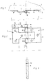
- FIG. 1 shows a hinge according to the invention from above
- Fig. 2 shows the hinge from the front
- Fig. 3 shows a hinge pin with an annular bead as a stop.
- a hinge is screwed between a stick 1 and a wing 2.
- the hinge comprises a hinge part 3 on the stock side and a hinge part 4 on the wing side, each of which has a hinge tab 5, 6 with bores 7, 8 for fastening by means of screws and rolls 9, 10 and 11, respectively.
- the rolls 9, 10 of the hinge part 3 on the hinge part 3 overlap the roll 11 of the wing-side hinge part 4 in the manner of pliers.
- a hinge pin 12 passes through the rollers 9, 10, 11 and establishes the rotatable connection.
- the hinge pin 12 has a stop 13 in the form of an annular bead and is further extended beyond this.
- a roll 14 of a further component, which merges into a pin tab 15, is plugged onto this area projecting beyond the annular bead.
- the latter like the hinge flap 6, is screwed onto the wing 2 (bores 16).
- the stop 13 or annular bead thus comes to lie axially between the rolls 9 and 14 and prevents any axial movement, that is to say also the pulling out of the hinge pin 12.
- the hinge pin 12 can only be pulled upwards when the pin tab 15 with the roll 14 unscrewed from wing 2 and removed. This is only possible when sash 2 is open, because only then are the screws accessible.
- the roller 14 carries the wing 2, so that the hinge pin lock according to the invention has a side effect which should not be neglected.
- the hinge pin 12 can remain the same for each design of the hinges, so that only the pin tab 15 with the roller 14 or sleeve is obtained as a design-dependent bearing part.
- the hinge parts can be made of sheet metal or made as injection molded parts (zinc die-cast), a sleeve then taking the place of a roll.
Landscapes
- Engineering & Computer Science (AREA)
- Mechanical Engineering (AREA)
- Hinges (AREA)
Abstract
Description
- Die Erfindung betrifft ein Scharnier, insbesondere Fensterscharnier, mit jeweils einem stock- und einem flügelseitigen Scharnierteil, der jeweils einen Schanierlappen mit Bohrungen für Befestigungsschrauben und Rollungen bzw. Hülsen für einen Scharnierstift umfaßt, welcher die beiden Scharnierteile drehbar verbindet, wobei der Scharnierstift zur Sicherung gegen unbefugtes Herausziehen über einen Stiftlappen verfügt, der am Flügel oder Stock anschraubbar ist. Wenn solche Scharniere dort eingesetzt werden, wo es darum geht, bei geschlossenem Flügel ein Eindringen zu verhindern, also ein Sicherheitseffekt erzielt werden soll, dann muß sichergestellt sein, daß man die Scharniere von außen weder abmontieren, noch den Scharnierstift herausziehen oder herausschlagen kann. Gelingt es nämlich, den oder die Scharnierstifte zu entfernen, dann kann der gesamte Flügel bequem aus dem Stock genommen werden.
- Es sind Ausführungen von Scharnieren in Blech- oder Spritz-bzw. Druckguß bekannt, bei welchen der Scharnierstift eine die Mantelfläche überragende Nase hat, die in eine Nut oder einen Spalt der Rollung oder Hülse des mittig liegenden Scharnierteiles eingreift. Eine axiale Nut oder ein Spalt ist auch in der anschließenden Rollung oder Hülse des anderen eingreifenden Scharnierteiles vorgesehen, wobei die Nuten oder die Spalte nur in einer Drehlage fluchten, nämlich dann, wenn der Flügel geöffnet ist. Sobald der Flügel geschlossen ist, liegen die Nuten oder Spalten verdreht zueinander, sodaß der Scharnierstift mit seiner Nase nicht entfernt werden kann. Die Ausführung erfordert die Ausbildung von Nuten oder Spalten, die der Gesamtfestigkeit nicht dienlich sind. Zudem ist die Bearbeitung kostenaufwendig. Ferner ist es bekannt, den Scharnierstift überlang auszubilden und im Endbereich desselben einen Stiftlappen anzuschweißen, der dann so wie die Scharnierlappen am Stock oder Flügel angeschraubt wird, daß die Schraubenköpfe im geschlossenen Zustand des Flügels abgedeckt sind. Nachteilig ist dabei, daß der Stift und der Lappen wegen der Schweißverbindung aus Stahl bzw. Stahlblech bestehen und daher z.B. bei Messingscharnieren die Kombination äußerst auffällig ist. Eine einfache Möglichkeit des Materialaustausches zur Anpassung an die Scharniertype und Farbe ist nicht möglich. Außerdem bleibt der Scharnierstift drehfest fixiert.
- Die Erfindung zielt darauf ab, einen gegen Herausziehen sicherbaren Scharnierstift so auszubilden, daß die zusätzlichen Teile im Design dem Scharnier angepaßt werden können und austauschbar sind. Dies wird bei einem Scharnier der eingangs beschriebenen Art dadurch erreicht, daß der Scharnierstift nächst einem Endbereich einen Ringwulst als Anschlag aufweist, der das Einschieben in die Rollungen bzw. Hülsen der Scharnierlappen begrenzt und daß auf einem den Ringwulst bzw. Anschlag überragenden Teil des Scharnierstiftes der Stiftlappen mittels einer Rollung bzw. einer Hülse aufsteckbar ist.
- Wenn wie üblich, am Flügel eine Rollung oder Hülse vorgesehen ist, die zwischen zwei Rollungen oder Hülsen am Stock eingreift, dann wird der Stiftlappen zusätzlich am Flügel angeschraubt, sodaß Stock und Flügel über jeweils zwei tragende Rollungen oder Hülsen verfügen, die durch den Scharnierstift drehbar verbunden sind. Um den Scharnierstift zu entfernen, muß der Scharnierlappen abgeschraubt werden. Dies ist nur bei geöffnetem Flügel möglich. Die statische Verstärkung der Scharniere ist ein Vorteil, der sich etwa bei Windlast auf einem geöffneten Flügel sehr positiv auswirkt. Durch die mehrteilige Ausführung des zu sichernden Scharnierstiftes ist eine Lagerhaltung ohne großen Aufwand möglich, da der Scharnierstift immer gleich bleiben kann und nur für den Stiftlappen in Farbe, Material und Design unterschiedliche Ausführungen vorrätig sein müssen. Die Rollung bzw. Hülse des Stiftlappens deckt den Scharnierstift ab. Durch diese Konstruktion ist es auch möglich, daß sich der Scharnierstift in den Rollungen bzw. Hülsen mitdreht, woraus ein leichteres Öffnen und eine geringere Materialabnützung resultiert.
- Ein Ausführungsbeispiel des Erfindungsgegenstandes ist in den Zeichnungen dargestellt. Fig. 1 zeigt ein Scharnier gemäß der Erfindung von oben, Fig. 2 das Scharnier von vorne und Fig. 3 einen Scharnierstift mit Ringwulst als Anschlag.
- Ein Scharnier ist nach Fig. 1 und 2 zwischen einem Stock 1 und einem Flügel 2 angeschraubt. Das Scharnier umfaßt einen stockseitigen Scharnierteil 3 und einen flügelseitigen Scharnierteil 4, die jeweils einen Scharnierlappen 5,6 mit Bohrungen 7, 8 zur Befestigung mittels Schrauben und Rollungen 9, 10 bzw. 11 aufweisen. Die Rollungen 9, 10 des stockseitigen Scharnierteiles 3 übergreifen beim Ausführungsbeispiel die Rollung 11 des flügelseitigen Scharnierteiles 4 zangenartig. Ein Scharnierstift 12 durchsetzt die Rollungen 9, 10, 11 und stellt die drehbare Verbindung her.
- Der Scharnierstift 12 weist einen Anschlag 13 in Form eines Ringwulstes auf und ist über diesen hinaus noch verlängert. Auf diesen den Ringwulst überragenden Bereich ist eine Rollung 14 eines weiteren Bauteiles aufgesteckt, die in einen Stiftlappen 15 übergeht. Letzterer ist so wie der Scharnierlappen 6 auf dem Flügel 2 aufgeschraubt (Bohrungen 16).
- Der Anschlag 13 bzw. Ringwulst kommt also axial zwischen den Rollungen 9 und 14 zu liegen und verhindert jede axiale Bewegung, also auch das Herausziehen des Scharnierstiftes 12. Der Scharnierstift 12 kann nur dann nach oben herausgezogen werden, wenn der Stiftlappen 15 mit der Rollung 14 vom Flügel 2 abgeschraubt und entfernt wurde. Dies ist nur bei geöffnetem Flügel 2 möglich, weil nur dann die Schrauben zugänglich sind.
- Wie Fig. 2 zeigt, trägt die Rollung 14 den Flügel 2 mit, sodaß die erfindungsgemäße Scharnierstiftsicherung einen nicht zu vernachlässigenden Nebeneffekt aufweist. Außerdem kann der Scharnierstift 12 für jedes Design der Scharniere gleich bleiben, sodaß nur der Stiftlappen 15 mit Rollung 14 bzw. Hülse als designabhängiger Lagerteil anfällt.
- Die Scharnierteile können aus Blech gefertigt oder als Spritzgußteile (Zinkdruckguß) hergestellt sein, wobei dann an die Stelle einer Rollung eine Hülse tritt.
Claims (1)
- Scharnier, insbesondere Fensterscharnier, mit jeweils einem stock- und einem flügelseitigen Scharnierteil, der jeweils einen Scharnierlappen mit Bohrungen für Befestigungsschrauben und Rollungen bzw. Hülsen für einen Scharnierstift umfaßt, welcher die beiden Scharnierteile drehbar verbindet, wobei der Scharnierstift zur Sicherung gegen unbefugtes Herausziehen über einen Stiftlappen verfügt, der am Flügel oder Stock anschraubbar ist, dadurch gekennzeichnet, daß der Scharnierstift (12) nächst einem Endbereich einen Ringwulst als Anschlag (13) aufweist, der das Einschieben in die Rollungen (9, 10, 11) bzw. Hülsen der Scharnierlappen (3, 4) begrenzt und daß auf einem den Ringwulst bzw. Anschlag (13) überragenden Teil des Scharnierstiftes (12) der Stiftlappen (15) mittels einer Rollung (14) bzw. einer Hülse aufsteckbar ist.
Applications Claiming Priority (3)
| Application Number | Priority Date | Filing Date | Title |
|---|---|---|---|
| AT0038096A AT404493B (de) | 1996-02-29 | 1996-02-29 | Scharnier |
| AT380/96 | 1996-02-29 | ||
| AT38096 | 1996-02-29 |
Publications (2)
| Publication Number | Publication Date |
|---|---|
| EP0792989A1 true EP0792989A1 (de) | 1997-09-03 |
| EP0792989B1 EP0792989B1 (de) | 2001-04-25 |
Family
ID=3489057
Family Applications (1)
| Application Number | Title | Priority Date | Filing Date |
|---|---|---|---|
| EP97890033A Expired - Lifetime EP0792989B1 (de) | 1996-02-29 | 1997-02-26 | Scharnier |
Country Status (3)
| Country | Link |
|---|---|
| EP (1) | EP0792989B1 (de) |
| AT (1) | AT404493B (de) |
| DE (1) | DE59703412D1 (de) |
Cited By (1)
| Publication number | Priority date | Publication date | Assignee | Title |
|---|---|---|---|---|
| WO2013139465A1 (de) * | 2012-03-20 | 2013-09-26 | Abb Ag | Scharnier für ein schalt- oder verteilerschrankgehäuse sowie ein schalt- oder verteilerschrankgehäuse |
Citations (2)
| Publication number | Priority date | Publication date | Assignee | Title |
|---|---|---|---|---|
| DE3706845A1 (de) * | 1987-03-03 | 1988-09-15 | Scharwaechter Gmbh Co Kg | Aushaengbares fluegelscharnier |
| DE8912332U1 (de) * | 1989-10-17 | 1989-12-28 | Ed. Scharwächter GmbH + Co KG, 42855 Remscheid | Demontierbares Türscharnier für Kraftfahrzeugtüren |
Family Cites Families (5)
| Publication number | Priority date | Publication date | Assignee | Title |
|---|---|---|---|---|
| US2566486A (en) * | 1951-09-04 | Hinge | ||
| US2930074A (en) * | 1958-06-13 | 1960-03-29 | Paul J Marks | Hinged door check |
| US3263269A (en) * | 1964-09-02 | 1966-08-02 | Welbourne D Mcgahee | Safety hinges |
| US3526922A (en) * | 1968-05-10 | 1970-09-08 | Acme General Corp | Edge mounted nonmortised hinge |
| DE4414276C1 (de) * | 1994-04-23 | 1995-08-10 | Stewing Kunststoff | Öffnungsbegrenzer für Türen, insbesondere für Türen von Telefonhäuschen |
-
1996
- 1996-02-29 AT AT0038096A patent/AT404493B/de not_active IP Right Cessation
-
1997
- 1997-02-26 DE DE59703412T patent/DE59703412D1/de not_active Expired - Fee Related
- 1997-02-26 EP EP97890033A patent/EP0792989B1/de not_active Expired - Lifetime
Patent Citations (2)
| Publication number | Priority date | Publication date | Assignee | Title |
|---|---|---|---|---|
| DE3706845A1 (de) * | 1987-03-03 | 1988-09-15 | Scharwaechter Gmbh Co Kg | Aushaengbares fluegelscharnier |
| DE8912332U1 (de) * | 1989-10-17 | 1989-12-28 | Ed. Scharwächter GmbH + Co KG, 42855 Remscheid | Demontierbares Türscharnier für Kraftfahrzeugtüren |
Cited By (1)
| Publication number | Priority date | Publication date | Assignee | Title |
|---|---|---|---|---|
| WO2013139465A1 (de) * | 2012-03-20 | 2013-09-26 | Abb Ag | Scharnier für ein schalt- oder verteilerschrankgehäuse sowie ein schalt- oder verteilerschrankgehäuse |
Also Published As
| Publication number | Publication date |
|---|---|
| ATA38096A (de) | 1998-04-15 |
| EP0792989B1 (de) | 2001-04-25 |
| AT404493B (de) | 1998-11-25 |
| DE59703412D1 (de) | 2001-05-31 |
Similar Documents
| Publication | Publication Date | Title |
|---|---|---|
| EP1930533A1 (de) | Kraftfahrzeugtürscharnier | |
| DE2628951C2 (de) | Aushängbares Scharnier, insbesondere für Kraftfahrzeuge | |
| EP1437467B1 (de) | Drehband für Türen oder Fenster | |
| EP0598364B1 (de) | Band für Türen, Fenster und dergleichen | |
| DE29921535U1 (de) | Band für Türen, Fenster o.dgl. | |
| EP1173649B1 (de) | Band für türen, fenster und dergleichen | |
| EP0845568B1 (de) | Aushängbares Türscharnier für Kraftwagentüren | |
| EP3680443B1 (de) | Drehflügeltor mit klemmschutzsystem | |
| AT404493B (de) | Scharnier | |
| DE69413168T2 (de) | Zweiflügelige falttür | |
| EP0658674B1 (de) | Scharnierband für einen Fenster- oder Türladen oder -flügel | |
| EP1160406A2 (de) | Gelenkband mit gekerbter Stützfläche | |
| DE19723401C1 (de) | Aushängbares Türscharnier | |
| WO2010003435A1 (de) | Bandsystem | |
| DE69913279T2 (de) | Gelenk für eine Gelenkverbindung zwischen Tür-/Tor-Teilen | |
| EP2374973B1 (de) | Band für Türen, Fenster oder dergleichen | |
| DE4226718A1 (de) | Scharnier vom abhebbaren typ | |
| EP0942136B1 (de) | Höhenverstellbare Bandzapfenlagerung | |
| DE29917551U1 (de) | Scharnier mit zwei relativ zueinander um eine gemeinsame Drehachse verdrehbaren Scharnierteilen | |
| DE29605809U1 (de) | Scherenlager für Flügel | |
| DE3416035C2 (de) | ||
| EP1922467B1 (de) | Band für türen, fenster oder dergleichen | |
| DE19810365C2 (de) | Scharnier | |
| DE202007016708U1 (de) | Band für Türen, Fenster o.dgl. | |
| DE9417867U1 (de) | Vorrichtung zum Ausüben bzw. Hervorbringen einer Befestigungsvorspannung oder Andrückkraft auf bzw. an Beschlagteile(n) |
Legal Events
| Date | Code | Title | Description |
|---|---|---|---|
| PUAI | Public reference made under article 153(3) epc to a published international application that has entered the european phase |
Free format text: ORIGINAL CODE: 0009012 |
|
| AK | Designated contracting states |
Kind code of ref document: A1 Designated state(s): DE FR IT NL |
|
| 17P | Request for examination filed |
Effective date: 19971219 |
|
| GRAG | Despatch of communication of intention to grant |
Free format text: ORIGINAL CODE: EPIDOS AGRA |
|
| 17Q | First examination report despatched |
Effective date: 20000620 |
|
| GRAG | Despatch of communication of intention to grant |
Free format text: ORIGINAL CODE: EPIDOS AGRA |
|
| GRAH | Despatch of communication of intention to grant a patent |
Free format text: ORIGINAL CODE: EPIDOS IGRA |
|
| GRAH | Despatch of communication of intention to grant a patent |
Free format text: ORIGINAL CODE: EPIDOS IGRA |
|
| GRAA | (expected) grant |
Free format text: ORIGINAL CODE: 0009210 |
|
| AK | Designated contracting states |
Kind code of ref document: B1 Designated state(s): DE FR IT NL |
|
| ET | Fr: translation filed | ||
| REF | Corresponds to: |
Ref document number: 59703412 Country of ref document: DE Date of ref document: 20010531 |
|
| ITF | It: translation for a ep patent filed | ||
| PLBE | No opposition filed within time limit |
Free format text: ORIGINAL CODE: 0009261 |
|
| STAA | Information on the status of an ep patent application or granted ep patent |
Free format text: STATUS: NO OPPOSITION FILED WITHIN TIME LIMIT |
|
| 26N | No opposition filed | ||
| PGFP | Annual fee paid to national office [announced via postgrant information from national office to epo] |
Ref country code: FR Payment date: 20030124 Year of fee payment: 7 |
|
| PGFP | Annual fee paid to national office [announced via postgrant information from national office to epo] |
Ref country code: NL Payment date: 20030228 Year of fee payment: 7 |
|
| PGFP | Annual fee paid to national office [announced via postgrant information from national office to epo] |
Ref country code: DE Payment date: 20030409 Year of fee payment: 7 |
|
| PG25 | Lapsed in a contracting state [announced via postgrant information from national office to epo] |
Ref country code: NL Free format text: LAPSE BECAUSE OF NON-PAYMENT OF DUE FEES Effective date: 20040901 Ref country code: DE Free format text: LAPSE BECAUSE OF NON-PAYMENT OF DUE FEES Effective date: 20040901 |
|
| PG25 | Lapsed in a contracting state [announced via postgrant information from national office to epo] |
Ref country code: FR Free format text: LAPSE BECAUSE OF NON-PAYMENT OF DUE FEES Effective date: 20041029 |
|
| NLV4 | Nl: lapsed or anulled due to non-payment of the annual fee |
Effective date: 20040901 |
|
| REG | Reference to a national code |
Ref country code: FR Ref legal event code: ST |
|
| PG25 | Lapsed in a contracting state [announced via postgrant information from national office to epo] |
Ref country code: IT Free format text: LAPSE BECAUSE OF NON-PAYMENT OF DUE FEES Effective date: 20050226 |