EP0792986A2 - Verschlussystem - Google Patents
Verschlussystem Download PDFInfo
- Publication number
- EP0792986A2 EP0792986A2 EP97102950A EP97102950A EP0792986A2 EP 0792986 A2 EP0792986 A2 EP 0792986A2 EP 97102950 A EP97102950 A EP 97102950A EP 97102950 A EP97102950 A EP 97102950A EP 0792986 A2 EP0792986 A2 EP 0792986A2
- Authority
- EP
- European Patent Office
- Prior art keywords
- latch
- door
- latch system
- bar
- rack
- Prior art date
- Legal status (The legal status is an assumption and is not a legal conclusion. Google has not performed a legal analysis and makes no representation as to the accuracy of the status listed.)
- Granted
Links
Images


Classifications
-
- E—FIXED CONSTRUCTIONS
- E05—LOCKS; KEYS; WINDOW OR DOOR FITTINGS; SAFES
- E05C—BOLTS OR FASTENING DEVICES FOR WINGS, SPECIALLY FOR DOORS OR WINDOWS
- E05C9/00—Arrangements of simultaneously actuated bolts or other securing devices at well-separated positions on the same wing
- E05C9/02—Arrangements of simultaneously actuated bolts or other securing devices at well-separated positions on the same wing with one sliding bar for fastening when moved in one direction and unfastening when moved in opposite direction; with two sliding bars moved in the same direction when fastening or unfastening
- E05C9/021—Arrangements of simultaneously actuated bolts or other securing devices at well-separated positions on the same wing with one sliding bar for fastening when moved in one direction and unfastening when moved in opposite direction; with two sliding bars moved in the same direction when fastening or unfastening with rack and pinion mechanism
-
- E—FIXED CONSTRUCTIONS
- E05—LOCKS; KEYS; WINDOW OR DOOR FITTINGS; SAFES
- E05C—BOLTS OR FASTENING DEVICES FOR WINGS, SPECIALLY FOR DOORS OR WINDOWS
- E05C9/00—Arrangements of simultaneously actuated bolts or other securing devices at well-separated positions on the same wing
- E05C9/18—Details of fastening means or of fixed retaining means for the ends of bars
- E05C9/1825—Fastening means
- E05C9/1833—Fastening means performing sliding movements
- E05C9/1841—Fastening means performing sliding movements perpendicular to actuating bar
-
- E—FIXED CONSTRUCTIONS
- E05—LOCKS; KEYS; WINDOW OR DOOR FITTINGS; SAFES
- E05B—LOCKS; ACCESSORIES THEREFOR; HANDCUFFS
- E05B17/00—Accessories in connection with locks
- E05B17/0025—Devices for forcing the wing firmly against its seat or to initiate the opening of the wing
-
- E—FIXED CONSTRUCTIONS
- E05—LOCKS; KEYS; WINDOW OR DOOR FITTINGS; SAFES
- E05B—LOCKS; ACCESSORIES THEREFOR; HANDCUFFS
- E05B63/00—Locks or fastenings with special structural characteristics
- E05B63/04—Locks or fastenings with special structural characteristics for alternative use on the right-hand or left-hand side of wings
-
- Y—GENERAL TAGGING OF NEW TECHNOLOGICAL DEVELOPMENTS; GENERAL TAGGING OF CROSS-SECTIONAL TECHNOLOGIES SPANNING OVER SEVERAL SECTIONS OF THE IPC; TECHNICAL SUBJECTS COVERED BY FORMER USPC CROSS-REFERENCE ART COLLECTIONS [XRACs] AND DIGESTS
- Y10—TECHNICAL SUBJECTS COVERED BY FORMER USPC
- Y10S—TECHNICAL SUBJECTS COVERED BY FORMER USPC CROSS-REFERENCE ART COLLECTIONS [XRACs] AND DIGESTS
- Y10S292/00—Closure fasteners
- Y10S292/57—Anti-friction provisions
-
- Y—GENERAL TAGGING OF NEW TECHNOLOGICAL DEVELOPMENTS; GENERAL TAGGING OF CROSS-SECTIONAL TECHNOLOGIES SPANNING OVER SEVERAL SECTIONS OF THE IPC; TECHNICAL SUBJECTS COVERED BY FORMER USPC CROSS-REFERENCE ART COLLECTIONS [XRACs] AND DIGESTS
- Y10—TECHNICAL SUBJECTS COVERED BY FORMER USPC
- Y10T—TECHNICAL SUBJECTS COVERED BY FORMER US CLASSIFICATION
- Y10T292/00—Closure fasteners
- Y10T292/08—Bolts
- Y10T292/0801—Multiple
- Y10T292/0825—Hooked end
- Y10T292/0826—Operating means
-
- Y—GENERAL TAGGING OF NEW TECHNOLOGICAL DEVELOPMENTS; GENERAL TAGGING OF CROSS-SECTIONAL TECHNOLOGIES SPANNING OVER SEVERAL SECTIONS OF THE IPC; TECHNICAL SUBJECTS COVERED BY FORMER USPC CROSS-REFERENCE ART COLLECTIONS [XRACs] AND DIGESTS
- Y10—TECHNICAL SUBJECTS COVERED BY FORMER USPC
- Y10T—TECHNICAL SUBJECTS COVERED BY FORMER US CLASSIFICATION
- Y10T292/00—Closure fasteners
- Y10T292/08—Bolts
- Y10T292/0801—Multiple
- Y10T292/0834—Sliding
- Y10T292/0836—Operating means
- Y10T292/0843—Gear
-
- Y—GENERAL TAGGING OF NEW TECHNOLOGICAL DEVELOPMENTS; GENERAL TAGGING OF CROSS-SECTIONAL TECHNOLOGIES SPANNING OVER SEVERAL SECTIONS OF THE IPC; TECHNICAL SUBJECTS COVERED BY FORMER USPC CROSS-REFERENCE ART COLLECTIONS [XRACs] AND DIGESTS
- Y10—TECHNICAL SUBJECTS COVERED BY FORMER USPC
- Y10T—TECHNICAL SUBJECTS COVERED BY FORMER US CLASSIFICATION
- Y10T292/00—Closure fasteners
- Y10T292/08—Bolts
- Y10T292/0911—Hooked end
- Y10T292/0921—Multiple head
- Y10T292/0922—Operating means
-
- Y—GENERAL TAGGING OF NEW TECHNOLOGICAL DEVELOPMENTS; GENERAL TAGGING OF CROSS-SECTIONAL TECHNOLOGIES SPANNING OVER SEVERAL SECTIONS OF THE IPC; TECHNICAL SUBJECTS COVERED BY FORMER USPC CROSS-REFERENCE ART COLLECTIONS [XRACs] AND DIGESTS
- Y10—TECHNICAL SUBJECTS COVERED BY FORMER USPC
- Y10T—TECHNICAL SUBJECTS COVERED BY FORMER US CLASSIFICATION
- Y10T292/00—Closure fasteners
- Y10T292/08—Bolts
- Y10T292/096—Sliding
- Y10T292/0961—Multiple head
- Y10T292/0962—Operating means
- Y10T292/0966—Gear
-
- Y—GENERAL TAGGING OF NEW TECHNOLOGICAL DEVELOPMENTS; GENERAL TAGGING OF CROSS-SECTIONAL TECHNOLOGIES SPANNING OVER SEVERAL SECTIONS OF THE IPC; TECHNICAL SUBJECTS COVERED BY FORMER USPC CROSS-REFERENCE ART COLLECTIONS [XRACs] AND DIGESTS
- Y10—TECHNICAL SUBJECTS COVERED BY FORMER USPC
- Y10T—TECHNICAL SUBJECTS COVERED BY FORMER US CLASSIFICATION
- Y10T292/00—Closure fasteners
- Y10T292/08—Bolts
- Y10T292/1097—Reversible
-
- Y—GENERAL TAGGING OF NEW TECHNOLOGICAL DEVELOPMENTS; GENERAL TAGGING OF CROSS-SECTIONAL TECHNOLOGIES SPANNING OVER SEVERAL SECTIONS OF THE IPC; TECHNICAL SUBJECTS COVERED BY FORMER USPC CROSS-REFERENCE ART COLLECTIONS [XRACs] AND DIGESTS
- Y10—TECHNICAL SUBJECTS COVERED BY FORMER USPC
- Y10T—TECHNICAL SUBJECTS COVERED BY FORMER US CLASSIFICATION
- Y10T292/00—Closure fasteners
- Y10T292/20—Clamps
- Y10T292/202—Hatch fastener
Definitions
- the present invention relates to a latch system for an enclosure, and in particular, to a latch system reversibly mountable to the inside of a door.
- Latch systems for enclosure doors are well known and take on a variety of configurations. Although latching systems in the prior art may work well for their intended use, they do not provide multiple mounting configurations and actuation flexibility for conveniently using with different enclosures.
- Enclosures in factory environments and other industrial settings generally require the enclosure be sealed to prevent the entry into the enclosure of water, harmful fluids, dust, to prevent against accidents, and to prevent unauthorized usage.
- Latching systems used with such enclosures either must be sealed or the utility of the enclosure is decreased. Often times, an additional housing or elaborate sealing system is needed to enclose portions of the latch system to reduce entry of unwanted substances.
- latch systems of the prior art generally require a specific handle for actuating the latch system. It can be appreciated that under various conditions of use, various types of handles may be required depending on the harshness of the operating environment, the security needs, the accessibility, and the level of protection required for the elements inside the enclosure.
- German Patent No. G 93 05 893.4 An example of a prior art latching system is shown in German Patent No. G 93 05 893.4.
- this latch system provides a latching system mounted on the interior of the door, it requires an intermediate rack member mounted on the exterior of the door to engage the actuator handle.
- the complicated latch handle and gear mechanism mounted on the exterior of the door make providing a sealed interior environment more difficult.
- a new and improved locking system for an enclosure which utilizes components which provide for latching when a door is opened to either the left or the right.
- a latch system should allow for either clockwise or counterclockwise rotation of a handle for actuating the system.
- the type of handle which may be used should also be variable with the system, as well as the level of security and the type of locking system and should be mounted to the exterior of the door.
- the flexibility of the latching system should provide for changing the various features of the latching system during the life of the enclosure, rather than just prior to installation. The present invention addresses these as well as other problems associated with enclosure latching systems.
- the present invention is directed to a latching system, and in particular, to a reversibly mounted latching system for a sealed industrial enclosure.
- the latch system should be outside of the gasketed area of the enclosure, providing an externally mounted latch.
- a further object of the present invention is to provide a latch system which provides for reversing the door mounting position and operating direction and for reversing the direction of the actuating handle swing.
- Another object of the present invention is to provide a latch system actuatable by simple tools, specialty tools, a variety of handle designs and which can accommodate a variety of locking options.
- Yet another object of the present invention is to provide a latch system which pulls the door toward the frame during the latching operation, thereby providing compression of the sealing gasket and a better seal for the enclosure.
- a yet further object of the present invention is to provide a latch system with motion limiting at both the latched and unlatched positions.
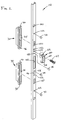
- a latch system mounts to an enclosure door 12, as shown in Figure 8.
- the latch system 10 mounts to the interior of the door 12 and extends through the door only at orifices 92, as explained hereinafter, positioned outside of a gasket 90.
- the gasket 90 engages an enclosure frame 11 and provides for a sealed enclosure.
- the latch system 10 includes a latch bar 14 mountable to the inside of the door 12.
- the latch bar 14 includes a rack and pinion assembly 18 with one or more rack members 30 extending through the orifice 92, as shown in Figure 3, to engage an actuator 16 on the exterior of the door 12, as also shown in Figure 9.
- the actuator 16 can take on a number of configurations which provide for actuating the latch system 10.
- the actuator 16 may be configured for rotation by a tool or connection to a handle, depending on the needs of the enclosure and its environment.
- the actuator 16 includes a tool receiving portion 56 and teeth 54 configured for intermeshing with the rack members 30, as explained hereinafter.
- the actuator 16 also includes a stop portion 58 to limit rotation of the actuator 16.
- the latch system 10 is adaptable for receiving a lock or other actuator mountable on the exterior of the door 12. It can be appreciated that the actuator 16 is mounted entirely on the exterior of the door 12, while the latching system 10 is mounted on the interior of the door. Only the rack members 30 extend through the orifices 92 to engage the actuator 16. With this configuration, sealing is much easier than systems requiring a number of components mounted through the door 12 inside of the gasketed region of the enclosure.
- the latch bar includes a number of finger members 20 which engage latch catches 22 which mount to the enclosure frame 11, as shown in Figure 3.
- the latch bar 14 also includes glides 24 mounted thereon which slide against the door surface and mounting clips 26 which retain the latch bar 14 substantially against the door 12.
- the latch system 10 mounts on the interior of the door 12 with the rack members 30 extending through the orifice 92 to engage the actuator 16, which mounts entirely on the exterior of the door 12.
- the other elements of the latch system 10 attached to the latch bar 14 are all on the interior of the door 12.
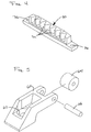
- the rack members 30 includes a number of teeth 32 aligned along an elongate portion, as shown in Figure 4 and engaging the actuator 16, as shown in Figure 9.
- the rack member 30 also includes a tab 34 extending in an opposite direction from the teeth 32 which inserts through an elongate slot 40 formed through the latch bar 14, as shown most clearly in Figure 2.
- the latch bar 14 is a substantially U-shaped channel member with slots and orifices formed through the bottom portion of the channel for receiving various latch system elements, as explained hereinafter.
- the ends of the rack member 30 include mounting bores 36 which receive screws 38 which mount to holes 42 formed in the base of the channel of the latch bar 14. It can be appreciated that the tab 34 extending through the slot 40 aligns the rack member 30. It can also be appreciated that the rack members 30 may be reversibly mounted in the channel of the latch bar 14 so that the actuator 16 may be used with different door configurations and mounted to engage the rack members 30 on either side of the orifice 92 formed through the door 12 and also provides for reversing the door 12 for opening to either the left or the right.
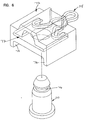
- the finger member 20 which extends upward from the latch bar 14 opposite the direction of the channel.
- the finger member 20 includes an extended raised finger portion 60 and a mounting orifice 62 which receives a screw or other mounting hardware 67 for attaching the finger member 20 to the latch bar 14.
- the finger member 20 includes a roller 64 mounted on a pin 66 at the extended end of the finger portion 60.
- the roller 64 is preferably a low friction material for easier engagement with the latch catch, as explained hereinafter.
- the finger member 20 also includes a center mounting post which inserts through the center hole 46, while the screws 67 insert into the holes 48 shown in Figure 1.
- the finger member 20 may be positioned to extend in either direction and then the mounting screw may be attached to the latch bar 14. This provides for easy reversibility of the finger members 20, which provides for reversibility of the door 12.
- the glides 24 mount into and extend from the channel portion of the latch bar 14 and are typically low friction plastic members which mount through orifices 50 in the latch bar 14 with screws 52 or other mounting hardware.
- the glide members 24 extend slightly beyond the channel portion of the latch bar 14 so that as the latch bar is slid back and forth, the glide members 24 engage the door surface to provide for reduced friction and easier movement of the latch system 10.
- the mounting clip 26 includes a stud portion 70 typically mounting to the interior surface of the door 12, as shown in Figure 3.
- the stud 70 includes a groove 76 formed therein and a tapered end portion which provides for easy insertion into the clip housing 72, as explained hereinafter.
- a cotter type pin 74 extends through a slot 77 in the housing and engages the groove in the stud 76.
- the pin 74 is removably mounted and provides for easily disengaging the housing 72 from the stud 70.
- the mounting clip 26 extends through a slot 44 formed in the latch bar 14.
- the stud 70 extends through the slot, while the housing 72 engages the exterior of the base of the latch bar 14 with side portions 78 aligning and retaining the latch bar. In this manner, the latch bar 14 is retained against the door 12.
- the housing 72 is also formed with plastic to reduce friction, while the latch bar slides 14 against the housing. It can be appreciated that the stud portion 70 slides within the slot 44 to limit the motion of the latch bar 14. In this manner, rotation of the actuator 16 to move the racks 30 back and forth is limited by the length of the slot 44, as the slots 44 engage the studs 70.
- the latch catch 22 includes a base 80 which may be configured for receiving a gasket 88 for sealing against the enclosure 11, as shown in Figure 3.
- a riser portion 82 extends upward to support oppositely positioned retainer members 84.
- the retainer members 84 each include an upward angled portion 86 extending outward longitudinally from each end of the latch catch 22.
- the latch catch 22 is mounted so that when the door is closed, the rollers 64 of the finger members 20 engage the angled portion 86 of the latch catch 22.
- the angled portion 86 acts as a ramp to guide the finger members 20 into engagement with the latch catch 22 so that the finger portion 60 properly engages the retainer member 84 of the catch 22.
- the latch catch 22 and the finger member 20 provide tight closure and some pressure against the gasket for a tight, sealed environment on the interior of the enclosure. It can be appreciated that with the configuration of the latch catch 22, the retainer members 84 are positioned on either end of the latch. This configuration provides for engagement from either end of the latch catch 22 by a corresponding finger member 20. The operating direction of the door 12 is reversible so that the latch catch 22 may be used with doors opening to either the left or the right without requiring two differently configured parts.
- the latch system 10 provides for great flexibility in mounting, and especially for mounting with a sealed enclosure.
- the latch system 10 mounts substantially on a latch bar 14 which requires extension through the door 12 only for the rack members 30.
- the door 12 is modified only by forming orifices 92 therethrough for accepting the latch system 10.
- the latch bar mounts on mounting studs 70 which are typically welded to the interior of the door 12.
- the present invention provides for a latch system 10 which is mounted exterior of the sealing gaskets 90 of the door 12. In this manner, greater flexibility and ease of use is provided, while still maintaining a dust-free and water-tight sealed enclosure.
- the latch system 10 can be reversed at any time for changing the direction of the door 12 from opening to either the left or the right.
- the latch system 10 includes reversible rack members 30 and reversible finger members 20 which engage latch catches 22 which are configured for accepting engagement of the finger member 20 at either end.
- the actuator 16 is mounted entirely exterior of the door 12 so that the actuator 16 may also be reversed to engage either of the rack members 30.
- the latch system 10 also engages the actuator 16 which may be configured for moving the latch system with rotation in either a clockwise or counterclockwise direction, depending upon the needs of the enclosure, as the stop portion 58 may be repositioned to limit rotation as needed.
- the latch system 10 also requires little modification should there be locking requirements, as hardware is mountable exterior of the door 12 with the actuator 16.
Landscapes
- Engineering & Computer Science (AREA)
- Mechanical Engineering (AREA)
- Specific Sealing Or Ventilating Devices For Doors And Windows (AREA)
- Lock And Its Accessories (AREA)
- Casings For Electric Apparatus (AREA)
Applications Claiming Priority (2)
| Application Number | Priority Date | Filing Date | Title |
|---|---|---|---|
| US609356 | 1996-03-01 | ||
| US08/609,356 US5642909A (en) | 1996-03-01 | 1996-03-01 | Latch system |
Publications (3)
| Publication Number | Publication Date |
|---|---|
| EP0792986A2 true EP0792986A2 (de) | 1997-09-03 |
| EP0792986A3 EP0792986A3 (de) | 2000-04-26 |
| EP0792986B1 EP0792986B1 (de) | 2006-12-13 |
Family
ID=24440451
Family Applications (1)
| Application Number | Title | Priority Date | Filing Date |
|---|---|---|---|
| EP97102950A Expired - Lifetime EP0792986B1 (de) | 1996-03-01 | 1997-02-22 | Behältnis mit einer Tür und einem Verschlussystem |
Country Status (9)
| Country | Link |
|---|---|
| US (1) | US5642909A (de) |
| EP (1) | EP0792986B1 (de) |
| JP (1) | JP3996665B2 (de) |
| KR (1) | KR970065941A (de) |
| CA (1) | CA2197845C (de) |
| CZ (1) | CZ61497A3 (de) |
| DE (1) | DE69737076T2 (de) |
| PL (1) | PL182514B1 (de) |
| SG (1) | SG49358A1 (de) |
Families Citing this family (42)
| Publication number | Priority date | Publication date | Assignee | Title |
|---|---|---|---|---|
| US6139070A (en) * | 1997-04-10 | 2000-10-31 | Truth Hardware Corporation | Integrated power window lock |
| US5906403A (en) * | 1997-05-12 | 1999-05-25 | Truth Hardware Corporation | Multipoint lock for sliding patio door |
| DE19742511C2 (de) * | 1997-09-26 | 2002-07-25 | Rittal Gmbh & Co Kg | Schubstangenverschluß für eine an einem Schaltschrank-Korpus angelenkte Schranktüre |
| FR2772821B1 (fr) * | 1997-12-22 | 2000-02-18 | Ferco Int Usine Ferrures | Cremone-serrure pour porte, porte-fenetre ou analogue |
| US6068308A (en) | 1998-03-13 | 2000-05-30 | Austin Hardware, Inc. | Latch assembly |
| US6065314A (en) * | 1998-05-22 | 2000-05-23 | Nicholson; John W. | Lock for freight containers |
| US6502872B1 (en) | 1998-10-09 | 2003-01-07 | Austin Hardware, Inc. | Latch assembly |
| US6161881A (en) * | 1999-06-30 | 2000-12-19 | Andersen Corporation | Casement lock |
| US6354119B1 (en) | 1999-11-24 | 2002-03-12 | Austin Hardware, Inc. | Handle and lock |
| US6532778B2 (en) | 2000-10-23 | 2003-03-18 | Allegis Corporation | Double lock T-handle assembly |
| US6952940B2 (en) | 2000-10-23 | 2005-10-11 | Allegis Corporation | Double lock T-handle assembly |
| DE50014457D1 (de) * | 2000-12-01 | 2007-08-16 | Emz Hanauer Gmbh & Co Kgaa | Türverriegelung |
| US6637784B1 (en) * | 2001-09-27 | 2003-10-28 | Builders Hardware Inc. | One-touch-actuated multipoint latch system for doors and windows |
| US7178839B2 (en) * | 2003-06-09 | 2007-02-20 | Imperial Usa, Ltd. | Latch assembly for sliding doors |
| US20040256860A1 (en) * | 2003-06-17 | 2004-12-23 | Tsai Miao Hsueh | Latch assembly for sliding doors |
| US6983962B2 (en) * | 2003-12-10 | 2006-01-10 | Inovec Pty Ltd. | Deadlock arrangement for locks |
| US20060006677A1 (en) * | 2004-07-09 | 2006-01-12 | Washington Matthew P | Locker latch assembly |
| DE102004036612A1 (de) * | 2004-07-28 | 2006-03-23 | Krauss-Maffei Wegmann Gmbh & Co. Kg | Verriegelungsvorrichtung an Lukendeckeln oder Verschlussklappen von Fahrzeugen, insbesondere Kampffahrzeugen |
| US7604265B2 (en) * | 2004-11-04 | 2009-10-20 | Imperial Usa, Ltd. | Latch assembly for sliding doors |
| US7293666B2 (en) * | 2004-11-17 | 2007-11-13 | American Power Conversion Corporation | Equipment enclosure kit and assembly method |
| CA2545852A1 (en) * | 2005-05-02 | 2006-11-02 | Truth Hardware Corporation | Multi-point sash lock system for casement window |
| US8226130B2 (en) | 2005-12-09 | 2012-07-24 | Industrilås i NässjöAB | Control roller mechanism-activator |
| US7761958B2 (en) * | 2005-12-09 | 2010-07-27 | Allegris Corporation | Hinge and latch mechanism |
| US7726750B2 (en) * | 2006-06-30 | 2010-06-01 | Hoffman Enclosures, Inc. | Latch for enclosure |
| CA2631923C (en) * | 2007-05-21 | 2015-07-07 | Truth Hardware Corporation | Multipoint lock mechanism |
| BR122019019969B1 (pt) | 2007-09-28 | 2020-11-17 | Wabtec Holding Corp | mecanismo de travamento auxiliar para uso com um mecanismo de operação de porta lançadeira elétrica |
| US8714667B2 (en) | 2007-10-01 | 2014-05-06 | Hoffman Enclosures, Inc. | Configurable enclosure for electronics components |
| US7819443B2 (en) * | 2007-11-19 | 2010-10-26 | Ventfabrics, Inc. | Door latch assembly |
| CA2681067C (en) * | 2008-10-03 | 2015-04-14 | Truth Hardware Corporation | Sliding door multipoint mortise lock with shoot bolts |
| CA2708912C (en) | 2009-06-30 | 2013-02-19 | Truth Hardware Corporation | Multi-point mortise lock mechanism for swinging door |
| CA2756363C (en) | 2010-10-27 | 2018-09-04 | Truth Hardware Corporation | Self locating tie bar guide for sash lock tie bars |
| EP2532813B1 (de) * | 2011-06-08 | 2014-09-10 | Roto Frank Ag | Zahnstange |
| CA2839501A1 (en) | 2013-01-17 | 2014-07-17 | Truth Hardware Corporation | Low profile high performance casement and awning window keeper |
| US9175506B2 (en) | 2013-03-15 | 2015-11-03 | Truth Hardware Corporation | Adjustable lock point for lock tie bars |
| EP3120430B1 (de) * | 2014-03-21 | 2018-04-11 | ABB Schweiz AG | Verriegelungsvorrichtung für einen schaltschrank |
| CA2895036C (en) | 2014-06-20 | 2022-09-20 | Truth Hardware Corporation | Recessed lock actuating device for sliding doors |
| US11220845B2 (en) * | 2015-06-08 | 2022-01-11 | Andersen Corporation | Powered sash lock and control systems therefor |
| WO2017079327A1 (en) * | 2015-11-02 | 2017-05-11 | Hoffman Enclosures, Inc. | Latching arrangement |
| WO2018048442A1 (en) * | 2016-09-12 | 2018-03-15 | Hewlett-Packard Development Company, L.P. | Releasable latch |
| DE102017114094A1 (de) * | 2017-03-27 | 2018-09-27 | Rittal Gmbh & Co. Kg | Schubstangenverschluss für ein Schaltschrankgehäuse sowie eine entsprechende Anordnung und ein entsprechendes Verfahren |
| EP3696354B1 (de) * | 2019-02-18 | 2022-06-15 | Industrilås i Nässjö Aktiebolag | Neu arrangierbare verriegelungsanordnung für eine tür |
| CA3093608A1 (en) | 2019-09-17 | 2021-03-17 | Truth Hardware Corporation | Tie bar and guide for casement window |
Citations (7)
| Publication number | Priority date | Publication date | Assignee | Title |
|---|---|---|---|---|
| FR2268933A1 (de) * | 1974-04-26 | 1975-11-21 | Herpen Frederik Van | |
| GB2072740A (en) * | 1980-03-22 | 1981-10-07 | Gkn Crompton | Espagnolette fastening |
| GB2142372A (en) * | 1983-05-24 | 1985-01-16 | Securistyle Ltd | Improvements in or relating to window fasteners |
| CA1270152A (en) * | 1985-02-06 | 1990-06-12 | Palladium Products Inc. | Window security bar system |
| DE9305893U1 (de) * | 1993-04-20 | 1993-06-17 | Knuerr-Mechanik Fuer Die Elektronik Ag, 8000 Muenchen, De | |
| US5407263A (en) * | 1991-11-27 | 1995-04-18 | Federal-Hoffman, Inc. | Restructurable enclosure with multi-purpose mounting blocks |
| US5481889A (en) * | 1993-01-15 | 1996-01-09 | Federal-Hoffman, Inc. | Mechanical latch system |
Family Cites Families (8)
| Publication number | Priority date | Publication date | Assignee | Title |
|---|---|---|---|---|
| DE286041C (de) * | ||||
| AT81685B (de) * | 1912-08-06 | 1920-11-10 | Richard Greenhalgh Greenhalgh | Verschlußvorrichtung, insbesondere für EisenbahnwaVerschlußvorrichtung, insbesondere für Eisenbahnwagentüren. gentüren. |
| FR809075A (fr) * | 1935-11-14 | 1937-02-23 | Porte étanche pour abris collectifs et autres applications | |
| GB2148377B (en) * | 1983-10-22 | 1987-02-18 | Hardware & Systems Patents Ltd | Improvements in fasteners for doors, windows and the like |
| EP0261268B1 (de) * | 1986-09-25 | 1990-06-20 | Dieter Ramsauer | Stangenverschluss mit von der Stange getragenen Verriegelungszapfen, insbesondere Doppelrollzapfen |
| DE3710563A1 (de) * | 1987-03-30 | 1988-10-20 | Loh Kg Rittal Werk | Schaltschrank mit schrankkorpus und daran angelenkter schranktuer |
| JPH0173277U (de) * | 1987-11-04 | 1989-05-17 | ||
| US5172944A (en) * | 1991-11-27 | 1992-12-22 | Federal-Hoffman, Inc. | Multiple point cam-pinion door latch |
-
1996
- 1996-03-01 US US08/609,356 patent/US5642909A/en not_active Expired - Lifetime
-
1997
- 1997-02-18 CA CA002197845A patent/CA2197845C/en not_active Expired - Fee Related
- 1997-02-21 SG SG1997000452A patent/SG49358A1/en unknown
- 1997-02-22 EP EP97102950A patent/EP0792986B1/de not_active Expired - Lifetime
- 1997-02-22 DE DE69737076T patent/DE69737076T2/de not_active Expired - Fee Related
- 1997-02-25 PL PL97318641A patent/PL182514B1/pl not_active IP Right Cessation
- 1997-02-26 KR KR1019970006060A patent/KR970065941A/ko not_active Application Discontinuation
- 1997-02-27 CZ CZ97614A patent/CZ61497A3/cs unknown
- 1997-02-28 JP JP06254497A patent/JP3996665B2/ja not_active Expired - Fee Related
Patent Citations (7)
| Publication number | Priority date | Publication date | Assignee | Title |
|---|---|---|---|---|
| FR2268933A1 (de) * | 1974-04-26 | 1975-11-21 | Herpen Frederik Van | |
| GB2072740A (en) * | 1980-03-22 | 1981-10-07 | Gkn Crompton | Espagnolette fastening |
| GB2142372A (en) * | 1983-05-24 | 1985-01-16 | Securistyle Ltd | Improvements in or relating to window fasteners |
| CA1270152A (en) * | 1985-02-06 | 1990-06-12 | Palladium Products Inc. | Window security bar system |
| US5407263A (en) * | 1991-11-27 | 1995-04-18 | Federal-Hoffman, Inc. | Restructurable enclosure with multi-purpose mounting blocks |
| US5481889A (en) * | 1993-01-15 | 1996-01-09 | Federal-Hoffman, Inc. | Mechanical latch system |
| DE9305893U1 (de) * | 1993-04-20 | 1993-06-17 | Knuerr-Mechanik Fuer Die Elektronik Ag, 8000 Muenchen, De |
Also Published As
| Publication number | Publication date |
|---|---|
| EP0792986A3 (de) | 2000-04-26 |
| CZ61497A3 (en) | 1997-10-15 |
| DE69737076T2 (de) | 2007-06-14 |
| PL318641A1 (en) | 1997-09-15 |
| SG49358A1 (en) | 1998-05-18 |
| JP3996665B2 (ja) | 2007-10-24 |
| PL182514B1 (pl) | 2002-01-31 |
| EP0792986B1 (de) | 2006-12-13 |
| DE69737076D1 (de) | 2007-01-25 |
| CA2197845A1 (en) | 1997-09-01 |
| CA2197845C (en) | 2007-05-08 |
| US5642909A (en) | 1997-07-01 |
| JPH09328945A (ja) | 1997-12-22 |
| KR970065941A (ko) | 1997-10-13 |
Similar Documents
| Publication | Publication Date | Title |
|---|---|---|
| US5642909A (en) | Latch system | |
| EP1070187B1 (de) | Rollstabsystem für einen mehrpunktriegel | |
| EP0501803A1 (de) | Treibstangenverschlussmechanismus | |
| US6174007B1 (en) | Actuator assembly | |
| US4307904A (en) | Lock mechanism | |
| US5437485A (en) | Locking mechanism for windows or doors | |
| US7708322B2 (en) | Actuator for use in fenestration systems | |
| EP0276757B1 (de) | Mit einer Torsionsfeder angetriebene Tür | |
| EP0510280B1 (de) | Vorrichtung zum Verriegeln von Tür- oder Fensterflügeln | |
| GB2423792A (en) | Espagnolette locking mechanism | |
| EP0742332A1 (de) | Treibstangenverschlussbefestigungsanordnung | |
| US3878585A (en) | Hinge assembly | |
| US4569213A (en) | Compartment closure assembly with latching apparatus having combination lock | |
| US6068304A (en) | Espagnolette edge bar assembly | |
| GB2303166A (en) | Operating system for a multi-point lock | |
| KR200386690Y1 (ko) | 창호 잠금장치의 지지구조물 | |
| GB2323122A (en) | Double shoot bolt fastening | |
| EP1910635B1 (de) | Sicherheitsrahmen für türen und fenster | |
| EP1155206B1 (de) | Zusatzverriegelung für aktenkoffer, tragbare rechner oder dergleichen | |
| GB2498926A (en) | Restrictor assembly for a friction stay hinge | |
| EP1479862A2 (de) | Betätigungsvorrichtung für Türen und Fenster | |
| US20230265695A1 (en) | Hinge lock | |
| GB2261697A (en) | Locking system | |
| GB2293860A (en) | Shoot bolt fastening for windows or doors | |
| GB2382617A (en) | Shoot bolt assembly |
Legal Events
| Date | Code | Title | Description |
|---|---|---|---|
| PUAI | Public reference made under article 153(3) epc to a published international application that has entered the european phase |
Free format text: ORIGINAL CODE: 0009012 |
|
| AK | Designated contracting states |
Kind code of ref document: A2 Designated state(s): DE FR GB IT |
|
| PUAL | Search report despatched |
Free format text: ORIGINAL CODE: 0009013 |
|
| AK | Designated contracting states |
Kind code of ref document: A3 Designated state(s): DE FR GB IT |
|
| RAP1 | Party data changed (applicant data changed or rights of an application transferred) |
Owner name: HOFFMAN ENCLOSURES INC. |
|
| 17P | Request for examination filed |
Effective date: 20001013 |
|
| 17Q | First examination report despatched |
Effective date: 20030806 |
|
| GRAP | Despatch of communication of intention to grant a patent |
Free format text: ORIGINAL CODE: EPIDOSNIGR1 |
|
| RTI1 | Title (correction) |
Free format text: ENCLOSURE HAVING A DOOR AND A LATCH SYSTEM |
|
| GRAS | Grant fee paid |
Free format text: ORIGINAL CODE: EPIDOSNIGR3 |
|
| GRAA | (expected) grant |
Free format text: ORIGINAL CODE: 0009210 |
|
| AK | Designated contracting states |
Kind code of ref document: B1 Designated state(s): DE FR GB IT |
|
| REG | Reference to a national code |
Ref country code: GB Ref legal event code: FG4D |
|
| REF | Corresponds to: |
Ref document number: 69737076 Country of ref document: DE Date of ref document: 20070125 Kind code of ref document: P |
|
| PGFP | Annual fee paid to national office [announced via postgrant information from national office to epo] |
Ref country code: GB Payment date: 20070223 Year of fee payment: 11 |
|
| PGFP | Annual fee paid to national office [announced via postgrant information from national office to epo] |
Ref country code: DE Payment date: 20070330 Year of fee payment: 11 |
|
| ET | Fr: translation filed | ||
| PLBE | No opposition filed within time limit |
Free format text: ORIGINAL CODE: 0009261 |
|
| STAA | Information on the status of an ep patent application or granted ep patent |
Free format text: STATUS: NO OPPOSITION FILED WITHIN TIME LIMIT |
|
| 26N | No opposition filed |
Effective date: 20070914 |
|
| PGFP | Annual fee paid to national office [announced via postgrant information from national office to epo] |
Ref country code: IT Payment date: 20070608 Year of fee payment: 11 |
|
| PGFP | Annual fee paid to national office [announced via postgrant information from national office to epo] |
Ref country code: FR Payment date: 20070221 Year of fee payment: 11 |
|
| GBPC | Gb: european patent ceased through non-payment of renewal fee |
Effective date: 20080222 |
|
| REG | Reference to a national code |
Ref country code: FR Ref legal event code: ST Effective date: 20081031 |
|
| PG25 | Lapsed in a contracting state [announced via postgrant information from national office to epo] |
Ref country code: DE Free format text: LAPSE BECAUSE OF NON-PAYMENT OF DUE FEES Effective date: 20080902 |
|
| PG25 | Lapsed in a contracting state [announced via postgrant information from national office to epo] |
Ref country code: FR Free format text: LAPSE BECAUSE OF NON-PAYMENT OF DUE FEES Effective date: 20080229 |
|
| PG25 | Lapsed in a contracting state [announced via postgrant information from national office to epo] |
Ref country code: GB Free format text: LAPSE BECAUSE OF NON-PAYMENT OF DUE FEES Effective date: 20080222 |
|
| PG25 | Lapsed in a contracting state [announced via postgrant information from national office to epo] |
Ref country code: IT Free format text: LAPSE BECAUSE OF NON-PAYMENT OF DUE FEES Effective date: 20080222 |