EP0792820B1 - Flaschenspender zur gleichzeitigen Abgabe von zwei Produkten - Google Patents
Flaschenspender zur gleichzeitigen Abgabe von zwei Produkten Download PDFInfo
- Publication number
- EP0792820B1 EP0792820B1 EP97101566A EP97101566A EP0792820B1 EP 0792820 B1 EP0792820 B1 EP 0792820B1 EP 97101566 A EP97101566 A EP 97101566A EP 97101566 A EP97101566 A EP 97101566A EP 0792820 B1 EP0792820 B1 EP 0792820B1
- Authority
- EP
- European Patent Office
- Prior art keywords
- flexible vessels
- pressing
- discharge
- vessels
- roller
- Prior art date
- Legal status (The legal status is an assumption and is not a legal conclusion. Google has not performed a legal analysis and makes no representation as to the accuracy of the status listed.)
- Expired - Lifetime
Links
Images


Classifications
-
- B—PERFORMING OPERATIONS; TRANSPORTING
- B65—CONVEYING; PACKING; STORING; HANDLING THIN OR FILAMENTARY MATERIAL
- B65D—CONTAINERS FOR STORAGE OR TRANSPORT OF ARTICLES OR MATERIALS, e.g. BAGS, BARRELS, BOTTLES, BOXES, CANS, CARTONS, CRATES, DRUMS, JARS, TANKS, HOPPERS, FORWARDING CONTAINERS; ACCESSORIES, CLOSURES, OR FITTINGS THEREFOR; PACKAGING ELEMENTS; PACKAGES
- B65D35/00—Pliable tubular containers adapted to be permanently or temporarily deformed to expel contents, e.g. collapsible tubes for toothpaste or other plastic or semi-liquid material; Holders therefor
- B65D35/24—Pliable tubular containers adapted to be permanently or temporarily deformed to expel contents, e.g. collapsible tubes for toothpaste or other plastic or semi-liquid material; Holders therefor with auxiliary devices
- B65D35/28—Pliable tubular containers adapted to be permanently or temporarily deformed to expel contents, e.g. collapsible tubes for toothpaste or other plastic or semi-liquid material; Holders therefor with auxiliary devices for expelling contents
- B65D35/285—Co-operating squeezing supporting rollers
-
- A—HUMAN NECESSITIES
- A45—HAND OR TRAVELLING ARTICLES
- A45D—HAIRDRESSING OR SHAVING EQUIPMENT; EQUIPMENT FOR COSMETICS OR COSMETIC TREATMENTS, e.g. FOR MANICURING OR PEDICURING
- A45D19/00—Devices for washing the hair or the scalp; Similar devices for colouring the hair
- A45D19/02—Hand-actuated implements, e.g. hand-actuated spray heads
- A45D19/026—Hand-actuated implements, e.g. hand-actuated spray heads having brush or comb applicators
-
- A—HUMAN NECESSITIES
- A45—HAND OR TRAVELLING ARTICLES
- A45D—HAIRDRESSING OR SHAVING EQUIPMENT; EQUIPMENT FOR COSMETICS OR COSMETIC TREATMENTS, e.g. FOR MANICURING OR PEDICURING
- A45D34/00—Containers or accessories specially adapted for handling liquid toiletry or cosmetic substances, e.g. perfumes
- A45D34/04—Appliances specially adapted for applying liquid, e.g. using roller or ball
- A45D34/041—Appliances specially adapted for applying liquid, e.g. using roller or ball using a roller, a disc or a ball
-
- B—PERFORMING OPERATIONS; TRANSPORTING
- B65—CONVEYING; PACKING; STORING; HANDLING THIN OR FILAMENTARY MATERIAL
- B65D—CONTAINERS FOR STORAGE OR TRANSPORT OF ARTICLES OR MATERIALS, e.g. BAGS, BARRELS, BOTTLES, BOXES, CANS, CARTONS, CRATES, DRUMS, JARS, TANKS, HOPPERS, FORWARDING CONTAINERS; ACCESSORIES, CLOSURES, OR FITTINGS THEREFOR; PACKAGING ELEMENTS; PACKAGES
- B65D81/00—Containers, packaging elements, or packages, for contents presenting particular transport or storage problems, or adapted to be used for non-packaging purposes after removal of contents
- B65D81/32—Containers, packaging elements, or packages, for contents presenting particular transport or storage problems, or adapted to be used for non-packaging purposes after removal of contents for packaging two or more different materials which must be maintained separate prior to use in admixture
- B65D81/3233—Flexible containers disposed within rigid containers
- B65D81/3244—Flexible containers disposed within rigid containers arranged parallel or concentrically and permitting simultaneous dispensing of the two materials without prior mixing
-
- B—PERFORMING OPERATIONS; TRANSPORTING
- B65—CONVEYING; PACKING; STORING; HANDLING THIN OR FILAMENTARY MATERIAL
- B65D—CONTAINERS FOR STORAGE OR TRANSPORT OF ARTICLES OR MATERIALS, e.g. BAGS, BARRELS, BOTTLES, BOXES, CANS, CARTONS, CRATES, DRUMS, JARS, TANKS, HOPPERS, FORWARDING CONTAINERS; ACCESSORIES, CLOSURES, OR FITTINGS THEREFOR; PACKAGING ELEMENTS; PACKAGES
- B65D83/00—Containers or packages with special means for dispensing contents
- B65D83/76—Containers or packages with special means for dispensing contents for dispensing fluent contents by means of a piston
- B65D83/761—Containers or packages with special means for dispensing contents for dispensing fluent contents by means of a piston the piston being actuated by a screw-shaft
-
- A—HUMAN NECESSITIES
- A45—HAND OR TRAVELLING ARTICLES
- A45D—HAIRDRESSING OR SHAVING EQUIPMENT; EQUIPMENT FOR COSMETICS OR COSMETIC TREATMENTS, e.g. FOR MANICURING OR PEDICURING
- A45D2200/00—Details not otherwise provided for in A45D
- A45D2200/05—Details of containers
- A45D2200/058—Means for mixing different substances prior to application
Definitions
- the present invention relates to a non-aerosol type discharge bottle from which two cream or gel agents contained in flexible vessels respectively can be discharged simultaneously of the type as disclosed in FR-A-265 14 85.
- Said conventional discharge bottle comprises pressing means for pressing liquid matters out of flexible vessels wherein said pressing means include roller-like pressing members disposed below the aforementioned flexible vessels, said flexible vessels being nipped between and pressed by said roller-like pressing members.
- a two-agent type cosmetic there is known a two-agent type hair dye composed of a first agent, for example, containing oxidation dyes, and a second agent, for example, containing an oxidizer such as hydrogen peroxide, or the like.
- a two-agent type hair bleach composed of a first agent containing an alkaline compound, and a second agent containing hydrogen peroxide.
- hair cosmetics such as hair dye, a hair bleach, etc.
- a two-agent type dentifrice composed of a first agent such as calcium carbonate, or the like, for providing a brushing/cleaning effect, and a second agent containing hydrogen peroxide for providing a bleaching effect.
- the first and second agents are contained in flexible vessels such as plastic tubes, tubes of lamination of metal foil and plastic sheet, etc., individually in view of safety of storage, and the cosmetic can be used after the first and second agents are discharged from the respective vessels and mixed with each other.
- Non-aerosol type discharge bottle having pressing means for pressing flexible vessels to discharge the liquid matters contained therein.
- Said pressing means include a screw-like shaft member and a disk-like pressing member threadedly engaged with said screw-like shaft member.
- the discharge bottle according to the present invention is designed so that a plurality of flexible vessels respectively containing cream or gel matters different from each other are arranged side by side by a holding vessel and the contents of the flexible vessels are discharged simultaneously by pressing the flexible vessels.
- various embodiments may be used so long as the contents of the plurality of flexible vessels can be discharged from the flexible vessels simultaneously.
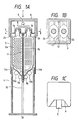
- Figs. 1A to 1C schematically show a discharge bottle according to a first embodiment of the present invention as one of embodiments in which the flexible vessels are pressed to discharge the contents of the flexible vessels in a manner as described above.
- the discharge bottle 1a comprises, in its side, two tube-like (cylindrical) or pouch-like (in the form of a flat bag obtained by sticking one or two sheets) flexible vessels 2a and 2b, a holding vessel 3 for arranging side by side the flexible vessels 2a and 2b vertically to put the mouth portions 2x and 2y of the flexible vessels 2a and 2b upside, a bottom vessel 4 located under the holding vessel 3 for supporting the holding vessel 3 in an erected state, and a cover 6 provided with a discharge hole 5.
- fitting holes 7a and 7b are formed in the mouth portions 2x and 2y of the flexible vessels 2a and 2b respectively so as to be communicated, through a discharge passage 8, with the discharge hole 5 provided in the cover 6.
- a first pair of roller-like pressing members 9a and 9b and a second pair of roller-like pressing members 10a and 10b are provided in the inside of the bottom vessel 4.
- the first pair of roller-like pressing members 9a and 9b are designed to nip the flexible vessels 2a and 2b arranged side by side in the holding vessel 3 so as to press the flexible vessels intensively whereas the second pair of roller-like pressing members 10a and 10b are designed to press the flexible vessels 2a and 2b more loosely than the first pair of roller-like pressing members 9a and 9b.
- a partition plate 11 is disposed between the two flexible vessels 2a and 2b.
- a guide 12 is provided for guiding the partition plate 11 so that not only the partition plate 11 can be held vertically but also the two flexible vessels 2a and 2b can be moved vertically.
- the partition plate 11 used herein include, for example, a 1-3 mm thick plate of a resin such as polyvinyl chloride, polyethylene, polypropylene, etc., and a 1-3 mm thick plate of a metal such as aluminum, etc.
- Pressing sheets 13a and 13b are respectively disposed between the flexible vessel 2a and the roller-like pressing members 9a and 10a, and between the flexible vessel 2b and the roller-like pressing members 9b and 10b.
- the pressing sheets 13a and 13b for example, polyethylene sheets each having a thickness of from about 0.5 mm to about 3 mm can be used preferably.
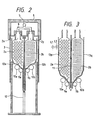
- the pressing sheets 13a and 13b are not limited to sheets of uniform thickness and drainboard-like sheets 13p and 13q may be provided as shown in Fig. 3. In this case, it is preferable to prepare the drainboard-like sheets 13p and 13q in such a manner as follows in order to smoothen the work of pressing the flexible vessels 2a and 2b as will be described later.
- the drainboard-like sheets are formed of board-like members each of which is made from resin such as polyethylene, or the like, and has a vertical length L1 (Fig. 3) in a range of from about 2 mm to about 20 mm and a thickness in a range of from about 1 mm to about 3 mm.
- the board-like members are arranged with intervals L2 in a range of about from 1 mm to 2 mm and adjacent ones of the board-like members are connected to each other through a sheet of resin such polyethylene, or the like, having a thickness in a range of from about 0.5 mm to about 2 mm.
- Examples of the flexible vessels arranged side by side in the inside of the holding vessel 3 include, for example, tube or pouch vessels each formed from a plastic sheet or a sheet of lamination of a metal thin film and a plastic sheet.
- contents of the flexible vessels various cream or gel matters may be used.
- such contents may be used as the first and second agents in a two-agent type hair dye, a two-agent type hair bleach, a two-agent type dentifrice, or the like.
- the cover 6 is pressed as indicated by the arrow after the flexible vessels 2a and 2b are contained in the holding vessel 3 and the mouth portions 2x and 2y of the flexible vessels 2a and 2b are fitted to the fitting holes 7a and 7b respectively. As a result, the cover 6 is pressed down as shown in Fig. 2 and, accordingly, the holding vessel 3 is also pressed down.
- the flexible vessels 2a and 2b are inserted into a gap between the first pair of roller-like pressing members 9a and 9b from the lower end portions of the flexible vessels 2a and 2b, so that the first pair of roller-like pressing members 9a and 9b slide relatively toward the mouth portions 2x and 2y of the flexible vessels 2a and 2b. Accordingly, the flexible vessels 2a and 2b are squeezed gradually upward from the lower end portions thereof, so that the contents of the two flexible vessels 2a and 2b are discharged simultaneously through the discharge hole 5 of the cover 6 in accordance with the amount of pressing against the cover 6. Accordingly, in use of such a two-agent type cosmetic, conventional tiresomeness that two flexible vessels must be squeezed individually can be eliminated.
- the pressing operation can be carried out smoothly because the flexible vessels 2a and 2b are pressed loosely by the second pair of roller-like pressing members 10a and 10b in advance before the flexible vessels 2a and 2b are squeezed by intensive pressing by means of the first pair of roller-like pressing members 9a and 9b.
- the flexible vessels 2a and 2b are not pressed directly by the first pair of roller-like pressing members 9a and 9b but pressed through the pressing sheets 13a and 13b respectively. Accordingly, the pressing operation can be carried out more smoothly. Further, in the case of a pouch formed from a laminate sheet containing an aluminum layer, or the like, as a gas barrier layer, there is a risk that the gas barrier layer may be ruptured in the inside of the laminate sheet correspondingly to the pressing condition when the surface of the pouch is pressed by rollers. By using the pressing sheets 13a and 13b, however, the aforementioned rupture of the gas barrier layer can be prevented. Furthermore, by using drainboard-like sheets 13p and 13q shown in Fig.
- the pressing operation can be carried out more smoothly and more efficiently because the flexible vessels 2a and 2b can be pressed along the external shape of the drainboard-like sheets 13p and 13q so that the amounts of the contents remaining in the pressed regions of the flexible vessels 2a and 2b can be reduced greatly.
- stopper tensile rings 14 can be provided multistageously in the bottom vessel 4. Each of the stopper tensile rings 14 can be removed from the bottom vessel 4 by pulling as indicated by the arrow A.
- stopper projections 15 can be provided in the bottom vessel 4.
- Each of the stopper projections 15 is designed so that the projection 15 is projected from a side wall surface of the bottom vessel 4 or put into the side wall by sliding as indicated by the arrow.
- stopper pluck rings 16 can be provided in the bottom vessel 4.
- Each of the pluck rings 16 is designed so that the ring 16 per se can be plucked from the bottom vessel 4 by turning its knob 16a.
- a check-valve can be further provided in the discharge passage 8 between the fitting holes 7a and 7b and the discharge hole 5, if necessary.
- check-valve 20 various known valves may be used.
- the check-valve 20 is constituted by a small-diameter cylindrical member 21, a large-diameter cylindrical member 22, long and short beam-like members 23 formed alternately so as to project from the joint portion of these cylindrical members toward the axial center of the large-diameter cylindrical member 22, and an elastic valve 24 fitted to the small-diameter cylindrical member 21 side of the beam-like members 23.
- ends of the long beam-like members 23 are connected to a ring.
- the elastic valve 24 substantially has a shape as indicated by the solid line in Fig.
- the elastic valve 24 is, however, designed so as to be deformed as indicated by the broken line in Fig. 7C when pressed as indicated by the arrow in Fig. 7C while the elastic valve 24 is restored to its original shape when the pressing is released.
- the check-valve 20 is provided in the discharge passage 8 of the discharge bottle 1a in Fig. 1A so that the small-diameter cylindrical member 21 is located in the discharge hole 5 side of the discharge bottle 1a whereas the large-diameter cylindrical member 22 is located in the fitting hole 7a or 7b side
- the content of either of the flexible vessels 2a and 2b presses the elastic valve 24 and passes through the check-valve 20 as indicated by the arrow in Fig. 8 so as to be discharged through the discharge hole 5 when the flexible vessels 2a and 2b are squeezed from its lower end portions.
- the content discharged from either of the flexible vessels 2a and 2b is prevented from returning to the flexible vessel 2a or 2b. Accordingly, even after the flexible vessels 2a and 2b are attached into the discharge bottle 1a, the contents of the flexible vessels 2a and 2b can be preserved stably.
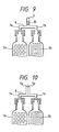
- Fig. 1A has shown the case where the contents discharged from the mouth portions 2x and 2y of the two flexible vessels 2a and 2b are brought into contact with each other in the discharge passage 8 of the discharge bottle 1a before reaching the discharge hole 5 of the discharge bottle 1a so that the contents are discharged in a slightly mixed state through the discharge hole 5, if necessary, the invention can be applied to the case where a mixing means 25 is provided in the discharge passage 8 as shown in Fig. 9 so that the contents of the two flexible vessels 2a and 2b are discharged in a sufficiently mixed state through the discharge hole 5.
- the mixing means for example, there can be used a means formed by providing helical plates having inclinations reverse to each other with respect to the center of the axis.
- the invention can be applied also to the case where the discharge bottle is contrariwise designed so that the contents of the two flexible vessels 2a and 2b are first mixed just before they are discharged through the discharge hole 5.
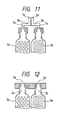
- the discharge passage 8 may be divided into two channels in its inside so that the contents are discharged through adjacent discharge holes 5a and 5b respectively.
- the discharge bottle may be designed so that the contents of the two flexible vessels 2a and 2b are discharged through discharge holes 5a and 5b of discharge passages 8a and 8b provided quite separately.
- the discharge holes 5a and 5b of the discharge bottle may be made to serve as fitting holes 7a and 7b for fitting the mouth portions 2x and 2y of the flexible vessels 2a and 2b so that the discharge passage 8 can be omitted.
- the aforementioned embodiment has been described about the case where, for example, the number of flexible vessels arranged side by side in the holding vessel is two so that the contents of the two flexible vessels are discharged simultaneously
- the invention can be applied also to the case where three or more flexible vessels are arranged side by side in the holding vessel, if necessary, so that the contents thereof are discharged simultaneously.
- one discharge hole may be provided in the discharge bottle or a plurality of discharge holes may be provided in the discharge bottle.
- a comb-like coater is preferably attached to the end portion of the discharge hole 5 in the discharge bottle.
- an opening portion is provided between the comb teeth so as to be communicated with the discharge hole 5, so that two agents in the two-agent type hair dye are discharged simultaneously through the opening portion.
- the hair dying operation can be carried out more simply by using such a coater attached to the discharge bottle according to the present invention.
- two agents in a two-agent type cosmetic such as a hair dye, or the like, can be discharged simultaneously in use, so that the convenience in use of the two-agent type cosmetic can be improved greatly.
Landscapes
- Engineering & Computer Science (AREA)
- Mechanical Engineering (AREA)
- Containers And Packaging Bodies Having A Special Means To Remove Contents (AREA)
- Tubes (AREA)
Claims (3)
- Aerosolfreie Spenderdose, die Folgendes umfasst:dadurch gekennzeichnet, dass die Druckeinrichtung ein erstes Paar walzenförmige Druckelemente (9a, 9b) zum intensiven Zusammendrücken der flexiblen Behälter (2a, 2b) und ein zweites Paar walzenförmige Druckelemente (10a, 10b) aufweist, das sich näher als das erste Paar walzenförmige Druckelemente an den Spendeöffnungsabschnitten (2x, 2y) der flexiblen Behälter befindet und dazu dient, die flexiblen Behälter weniger fest als das erste Paar walzenförmige Druckelemente zusammenzudrücken.eine Vielzahl flexibler Behälter (2a, 2b), die jeweils unterschiedliche flüssige Stoffe enthalten, die aus der Gruppe creme- und gelartiger Stoffe ausgewählt werden;einen Haltebehälter (3), in dem die Vielzahl von Behältern vertikal nebeneinander so angeordnet ist, dass sich die Spendeöffnungsabschnitte (2x, 2y) der flexiblen Behälter oben befinden;mindestens eine Spendeöffnung (5) zum Spenden der flüssigen Stoffe; undeine Druckeinrichtung zum Zusammendrücken der flexiblen Behälter, um die flüssigen Stoffe durch die Spendeöffnung aus den flexiblen Behältern auszugeben,
- Spenderdose nach Anspruch 1, wobei die flexiblen Behälter (2a, 2b) zwischen den walzenförmigen Druckelementen eingeklemmt sind und von diesen zusammengedrückt werden, so dass sich die walzenförmigen Druckelemente (9a, 9b; 10a, 10b) relativ in Richtung der Spendeöffnungsabschnitte (2x, 2y) bewegen, wenn der Haltebehälter nach unten in Richtung der walzenförmigen Druckelemente gedrückt wird.
- Spenderdose nach Anspruch 2, wobei jeder der flexiblen Behälter (2a, 2b) eine Folie (13a, 13b, 13p, 13q) aufweist, durch die die walzenförmigen Druckelemente (9a, 9b; 10a, 10b) Druck auf die flexiblen Behälter ausüben.
Applications Claiming Priority (3)
| Application Number | Priority Date | Filing Date | Title |
|---|---|---|---|
| JP3896696 | 1996-01-31 | ||
| JP08038966A JP3077135B2 (ja) | 1996-01-31 | 1996-01-31 | 吐出容器 |
| JP38966/96 | 1996-01-31 |
Publications (3)
| Publication Number | Publication Date |
|---|---|
| EP0792820A2 EP0792820A2 (de) | 1997-09-03 |
| EP0792820A3 EP0792820A3 (de) | 1997-12-03 |
| EP0792820B1 true EP0792820B1 (de) | 2002-05-02 |
Family
ID=12539911
Family Applications (1)
| Application Number | Title | Priority Date | Filing Date |
|---|---|---|---|
| EP97101566A Expired - Lifetime EP0792820B1 (de) | 1996-01-31 | 1997-01-31 | Flaschenspender zur gleichzeitigen Abgabe von zwei Produkten |
Country Status (4)
| Country | Link |
|---|---|
| US (1) | US5848730A (de) |
| EP (1) | EP0792820B1 (de) |
| JP (1) | JP3077135B2 (de) |
| DE (1) | DE69712248T2 (de) |
Families Citing this family (82)
| Publication number | Priority date | Publication date | Assignee | Title |
|---|---|---|---|---|
| US6783514B2 (en) * | 1997-01-31 | 2004-08-31 | United States Surgical Corporation | Fibrin sealant applicator |
| JPH11199454A (ja) * | 1998-01-08 | 1999-07-27 | Yamahatsu Sangyo Kk | 2液式酸化染毛剤及び2液式脱色剤 |
| ATA49899A (de) * | 1999-03-19 | 2002-06-15 | Immuno Ag | Verfahren und vorrichtung zum mischen von komponenten |
| US6250346B1 (en) * | 1999-05-28 | 2001-06-26 | James Anzai Castillo | Device for maintaining separate ingredients in liquid food products |
| JP4043666B2 (ja) * | 1999-09-27 | 2008-02-06 | 前田建設工業株式会社 | 混練用ノズル |
| US6648641B1 (en) * | 2000-11-22 | 2003-11-18 | The Procter & Gamble Company | Apparatus, method and product for treating teeth |
| US6454133B1 (en) * | 2001-05-03 | 2002-09-24 | Kenneth Oscar Lopez | Toothpaste butler |
| NL1018232C2 (nl) * | 2001-06-07 | 2002-12-10 | Intercon Holland B V | Samenstel van een frame en een verpakking. |
| FR2826641B1 (fr) | 2001-06-29 | 2003-09-05 | Oreal | Dispositif pour la distribution simultanee de deux produits conditionnes separement |
| DE10207763A1 (de) * | 2002-02-23 | 2003-09-04 | Fischer Artur Werke Gmbh | Mehrkomponenten-Kartusche |
| DE10315550A1 (de) * | 2003-04-05 | 2004-10-14 | Wella Ag | Applikator zum Aufbringen einer oxidativen Haarfarbe |
| US8153108B2 (en) | 2003-04-25 | 2012-04-10 | Kao Corporation | Hair cosmetic product |
| DE10321322A1 (de) * | 2003-05-13 | 2004-12-02 | Hilti Ag | System mit Auspressvorrichtung und Lagerbehälter |
| HRP20030802A2 (en) * | 2003-10-03 | 2005-04-30 | Vrus-Pervan Iris | Precise hair colouring implement to form frosted and streaky hair and the method for protecting uncoloured hair |
| ATE548127T1 (de) * | 2003-10-03 | 2012-03-15 | Kao Corp | Abführvorrichtung |
| DE102005021076A1 (de) * | 2005-05-06 | 2006-11-09 | Fischerwerke Artur Fischer Gmbh & Co. Kg | Mehrkomponenten-Kartusche mit Rückschlagventil |
| JP2007297108A (ja) * | 2006-05-01 | 2007-11-15 | Hoyu Co Ltd | チューブ容器セット |
| JP2008056348A (ja) * | 2006-08-04 | 2008-03-13 | Kao Corp | 塗布容器 |
| CN101522070A (zh) * | 2006-10-09 | 2009-09-02 | 宝洁公司 | 包括吸收基质的毛发处理剂施用体系 |
| DE602007013991D1 (de) * | 2006-10-09 | 2011-06-01 | Procter & Gamble | Haarsträhnungsapplikator und Verfahren |
| US20080083420A1 (en) * | 2006-10-09 | 2008-04-10 | The Procter & Gamble Company | Hair treatment application system |
| EP1911368A1 (de) * | 2006-10-09 | 2008-04-16 | The Procter and Gamble Company | Haarbehandlungsanwendungssystem mit einem absorbierenden Substrat |
| EP1958532A3 (de) * | 2006-10-09 | 2013-06-05 | The Procter and Gamble Company | Haarbehandlungsanwendungssystem |
| US8573232B2 (en) | 2006-10-09 | 2013-11-05 | The Procter & Gamble Company | Hair treatment application system comprising an absorbent substrate |
| WO2008044198A1 (en) * | 2006-10-09 | 2008-04-17 | The Procter & Gamble Company | Hair treatment application system |
| CN200988015Y (zh) * | 2006-10-30 | 2007-12-12 | 埃森·费尔索夫 | 喷雾器 |
| US7896567B2 (en) * | 2006-11-21 | 2011-03-01 | The Procter & Gamble Company | Dispensing toothbrush |
| JP4684212B2 (ja) * | 2006-11-24 | 2011-05-18 | 日本キム株式会社 | 収容物注出装置、及びそれに用いられる収容体押圧装置 |
| US8136700B2 (en) * | 2007-02-23 | 2012-03-20 | Sealed Air Corporation (Us) | Dual chambered fluid dispenser with mixing chamber |
| EP2332437B1 (de) * | 2007-03-13 | 2013-05-01 | The Procter and Gamble Company | Werkzeug zum Behandeln von Haarsträhnen |
| US20080267005A1 (en) * | 2007-04-24 | 2008-10-30 | Tyco Healthcare Group Lp | Applicator system and method of use |
| DK2087878T3 (da) * | 2007-04-27 | 2011-08-01 | Kao Corp | Fremgangsmåde til at farve eller blege håret |
| KR101523112B1 (ko) | 2007-04-27 | 2015-05-26 | 카오카부시키가이샤 | 2 제식 염모용 또는 탈색용 모발 화장품 |
| CN101677667B (zh) | 2007-06-15 | 2012-08-08 | 宝洁公司 | 将毛发处理组合物施用到发束上的装置 |
| EP2005854B1 (de) | 2007-06-15 | 2017-04-12 | Noxell Corporation | System zum Strähnen von Haaren |
| US8132574B2 (en) * | 2007-06-15 | 2012-03-13 | The Procter & Gamble Company | Hair treatment applicator for providing hair strand effects |
| WO2008157104A1 (en) | 2007-06-15 | 2008-12-24 | The Procter & Gamble Company | Applicator for applying a hair treatment composition to a bundle of hair strands |
| CN101677668B (zh) * | 2007-06-15 | 2013-06-19 | 宝洁公司 | 用于毛发处理组合物的施用装置 |
| US20100251488A1 (en) | 2007-10-24 | 2010-10-07 | Kao Corporation | Head hair dyeing method |
| US8152858B2 (en) * | 2007-10-24 | 2012-04-10 | Kao Corporation | Head hair dyeing method |
| EP2070833B1 (de) * | 2007-12-14 | 2011-02-23 | The Procter & Gamble Company | Behälter mit einer Vorrichtung zum Verhindern des Verstopfens der Abgabevorrichtung des Behälters |
| EP2198738B1 (de) * | 2008-12-10 | 2018-09-05 | Noxell Corporation | Haarbehandlungsapplikator für verbesserte Haarsträhneneffekte |
| EP2196104B1 (de) * | 2008-12-10 | 2018-10-17 | Noxell Corporation | Applikator für eine Haarpflegezusammensetzung für verbesserte Haarsträhneneffekte |
| EP2198739B1 (de) * | 2008-12-10 | 2016-06-01 | The Procter and Gamble Company | Applikator für eine Haarpflegezusammensetzung für verbesserte Haarsträhneneffekte |
| HRP20090094A2 (hr) * | 2009-02-16 | 2011-03-31 | Vrus Pervan Iris | Set za precizno bojanje kose s kopčom za pramenove |
| JP5630989B2 (ja) | 2009-03-11 | 2014-11-26 | 花王株式会社 | 二剤式染毛剤 |
| IT1398961B1 (it) * | 2010-03-24 | 2013-03-28 | Piazza S R L | Flacone per somministrazione contestuale di almeno due farmaci liquidi. |
| DE202010011715U1 (de) * | 2010-08-23 | 2011-09-23 | Anton Brugger | Dosierspender |
| CN103079532B (zh) | 2010-08-31 | 2015-03-25 | 花王株式会社 | 双剂型泡沫状染发剂 |
| JP5485109B2 (ja) * | 2010-10-29 | 2014-05-07 | 株式会社吉野工業所 | 二連チューブ繰り出し装置 |
| JP5490660B2 (ja) * | 2010-10-29 | 2014-05-14 | 株式会社吉野工業所 | 2連チューブ押出装置 |
| USD743623S1 (en) | 2010-12-30 | 2015-11-17 | Asako Ishii | Hair coloring device |
| WO2012151295A2 (en) * | 2011-05-02 | 2012-11-08 | Mouse Trap Design, Llc | Mixing and dispensing device |
| US20140202486A1 (en) * | 2012-02-13 | 2014-07-24 | Jasmine Klapia | Multicolored applicator for eyelashes; three-in-one lip liner, lipstick and lip gloss; nail polish; and multicolored hair applicator |
| SG11201408461XA (en) | 2012-06-22 | 2015-01-29 | Hoyu Kk | Double-aerosol device |
| CH707491A2 (fr) * | 2013-01-31 | 2014-07-31 | Christian Rieder | Applicateur de produit capillaire à cartouche. |
| KR101420128B1 (ko) * | 2013-06-17 | 2014-07-17 | (주)연우 | 이종 내용물 혼합용기 |
| US9527106B2 (en) * | 2013-10-31 | 2016-12-27 | Nordson Corporation | Applicator and method for dispensing a viscous fluid |
| US20150122837A1 (en) | 2013-11-07 | 2015-05-07 | Mouse Trap Design, Llc | Mixing and dispensing device |
| CA2949969C (en) * | 2014-05-23 | 2022-12-20 | Eb Technologies, Llc | Hair coloring variegation device and method of use |
| US10435831B1 (en) * | 2014-07-15 | 2019-10-08 | Rita Harry-Ogiste | Fabric treating accessories and associated use thereof |
| FR3026622B1 (fr) | 2014-10-07 | 2016-12-30 | Laboratoires M&L | Systeme de fabrication d'un produit cosmetique par melange a partir de plusieurs unites de conditionnement a usage unique. |
| JP6604108B2 (ja) * | 2015-09-16 | 2019-11-13 | 株式会社スリーボンド | 粘性材料供給装置および粘性材料供給方法 |
| KR102073788B1 (ko) * | 2016-01-25 | 2020-02-05 | 로레알 | 두 가지 내용물의 포장 및 분배 장치를 제조하기 위한 충전 어셈블리 |
| FR3067915B1 (fr) * | 2017-06-23 | 2021-07-23 | Laboratoires M&L | Couple de capsules assemblees ensemble et comprenant respectivement deux phases differentes a melanger |
| US11291284B2 (en) | 2017-09-29 | 2022-04-05 | L'oreal | Formula delivery head |
| US11278099B2 (en) * | 2017-09-29 | 2022-03-22 | L'oreal | Formula delivery appliance |
| US10569936B1 (en) * | 2018-07-02 | 2020-02-25 | Ray Small | Multi-compartmental container |
| FR3090397B1 (fr) * | 2018-12-21 | 2021-09-17 | Seb Sa | Appareil de fabrication, machine à mélange et/ou dispositif de réception pour la fabrication d’une composition à partir d’un mélange de formulations |
| FR3090406B1 (fr) | 2018-12-21 | 2020-12-04 | Seb Sa | Appareil de fabrication, machine à mélange et/ou dispositif de réception pour la fabrication d’une composition à partir d’un mélange de formulations |
| FR3090398B1 (fr) | 2018-12-21 | 2021-06-25 | Seb Sa | Appareil de fabrication, machine à mélange et/ou dispositif de réception pour la fabrication d’une composition à partir d’un mélange de formulations |
| FR3090407B1 (fr) | 2018-12-21 | 2020-12-04 | Seb Sa | Appareil de fabrication, machine à mélange et/ou dispositif de réception pour la fabrication d’une composition à partir d’un mélange de formulations |
| FR3090405B1 (fr) | 2018-12-21 | 2023-04-28 | Seb Sa | Appareil de fabrication, machine à mélange et/ou dispositif de réception pour la fabrication d’une composition à partir d’un mélange de formulations |
| FR3090403B1 (fr) * | 2018-12-21 | 2023-03-31 | Seb Sa | Appareil de fabrication, machine à mélange et/ou dispositif de réception pour la fabrication d’une composition à partir d’un mélange de formulations |
| FR3090399B1 (fr) | 2018-12-21 | 2021-09-17 | Seb Sa | Appareil de fabrication, machine à mélange et/ou dispositif de réception pour la fabrication d’une composition à partir d’un mélange de formulations |
| FR3090401B1 (fr) | 2018-12-21 | 2023-04-28 | Seb Sa | Appareil de fabrication, machine à mélange et/ou dispositif de réception pour la fabrication d’une composition à partir d’un mélange de formulations |
| FR3090396B1 (fr) * | 2018-12-21 | 2023-03-31 | Seb Sa | Appareil de fabrication, machine à mélange et/ou dispositif de réception pour la fabrication d’une composition à partir d’un mélange de formulations |
| FR3090408B1 (fr) | 2018-12-21 | 2023-03-31 | Seb Sa | Appareil de fabrication, machine à mélange et/ou dispositif de réception pour la fabrication d’une composition à partir d’un mélange de formulations |
| FR3090400B1 (fr) | 2018-12-21 | 2023-03-31 | Seb Sa | Appareil de fabrication, machine à mélange et/ou dispositif de réception pour la fabrication d’une composition à partir d’un mélange de formulations |
| FR3090402B1 (fr) * | 2018-12-21 | 2021-09-17 | Seb Sa | Appareil de fabrication, machine à mélange et/ou dispositif de réception pour la fabrication d’une composition à partir d’un mélange de formulations |
| FR3090404B1 (fr) | 2018-12-21 | 2023-03-31 | Seb Sa | Appareil de fabrication, machine à mélange et/ou dispositif de réception pour la fabrication d’une composition à partir d’un mélange de formulations |
| EP3777603A1 (de) * | 2019-08-14 | 2021-02-17 | Sulzer Mixpac AG | Spender, kamm, gehäuse und verfahren zur verwendung des spenders |
Family Cites Families (30)
| Publication number | Priority date | Publication date | Assignee | Title |
|---|---|---|---|---|
| DE215509C (de) * | ||||
| US1823206A (en) * | 1929-03-14 | 1931-09-15 | Charles A Maher | Container for paste tubes |
| US1989713A (en) * | 1930-09-26 | 1935-02-05 | Warren R Smith | Dispensing device |
| US2496004A (en) * | 1945-11-19 | 1950-01-31 | Catherine M Geyer | Paste dispenser |
| DE814723C (de) * | 1949-06-04 | 1951-09-24 | Gottlieb Kozik | Vorrichtung zur geregelten Entleerung von Tuben |
| US2655289A (en) * | 1950-12-22 | 1953-10-13 | Peal J Floyd | Sanitary cream dispenser |
| US2819723A (en) * | 1955-05-31 | 1958-01-14 | Jean Leclabart | Hair dyeing apparatus |
| US3187951A (en) * | 1963-10-04 | 1965-06-08 | H V Hardman Co Inc | Caulking gun |
| US3263862A (en) * | 1965-03-15 | 1966-08-02 | Tazzeo James Phillip | Dispensing containers for collapsible tubes |
| DE1486405A1 (de) * | 1965-04-15 | 1969-06-04 | H V Hardman Company Inc | Vorrichtung zum Mischen und Abgeben von Materialien |
| FR1468507A (fr) * | 1966-02-17 | 1967-02-03 | Bostik Sa | Récipient destiné en particulier à servir dans les pistolets à mastic |
| FR1591250A (de) * | 1968-11-05 | 1970-04-27 | ||
| US3866800A (en) * | 1969-02-12 | 1975-02-18 | Alberto Culver Co | Non-pressurized package containing self-heating products |
| JPS5480444U (de) * | 1977-11-15 | 1979-06-07 | ||
| DE3316922A1 (de) * | 1983-05-09 | 1984-11-15 | Henkel KGaA, 4000 Düsseldorf | Vorrichtung zum abgeben von in vorgegebenem verhaeltnis zu mischenden stoffen |
| GB2174356A (en) * | 1985-05-03 | 1986-11-05 | Albyn Of Stonehaven Limited | Container with closure and spreader |
| JPS6326547U (de) * | 1986-08-01 | 1988-02-22 | ||
| FR2603558B1 (fr) * | 1986-09-04 | 1988-11-18 | Oreal | Tete de distribution d'un produit pateux resultant du melange de deux composants stockes separement et ensemble de conditionnement dote d'une telle tete de distribution |
| JPH0734839Y2 (ja) * | 1989-02-28 | 1995-08-09 | ぺんてる株式会社 | 吐出容器 |
| DE8912515U1 (de) * | 1989-03-24 | 1990-02-15 | Franz Pohl, Metall- und Kunststoffwarenfabrik GmbH, 7500 Karlsruhe | Spender |
| FR2651485A1 (fr) * | 1989-09-05 | 1991-03-08 | Lir France Sa | Dispositif pour le conditionnement et la distribution de deux produits pateux ou de consistance analogue. |
| US4998645A (en) * | 1990-01-02 | 1991-03-12 | John Pearson | Apparatus for dispensing the contents of a tube |
| JP3043040B2 (ja) * | 1990-08-20 | 2000-05-22 | 沖電気工業株式会社 | 画像2値化方法 |
| DE9101080U1 (de) * | 1991-01-31 | 1991-04-18 | Rudi Becker GmbH, 7507 Pfinztal | Vorrichtung zum Ausdrücken von Tuben |
| US5137178A (en) * | 1991-04-17 | 1992-08-11 | Elizabeth Arden Company. Division Of Conopco, Inc. | Dual tube dispenser |
| JPH0546751U (ja) * | 1991-11-22 | 1993-06-22 | シャープ化学工業株式会社 | チューブ2連用絞り出し用ガン |
| JP3004811B2 (ja) * | 1992-06-02 | 2000-01-31 | 株式会社吉野工業所 | クリーム状物吐出容器 |
| US5332124A (en) * | 1993-05-17 | 1994-07-26 | Chesebrough-Pond's, Usa Co., A Division Of Conopco, Inc. | Multi-cavity dispensing refill cartridge |
| JPH0722951U (ja) * | 1993-09-29 | 1995-04-25 | 花王株式会社 | 注出容器 |
| US5699935A (en) * | 1996-01-18 | 1997-12-23 | The Procter & Gamble Company | Inverting bag co-dispenser |
-
1996
- 1996-01-31 JP JP08038966A patent/JP3077135B2/ja not_active Expired - Fee Related
-
1997
- 1997-01-30 US US08/790,997 patent/US5848730A/en not_active Expired - Lifetime
- 1997-01-31 EP EP97101566A patent/EP0792820B1/de not_active Expired - Lifetime
- 1997-01-31 DE DE69712248T patent/DE69712248T2/de not_active Expired - Lifetime
Also Published As
| Publication number | Publication date |
|---|---|
| EP0792820A3 (de) | 1997-12-03 |
| JPH09207952A (ja) | 1997-08-12 |
| EP0792820A2 (de) | 1997-09-03 |
| DE69712248T2 (de) | 2002-08-22 |
| DE69712248D1 (de) | 2002-06-06 |
| JP3077135B2 (ja) | 2000-08-14 |
| US5848730A (en) | 1998-12-15 |
Similar Documents
| Publication | Publication Date | Title |
|---|---|---|
| US5848730A (en) | Discharge bottle for jetting two agents simultaneously | |
| EP0271976B1 (de) | Asymmetrisches spannungskonzentrierendes Mittel für Ausgabeverpackung | |
| US5335827A (en) | Multi-cavity dispensing refill cartridge | |
| US5137178A (en) | Dual tube dispenser | |
| EP0675834B1 (de) | Beutel zur abgabe vob flüssigkeit mit mehreren abgabeöffnungen | |
| AU669711B2 (en) | Multi-cavity dispensing refill cartridge | |
| US6641319B2 (en) | Dispenser and process | |
| US6234190B1 (en) | Mixing adaptor with rupturable membrane | |
| US7934864B2 (en) | Multicomponent foil-type container | |
| AU2015385862B2 (en) | Multi chamber delivery system | |
| IE57017B1 (en) | Dispenser package | |
| IL104997A (en) | Means for creating a center of tension in containers and sealed packaging | |
| MX2008013939A (es) | Contenedor de camaras multiples con sistema de administracion aprueba de error. | |
| GB1588406A (en) | Ointment container | |
| KR20170128708A (ko) | 마스크팩 파우치 | |
| JP2005035631A (ja) | 吐出装置 | |
| AU693776B2 (en) | Refillable multi-cavity dispenser and refill cartridge therefor | |
| HK1002858A (en) | Discharge bottle for jetting two agents simultaneously | |
| US9155371B2 (en) | Device, system and method for applying at least one application agent to hair | |
| JPH10175645A (ja) | 多成分用樹脂容器 | |
| JP2000007000A (ja) | 吐出容器 | |
| JP2002255250A (ja) | 可撓性複室容器及びそれを収容したホルダー | |
| JP2002255201A (ja) | 可撓性容器 | |
| GB2322114A (en) | Pouches for dispensing two-part reactive chemicals | |
| US20040035885A1 (en) | Bellows-like fluid dispenser |
Legal Events
| Date | Code | Title | Description |
|---|---|---|---|
| PUAI | Public reference made under article 153(3) epc to a published international application that has entered the european phase |
Free format text: ORIGINAL CODE: 0009012 |
|
| AK | Designated contracting states |
Kind code of ref document: A2 Designated state(s): DE GB |
|
| PUAL | Search report despatched |
Free format text: ORIGINAL CODE: 0009013 |
|
| AK | Designated contracting states |
Kind code of ref document: A3 Designated state(s): DE GB |
|
| 17P | Request for examination filed |
Effective date: 19980306 |
|
| 17Q | First examination report despatched |
Effective date: 20000725 |
|
| GRAG | Despatch of communication of intention to grant |
Free format text: ORIGINAL CODE: EPIDOS AGRA |
|
| GRAG | Despatch of communication of intention to grant |
Free format text: ORIGINAL CODE: EPIDOS AGRA |
|
| GRAH | Despatch of communication of intention to grant a patent |
Free format text: ORIGINAL CODE: EPIDOS IGRA |
|
| REG | Reference to a national code |
Ref country code: GB Ref legal event code: IF02 |
|
| GRAH | Despatch of communication of intention to grant a patent |
Free format text: ORIGINAL CODE: EPIDOS IGRA |
|
| GRAA | (expected) grant |
Free format text: ORIGINAL CODE: 0009210 |
|
| AK | Designated contracting states |
Kind code of ref document: B1 Designated state(s): DE GB |
|
| REG | Reference to a national code |
Ref country code: GB Ref legal event code: FG4D |
|
| REF | Corresponds to: |
Ref document number: 69712248 Country of ref document: DE Date of ref document: 20020606 |
|
| PLBE | No opposition filed within time limit |
Free format text: ORIGINAL CODE: 0009261 |
|
| STAA | Information on the status of an ep patent application or granted ep patent |
Free format text: STATUS: NO OPPOSITION FILED WITHIN TIME LIMIT |
|
| 26N | No opposition filed |
Effective date: 20030204 |
|
| REG | Reference to a national code |
Ref country code: HK Ref legal event code: WD Ref document number: 1002858 Country of ref document: HK |
|
| PGFP | Annual fee paid to national office [announced via postgrant information from national office to epo] |
Ref country code: DE Payment date: 20130123 Year of fee payment: 17 Ref country code: GB Payment date: 20130130 Year of fee payment: 17 |
|
| REG | Reference to a national code |
Ref country code: DE Ref legal event code: R119 Ref document number: 69712248 Country of ref document: DE |
|
| GBPC | Gb: european patent ceased through non-payment of renewal fee |
Effective date: 20140131 |
|
| REG | Reference to a national code |
Ref country code: DE Ref legal event code: R119 Ref document number: 69712248 Country of ref document: DE Effective date: 20140801 |
|
| PG25 | Lapsed in a contracting state [announced via postgrant information from national office to epo] |
Ref country code: DE Free format text: LAPSE BECAUSE OF NON-PAYMENT OF DUE FEES Effective date: 20140801 |
|
| PG25 | Lapsed in a contracting state [announced via postgrant information from national office to epo] |
Ref country code: GB Free format text: LAPSE BECAUSE OF NON-PAYMENT OF DUE FEES Effective date: 20140131 |