EP0792412B1 - Verfahren zum betrieb einer kraftstoffeinspritzeinrichtung und kraftstoffeinspritzeinrichtung - Google Patents
Verfahren zum betrieb einer kraftstoffeinspritzeinrichtung und kraftstoffeinspritzeinrichtung Download PDFInfo
- Publication number
- EP0792412B1 EP0792412B1 EP96919630A EP96919630A EP0792412B1 EP 0792412 B1 EP0792412 B1 EP 0792412B1 EP 96919630 A EP96919630 A EP 96919630A EP 96919630 A EP96919630 A EP 96919630A EP 0792412 B1 EP0792412 B1 EP 0792412B1
- Authority
- EP
- European Patent Office
- Prior art keywords
- fuel
- pressure
- injection
- reservoir
- pressure reservoir
- Prior art date
- Legal status (The legal status is an assumption and is not a legal conclusion. Google has not performed a legal analysis and makes no representation as to the accuracy of the status listed.)
- Expired - Lifetime
Links
- 238000002347 injection Methods 0.000 title claims abstract description 35
- 239000007924 injection Substances 0.000 title claims abstract description 35
- 238000000034 method Methods 0.000 title claims abstract description 9
- 239000000446 fuel Substances 0.000 claims abstract description 79
- 238000002485 combustion reaction Methods 0.000 claims description 7
- 238000001514 detection method Methods 0.000 claims description 6
- 230000001960 triggered effect Effects 0.000 abstract description 2
- 230000007274 generation of a signal involved in cell-cell signaling Effects 0.000 abstract 1
- 239000002828 fuel tank Substances 0.000 description 2
- 238000005259 measurement Methods 0.000 description 1
Images
Classifications
-
- F—MECHANICAL ENGINEERING; LIGHTING; HEATING; WEAPONS; BLASTING
- F02—COMBUSTION ENGINES; HOT-GAS OR COMBUSTION-PRODUCT ENGINE PLANTS
- F02D—CONTROLLING COMBUSTION ENGINES
- F02D41/00—Electrical control of supply of combustible mixture or its constituents
- F02D41/30—Controlling fuel injection
- F02D41/38—Controlling fuel injection of the high pressure type
- F02D41/3809—Common rail control systems
-
- F—MECHANICAL ENGINEERING; LIGHTING; HEATING; WEAPONS; BLASTING
- F02—COMBUSTION ENGINES; HOT-GAS OR COMBUSTION-PRODUCT ENGINE PLANTS
- F02B—INTERNAL-COMBUSTION PISTON ENGINES; COMBUSTION ENGINES IN GENERAL
- F02B77/00—Component parts, details or accessories, not otherwise provided for
- F02B77/08—Safety, indicating, or supervising devices
- F02B77/088—Safety, indicating, or supervising devices relating to tightness
-
- F—MECHANICAL ENGINEERING; LIGHTING; HEATING; WEAPONS; BLASTING
- F02—COMBUSTION ENGINES; HOT-GAS OR COMBUSTION-PRODUCT ENGINE PLANTS
- F02D—CONTROLLING COMBUSTION ENGINES
- F02D41/00—Electrical control of supply of combustible mixture or its constituents
- F02D41/22—Safety or indicating devices for abnormal conditions
-
- F—MECHANICAL ENGINEERING; LIGHTING; HEATING; WEAPONS; BLASTING
- F02—COMBUSTION ENGINES; HOT-GAS OR COMBUSTION-PRODUCT ENGINE PLANTS
- F02M—SUPPLYING COMBUSTION ENGINES IN GENERAL WITH COMBUSTIBLE MIXTURES OR CONSTITUENTS THEREOF
- F02M63/00—Other fuel-injection apparatus having pertinent characteristics not provided for in groups F02M39/00 - F02M57/00 or F02M67/00; Details, component parts, or accessories of fuel-injection apparatus, not provided for in, or of interest apart from, the apparatus of groups F02M39/00 - F02M61/00 or F02M67/00; Combination of fuel pump with other devices, e.g. lubricating oil pump
- F02M63/02—Fuel-injection apparatus having several injectors fed by a common pumping element, or having several pumping elements feeding a common injector; Fuel-injection apparatus having provisions for cutting-out pumps, pumping elements, or injectors; Fuel-injection apparatus having provisions for variably interconnecting pumping elements and injectors alternatively
- F02M63/0205—Fuel-injection apparatus having several injectors fed by a common pumping element, or having several pumping elements feeding a common injector; Fuel-injection apparatus having provisions for cutting-out pumps, pumping elements, or injectors; Fuel-injection apparatus having provisions for variably interconnecting pumping elements and injectors alternatively for cutting-out pumps or injectors in case of abnormal operation of the engine or the injection apparatus, e.g. over-speed, break-down of fuel pumps or injectors ; for cutting-out pumps for stopping the engine
-
- F—MECHANICAL ENGINEERING; LIGHTING; HEATING; WEAPONS; BLASTING
- F02—COMBUSTION ENGINES; HOT-GAS OR COMBUSTION-PRODUCT ENGINE PLANTS
- F02M—SUPPLYING COMBUSTION ENGINES IN GENERAL WITH COMBUSTIBLE MIXTURES OR CONSTITUENTS THEREOF
- F02M63/00—Other fuel-injection apparatus having pertinent characteristics not provided for in groups F02M39/00 - F02M57/00 or F02M67/00; Details, component parts, or accessories of fuel-injection apparatus, not provided for in, or of interest apart from, the apparatus of groups F02M39/00 - F02M61/00 or F02M67/00; Combination of fuel pump with other devices, e.g. lubricating oil pump
- F02M63/02—Fuel-injection apparatus having several injectors fed by a common pumping element, or having several pumping elements feeding a common injector; Fuel-injection apparatus having provisions for cutting-out pumps, pumping elements, or injectors; Fuel-injection apparatus having provisions for variably interconnecting pumping elements and injectors alternatively
- F02M63/0225—Fuel-injection apparatus having a common rail feeding several injectors ; Means for varying pressure in common rails; Pumps feeding common rails
-
- G—PHYSICS
- G01—MEASURING; TESTING
- G01M—TESTING STATIC OR DYNAMIC BALANCE OF MACHINES OR STRUCTURES; TESTING OF STRUCTURES OR APPARATUS, NOT OTHERWISE PROVIDED FOR
- G01M3/00—Investigating fluid-tightness of structures
- G01M3/02—Investigating fluid-tightness of structures by using fluid or vacuum
- G01M3/26—Investigating fluid-tightness of structures by using fluid or vacuum by measuring rate of loss or gain of fluid, e.g. by pressure-responsive devices, by flow detectors
-
- F—MECHANICAL ENGINEERING; LIGHTING; HEATING; WEAPONS; BLASTING
- F02—COMBUSTION ENGINES; HOT-GAS OR COMBUSTION-PRODUCT ENGINE PLANTS
- F02D—CONTROLLING COMBUSTION ENGINES
- F02D41/00—Electrical control of supply of combustible mixture or its constituents
- F02D41/22—Safety or indicating devices for abnormal conditions
- F02D2041/224—Diagnosis of the fuel system
-
- F—MECHANICAL ENGINEERING; LIGHTING; HEATING; WEAPONS; BLASTING
- F02—COMBUSTION ENGINES; HOT-GAS OR COMBUSTION-PRODUCT ENGINE PLANTS
- F02D—CONTROLLING COMBUSTION ENGINES
- F02D41/00—Electrical control of supply of combustible mixture or its constituents
- F02D41/22—Safety or indicating devices for abnormal conditions
- F02D2041/224—Diagnosis of the fuel system
- F02D2041/225—Leakage detection
-
- F—MECHANICAL ENGINEERING; LIGHTING; HEATING; WEAPONS; BLASTING
- F02—COMBUSTION ENGINES; HOT-GAS OR COMBUSTION-PRODUCT ENGINE PLANTS
- F02D—CONTROLLING COMBUSTION ENGINES
- F02D2200/00—Input parameters for engine control
- F02D2200/02—Input parameters for engine control the parameters being related to the engine
- F02D2200/06—Fuel or fuel supply system parameters
- F02D2200/0602—Fuel pressure
-
- F—MECHANICAL ENGINEERING; LIGHTING; HEATING; WEAPONS; BLASTING
- F02—COMBUSTION ENGINES; HOT-GAS OR COMBUSTION-PRODUCT ENGINE PLANTS
- F02D—CONTROLLING COMBUSTION ENGINES
- F02D2250/00—Engine control related to specific problems or objectives
- F02D2250/31—Control of the fuel pressure
Definitions
- the invention is based on one of US Pat. No. 5,197,438 known methods for operating a fuel injection device, at which the fuel is in measurable quantities High pressure is pumped into a high-pressure accumulator, the Pressure is controlled by a pressure control valve and from which Fuel for injection via electrically controlled injection valves is removed.
- Fuel injector it can happen that the high pressure fuel storage system is leaking what especially with regard to the high injection pressures for injection of fuel in spark-ignited internal combustion engines is particularly critical.
- JP-A-6 213 051 shows a fuel injection system that is commonly referred to as a common rail system.
- a common rail system In order to check whether a leak occurs in a particular Operating state in which there is no injection and in which no fuel is pumped into the store, whether there is a pressure drop. If there is no pressure drop, this is how a leak is concluded. With this approach an operating state is waited for, starting from leakage can be concluded from a drop in pressure can.
- Leakage detection is only possible if the special Conditions exist. Outside of these operating states leak detection is not possible. Will be in progress Operation of this operating state rarely or even not reached, an examination is impossible. It can therefore the case occur that a leak is not recognized.
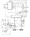
- a high-pressure fuel accumulator 1 is shown in the figure, via a delivery line 2 from a fuel pump 3, which sucks fuel from a fuel tank 4 with Fuel that is brought to high injection pressure is supplied becomes. There are pressures that essentially are above 1,000 bar.
- the pressure in the high-pressure fuel reservoir is detected by a pressure transmitter 6, the signal is supplied to a control device 7, through which Exceeding a fixed or one desired pressure, which depends on a particular Operating state of the associated internal combustion engine can, by a corresponding signal, a pressure control valve 9 is controlled. This is in one Fuel return line 10 from the high-pressure fuel accumulator to the fuel tank 4.
- each with one Fuel injector 14 are connected via the suitable time a desired amount of fuel can be injected into the internal combustion engine.
- the Control of fuel injection quantity according to time and Quantity also takes place via the control device 7 this control control signals according to the speed and the load under which the associated internal combustion engine to be operated receives.
- the control of this Fuel injection quantity takes place e.g. B. in a known manner through solenoid valves that connect the Control the high pressure accumulator and the injection valve. there Any fuel tax amounts that occur in the tank can also flow back via the return line 10 be returned to the tank.
- the fuel pump is z. B. in sync with that of the Fuel injector operated Internal combustion engine driven, that is at a speed that is also already detected to control the injection.
- the Fuel pump can also be separated by a special Drive can be operated, and the related Drive speed of the fuel pump is also detected be, e.g. B. by a speed sensor 15. With the help of this Drive speed and the fact that the fuel pump promotes a constant flow rate per revolution, lets now with the help of this speed Fuel high-pressure accumulator supplied amount of fuel capture so that on a measuring device for immediate Measurement of the amount of fuel delivered can be dispensed with can. But also when the fuel pump is off certain reasons with a variable funding volume works, the amount of fuel delivered by this can also from the control signals or by a Record the quantity measuring device.
- this crowd corresponding signal, added to one of the total fuel injection quantity corresponding in time unit, from the control device emitted signal is now using a comparison device 18 with the corresponding processed signal for the delivery rate of the delivery pump 3 compared from the speed signal. If there is a deviation from The amount of fuel supplied and discharged is now by the control device 7 a, triggered by the Comparison device 18, a signal for a display 20 or for an intervention in the operation of the Fuel injector issued. You can use this signal z. B. the drive of the fuel pump 3 be turned off or the entire fuel injector stopped in the internal combustion engine or reduced to emergency operation.
- the quantity measuring device 17 can be in a manner known per se a throttle inserted in the fuel return line 10 be provided and the pressure before and after the Throttle are compared to each other to get out of it To form quantity signal.
- Such measuring devices are e.g. in connection with injectors in the DE-A-3722264.
Landscapes
- Engineering & Computer Science (AREA)
- Chemical & Material Sciences (AREA)
- Combustion & Propulsion (AREA)
- Mechanical Engineering (AREA)
- General Engineering & Computer Science (AREA)
- Physics & Mathematics (AREA)
- General Physics & Mathematics (AREA)
- Electrical Control Of Air Or Fuel Supplied To Internal-Combustion Engine (AREA)
- Fuel-Injection Apparatus (AREA)
- Combined Controls Of Internal Combustion Engines (AREA)
Abstract
Description
Claims (5)
- Verfahren zum Betrieb einer Kraftstoffeinspritzeinrichtung, bei der Kraftstoff in meßbarer Menge unter Hochdruck in einen Hochdruckspeicher (1) gefördert wird, dessen Druck durch ein Drucksteuerventil (9) gesteuert wird und dass aus dem Hochdruckspeicher Kraftstoff zur Einspritzung über Einspritzventil (14) entnommen wird, dadurch gekennzeichnet, dass zur Erfassung der Dichtheit des Hochdruckspeichers (1) die dem Hochdruckspeicher zugeführte Kraftstoffmenge mit der von Hochdruckspeicher abgeführten Kraftstoffmenge verglichen wird und dass bei einer Abweichung der Mengen von einander eine Leckage erkannt und ein Signal zur Anzeige oder Betriebsbeeinflussung der Kraftstoffeinspritzeinrichtung erzeugt wird, wobei die dem Hochdruckbereich (1) zugeführte Kraftstoffmenge durch die Erfassung der Antriebsdrehzahl der den Kraftstoff auf Hochdruck mit geometrisch konstanter Fördermenge pro Umdrehung ihrer Antriebswelle fördernden Hochdruckförderpumpe (3) erfolgt, die Erfassung der Kraftstoffeinspritzmenge in der Zeiteinheit aus Signalen zur Steuerung der Einspritzmenge erfolgt und die Erfasssung der zur Einhaltung der Drucks im Hochdruckspeicher (1) aus diesem abgesteuerten Kraftstoffmenge durch eine die abgesteuerte Kraftstoffmenge erfassende Einrichtung erfolgt.
- Verfahren nach Anspruch 1, dadurch gekennzeichnet, dass die Erfassung der abgesteuerten Kraftstoffmenge durch eine die abgesteuerte Kraftstoffmenge messende Mengenmeßeinrichtung (17) erfolgt.
- Kraftstoffeinspritzeinrichtung zur Durchführung des Verfahrens nach Anspruch 2 mit einer Hochdruckförderpumpe (3), die auf ihre Antriebsdrehzahl bezogen mit konstanter, dieser Antriebsdrehzahl zugeordneter Föderrate Kraftstoff in einen Hochdruckspeicher (1) fördert, der über mehrere Druckleitungen (11) mit je einem Einspritzventil (14) verbunden ist, wobei der Zufluß zu den einzelnen Einspritzventilen (14) durch elektrisch gesteuerte Ventile erfolgt und der Hochdruckspeicher (1) ferner über eine ein in Abhängigkeit vom Druck im Hochdruckspeicher gesteuertes Drucksteuerventil (9) aufweisende Kraftstoffrücklaufleitung (10) entlastbar ist, dadurch gekennzeichnet, dass in der Kraftstoffrücklaufleitung (10) ein Durchflußmengenmeßgerät (17) angeordnet ist, das mit einer Steuereinrichtung (7, 7a, 18, 19) verbunden ist, die eine Einrichtung (19) zur Erfassung des von der Hochdruckförderpumpe (3) in einer Zeiteinheit geförderten Volumens, und mit einer Einrichtung (7) zur Erfassung der in der Zeiteinheit eingespritzten Kraftstoffmenge und einer Vergleichseinrichtung (18) zur Ermittlung einer Differenz zwischen der in den Hochdruckspeicher geförderten Kraftstoffmenge und der Summe der vom Durchflußmengenmeßgerät erfaßten Kraftstoffmengen und der in der Zeiteinheit eingespritzten Kraftstoffmenge und zur Bildung eines Signals zur Anzeige oder Betriebsbeeinflussung der Kraftstoffeinspritzeinrichtung bei Auftreten einer Differenz.
- Kraftstoffeinspritzeinrichtung nach Anspruch 3, dadurch gekennzeichnet, dass die Steuereinrichtung (7,7a) eine Signale für die geforderte Last (QK) und Signale für die Drehzahl (n) der Brennkraftmaschine aus einer Drehzahlsignalquelle erhaltende Kraftstoffmengensteuereinrichtung aufweist, durch die Steuersignale zur Steuerung der elektrisch gesteuerten Einspritzventile (14) erzeugt werden und diese Signale zur Erfassung der für die Einspritzung vom Hochdruckspeicher abgeführten Kraftstoffmenge der Vergleichseinrichtung (18) zugeführt werden, die ferner Signale von einer Einrichtung (19) erhält, die mit der Drehzahlsignalquelle oder mit einem Drehzahlgeber (15) der wenigstens mittelbar die Antriebsdrehzahl der Hochdruckförderpumpe erfaßt, zur Erfassung des von der Förderpumpe geförderten Volumens verbundenen ist.
- Kraftstoffeinspritzeinrichtung nach Anspruch 3 oder 4, dadurch gekennzeichnet, dass das Durchflußmengenmeßgerät eine Durchflußdrossel aufweist, die in der Kraftstoffrücklaufleitung angeordnet ist und mit einer Meßeinrichtung des an ihr anstehenden Druckgefälles als Maß für die Durchflußmenge.
Applications Claiming Priority (3)
| Application Number | Priority Date | Filing Date | Title |
|---|---|---|---|
| DE19534051 | 1995-09-14 | ||
| DE19534051A DE19534051A1 (de) | 1995-09-14 | 1995-09-14 | Verfahren zum Betrieb einer Kraftstoffeinspritzeinrichtung |
| PCT/DE1996/000985 WO1997010423A1 (de) | 1995-09-14 | 1996-06-05 | Verfahren zum betrieb einer kraftstoffeinspritzeinrichtung |
Publications (2)
| Publication Number | Publication Date |
|---|---|
| EP0792412A1 EP0792412A1 (de) | 1997-09-03 |
| EP0792412B1 true EP0792412B1 (de) | 2001-10-04 |
Family
ID=7772137
Family Applications (1)
| Application Number | Title | Priority Date | Filing Date |
|---|---|---|---|
| EP96919630A Expired - Lifetime EP0792412B1 (de) | 1995-09-14 | 1996-06-05 | Verfahren zum betrieb einer kraftstoffeinspritzeinrichtung und kraftstoffeinspritzeinrichtung |
Country Status (8)
| Country | Link |
|---|---|
| US (1) | US5738063A (de) |
| EP (1) | EP0792412B1 (de) |
| JP (1) | JP3966388B2 (de) |
| KR (1) | KR970707371A (de) |
| DE (2) | DE19534051A1 (de) |
| ES (1) | ES2165503T3 (de) |
| RU (1) | RU2161716C2 (de) |
| WO (1) | WO1997010423A1 (de) |
Families Citing this family (22)
| Publication number | Priority date | Publication date | Assignee | Title |
|---|---|---|---|---|
| DE19548278B4 (de) * | 1995-12-22 | 2007-09-13 | Robert Bosch Gmbh | Verfahren und Vorrichtung zur Steuerung einer Brennkraftmaschine |
| US5685268A (en) * | 1996-05-20 | 1997-11-11 | Siemens Automotive Corporation | Fuel leakage detector system |
| DE59705538D1 (de) * | 1996-06-26 | 2002-01-10 | Bosch Gmbh Robert | Verfahren zum betrieb einer kraftstoffeinspritzeinrichtung |
| DE19651671C2 (de) * | 1996-12-12 | 2001-10-04 | Daimler Chrysler Ag | Steuerung einer Einspritzanlage für eine mehrzylindrige Brennkraftmaschine |
| DE19703891B4 (de) * | 1997-02-03 | 2008-07-31 | Robert Bosch Gmbh | Verfahren und Vorrichtung zur Erkennung einer Leckage |
| JP3680515B2 (ja) * | 1997-08-28 | 2005-08-10 | 日産自動車株式会社 | 内燃機関の燃料系診断装置 |
| DE19738502A1 (de) * | 1997-09-03 | 1999-03-04 | Bosch Gmbh Robert | System zur Hochdruckerzeugung |
| DE19739653A1 (de) * | 1997-09-10 | 1999-03-11 | Bosch Gmbh Robert | Verfahren zum Erzeugen von unter Hochdruck stehendem Kraftstoff sowie System zur Kraftstoffhochdruckerzeugung |
| DE19822164A1 (de) * | 1998-05-16 | 1999-11-18 | Audi Ag | Kraftstoffversorgungssystem für eine Brennkraftmaschine |
| DE19927804A1 (de) * | 1999-06-18 | 2000-12-28 | Bosch Gmbh Robert | Kraftstoffversorgungsanlage für eine Brennkraftmaschine |
| DE19928548A1 (de) * | 1999-06-22 | 2001-01-04 | Hydraulik Ring Gmbh | Verfahren zur Erfassung einer Leckage |
| US6866025B1 (en) * | 1999-11-18 | 2005-03-15 | Siemens Vdo Automotive Corp. | High pressure fuel pump delivery control by piston deactivation |
| US6408821B1 (en) | 2000-12-19 | 2002-06-25 | Caterpillar Inc. | Fuel injection system with common actuation device and engine using same |
| DE10148649C1 (de) * | 2001-10-02 | 2003-08-07 | Bosch Gmbh Robert | Verfahren sowie Steuer und/oder Regelgerät zum Betreiben einer Brennkraftmaschine, sowie Brennkraftmaschine |
| US6715468B2 (en) * | 2001-11-07 | 2004-04-06 | Denso Corporation | Fuel injection system |
| JP4222097B2 (ja) * | 2002-06-10 | 2009-02-12 | 日産自動車株式会社 | 内燃機関の燃料系診断装置 |
| DE102004028515B3 (de) * | 2004-06-11 | 2005-11-24 | Siemens Ag | Verfahren und Vorrichtung zum Überwachen einer Kraftstoffzuführeinrichtung einer Brennkraftmaschine |
| RU2311557C2 (ru) * | 2005-12-06 | 2007-11-27 | Рязанский военный автомобильный институт | Способ определения проходных сечений распылителя |
| US7950371B2 (en) * | 2009-04-15 | 2011-05-31 | GM Global Technology Operations LLC | Fuel pump control system and method |
| US9133783B2 (en) * | 2012-03-07 | 2015-09-15 | Ford Global Technologies, Llc | Method and system for estimating fuel system integrity |
| CN106153266B (zh) * | 2016-06-29 | 2018-11-16 | 无锡职业技术学院 | 一种喷油器的微泄漏测试及密封性试验系统 |
| EP3592966B1 (de) * | 2017-03-06 | 2021-06-09 | HELLA GmbH & Co. KGaA | Spülpumpensystem mit notstopp |
Citations (1)
| Publication number | Priority date | Publication date | Assignee | Title |
|---|---|---|---|---|
| DE1922986A1 (de) * | 1969-05-06 | 1971-01-21 | Erdoel Raffinerie Mannheim Gmb | Verfahren zum schnellen Erkennen einer Leckage beim Transport von Fluessigkeiten in Rohrleitungen |
Family Cites Families (16)
| Publication number | Priority date | Publication date | Assignee | Title |
|---|---|---|---|---|
| IT1155953B (it) * | 1982-09-28 | 1987-01-28 | Weber Spa | Sistema di iniezione elettronica del combustibile per motori a combustione interna |
| SU1312226A1 (ru) * | 1985-04-26 | 1987-05-23 | Коломенский Филиал Всесоюзного Заочного Политехнического Института | Устройство дл впрыскивани топлива в дизель |
| SU1344931A1 (ru) * | 1985-06-03 | 1987-10-15 | Коломенский Филиал Всесоюзного Заочного Политехнического Института | Система впрыска топлива |
| SU1366677A1 (ru) * | 1985-12-16 | 1988-01-15 | Коломенский Филиал Всесоюзного Заочного Политехнического Института | Система впрыска топлива в дизель |
| US5197438A (en) * | 1987-09-16 | 1993-03-30 | Nippondenso Co., Ltd. | Variable discharge high pressure pump |
| JP3033214B2 (ja) * | 1991-02-27 | 2000-04-17 | 株式会社デンソー | 複数の燃料圧送手段による蓄圧式燃料供給方法及び装置と、複数の流体圧送手段を有する機器における異常判断装置 |
| JP3147460B2 (ja) * | 1991-04-26 | 2001-03-19 | 株式会社デンソー | 内燃機関の燃料噴射装置 |
| JPH0569374U (ja) * | 1992-02-28 | 1993-09-21 | 富士重工業株式会社 | 筒内直噴式エンジンの異常警告装置 |
| JP3345933B2 (ja) * | 1993-01-19 | 2002-11-18 | 株式会社デンソー | 蓄圧式燃料噴射装置 |
| DE4306252C1 (de) * | 1993-03-01 | 1994-05-19 | Daimler Benz Ag | Verfahren zum Betreiben einer luftverdichtenden mehrzylindrigen Einspritzbrennkraftmaschine |
| DE4313852B4 (de) * | 1993-04-28 | 2004-11-25 | Robert Bosch Gmbh | Kraftstoffeinspritzeinrichtung für Brennkraftmaschinen |
| IT1261575B (it) * | 1993-09-03 | 1996-05-23 | Fiat Ricerche | Metodo di diagnosi di malfunzionamenti del circuito ad alta pressione di impianti di iniezione ad alta pressione per motori a combustione interna |
| DE4330855C1 (de) * | 1993-09-11 | 1994-10-13 | Technoflow Tube Systems Gmbh | Verwendung eines Kunststoffrohres als crashgesicherte Kraftfahrzeug-Kraftstoffleitung |
| DE4335171C1 (de) * | 1993-10-15 | 1995-05-04 | Daimler Benz Ag | Kraftstoffeinspritzanlage für eine mehrzylindrige Dieselbrennkraftmaschine |
| JP3133586B2 (ja) * | 1993-11-18 | 2001-02-13 | 富士重工業株式会社 | 高圧燃料噴射式エンジンの燃料圧力制御装置 |
| JP3435770B2 (ja) * | 1993-12-03 | 2003-08-11 | 株式会社デンソー | 高圧燃料噴射装置 |
-
1995
- 1995-09-14 DE DE19534051A patent/DE19534051A1/de not_active Withdrawn
-
1996
- 1996-06-05 EP EP96919630A patent/EP0792412B1/de not_active Expired - Lifetime
- 1996-06-05 ES ES96919630T patent/ES2165503T3/es not_active Expired - Lifetime
- 1996-06-05 WO PCT/DE1996/000985 patent/WO1997010423A1/de not_active Ceased
- 1996-06-05 DE DE59607827T patent/DE59607827D1/de not_active Expired - Lifetime
- 1996-06-05 KR KR1019970703206A patent/KR970707371A/ko not_active Ceased
- 1996-06-05 RU RU97109815/06A patent/RU2161716C2/ru not_active IP Right Cessation
- 1996-06-05 JP JP51153497A patent/JP3966388B2/ja not_active Expired - Fee Related
-
1997
- 1997-06-05 US US08/836,585 patent/US5738063A/en not_active Expired - Lifetime
Patent Citations (1)
| Publication number | Priority date | Publication date | Assignee | Title |
|---|---|---|---|---|
| DE1922986A1 (de) * | 1969-05-06 | 1971-01-21 | Erdoel Raffinerie Mannheim Gmb | Verfahren zum schnellen Erkennen einer Leckage beim Transport von Fluessigkeiten in Rohrleitungen |
Also Published As
| Publication number | Publication date |
|---|---|
| JPH10509227A (ja) | 1998-09-08 |
| DE19534051A1 (de) | 1997-03-20 |
| RU2161716C2 (ru) | 2001-01-10 |
| US5738063A (en) | 1998-04-14 |
| EP0792412A1 (de) | 1997-09-03 |
| KR970707371A (ko) | 1997-12-01 |
| WO1997010423A1 (de) | 1997-03-20 |
| DE59607827D1 (de) | 2001-11-08 |
| JP3966388B2 (ja) | 2007-08-29 |
| ES2165503T3 (es) | 2002-03-16 |
Similar Documents
| Publication | Publication Date | Title |
|---|---|---|
| WO1997010423A1 (de) | Verfahren zum betrieb einer kraftstoffeinspritzeinrichtung | |
| DE69701523T2 (de) | Detektorsystem für kraftstoffleckagen | |
| EP0778922B1 (de) | Einrichtung zur erkennung eines lecks in einem kraftstoffversorgungssystem | |
| EP0748930A2 (de) | Verfahren zum Erkennen von Betriebsstörungen in einer Kraftstoffeinspritzanlage einer Brennkraftmaschine | |
| EP0819213A1 (de) | Einrichtung zur erkennung eines lecks in einem kraftstoffversorgungssystem | |
| DE19703891B4 (de) | Verfahren und Vorrichtung zur Erkennung einer Leckage | |
| DE102016200694A1 (de) | Verfahren zum Abgleichen eines Wasserdrucksensors einer Wassereinspritzvorrichtung und Wassereinspritzvorrichtung einer Brennkraftmaschine | |
| EP0846222B1 (de) | Verfahren zum betrieb einer kraftstoffeinspritzeinrichtung | |
| DE60115812T2 (de) | Vorrichtung zur Erkennung von Fehlern in einer Hochdruck-Kraftstoffeinspritzanlage | |
| WO2005001264A1 (de) | Verfahren zur diagnose eines volumenstromregelventils bei einer brennkraftmaschine mit hochdruck-speichereinspritzsystem | |
| DE102012102043B4 (de) | Diagnosevorrichtung für einen Kraftstoffinjektor | |
| DE102010060713B4 (de) | Fehlerdiagnosevorrichtung für ein Kraftstoffeinspritzsystem | |
| EP0764777B1 (de) | Verfahren und Vorrichtung zur Steuerung einer Brennkraftmaschine | |
| DE10257655A1 (de) | Akkumulations-Kraftstoffeinspritzvorrichtung | |
| DE102011075108A1 (de) | Verfahren zum Bestimmen einer Steuermenge eines Injektors | |
| DE102020205775A1 (de) | Vergleichen der Durchflussmengen von Einspritzventilen eines Verbrennungsmotors | |
| DE10318433B4 (de) | Kraftstoffeinspritzsystem mit Druckerhöhungsfunktion | |
| EP0982492A2 (de) | Vorrichtung zum Einspritzen von Brennstoff für eine Hubkolbenbrennkraftmaschine | |
| WO2006015893A1 (de) | Prüfverfahren | |
| WO1983000221A1 (fr) | Dispositif de mesure de la consommation de carburant d'un moteur a combustion interne | |
| DE102019220121A1 (de) | Verfahren und Vorrichtung zum Überprüfen der Funktionsfähigkeit einer Erdgas-Brennkraftmaschine | |
| DE19625487A1 (de) | Verfahren zum Betrieb einer Kraftstoffeinspritzeinrichtung | |
| DE102010004215A1 (de) | Vorrichtung zur Verhinderung des Absterbens des Motors bei einem mit einem Dieseleinspritzsystem ausgestatteten Fahrzeug | |
| DE102008017165B4 (de) | Verfahren zur Bestimmung der von einer Hochdruckpumpe geförderten Kraftstoffmenge und Einspritzanlage für eine Brennkraftmaschine | |
| DE19936102C1 (de) | Verfahren zur Überprüfung von in Common-Rail-Einspritzsystemen eingesetzten Einspritzinjektoren |
Legal Events
| Date | Code | Title | Description |
|---|---|---|---|
| PUAI | Public reference made under article 153(3) epc to a published international application that has entered the european phase |
Free format text: ORIGINAL CODE: 0009012 |
|
| AK | Designated contracting states |
Kind code of ref document: A1 Designated state(s): DE ES FR GB IT |
|
| 17P | Request for examination filed |
Effective date: 19970922 |
|
| 17Q | First examination report despatched |
Effective date: 19990304 |
|
| GRAG | Despatch of communication of intention to grant |
Free format text: ORIGINAL CODE: EPIDOS AGRA |
|
| RTI1 | Title (correction) |
Free format text: METHOD OF OPERATING A FUEL-INJECTION DEVICE AND FUEL-INJECTION DEVICE |
|
| GRAG | Despatch of communication of intention to grant |
Free format text: ORIGINAL CODE: EPIDOS AGRA |
|
| GRAH | Despatch of communication of intention to grant a patent |
Free format text: ORIGINAL CODE: EPIDOS IGRA |
|
| GRAH | Despatch of communication of intention to grant a patent |
Free format text: ORIGINAL CODE: EPIDOS IGRA |
|
| GRAA | (expected) grant |
Free format text: ORIGINAL CODE: 0009210 |
|
| AK | Designated contracting states |
Kind code of ref document: B1 Designated state(s): DE ES FR GB IT |
|
| REF | Corresponds to: |
Ref document number: 59607827 Country of ref document: DE Date of ref document: 20011108 |
|
| ET | Fr: translation filed | ||
| REG | Reference to a national code |
Ref country code: GB Ref legal event code: IF02 |
|
| GBT | Gb: translation of ep patent filed (gb section 77(6)(a)/1977) |
Effective date: 20011213 |
|
| REG | Reference to a national code |
Ref country code: ES Ref legal event code: FG2A Ref document number: 2165503 Country of ref document: ES Kind code of ref document: T3 |
|
| PGFP | Annual fee paid to national office [announced via postgrant information from national office to epo] |
Ref country code: ES Payment date: 20020626 Year of fee payment: 7 |
|
| PLBE | No opposition filed within time limit |
Free format text: ORIGINAL CODE: 0009261 |
|
| STAA | Information on the status of an ep patent application or granted ep patent |
Free format text: STATUS: NO OPPOSITION FILED WITHIN TIME LIMIT |
|
| 26N | No opposition filed | ||
| PG25 | Lapsed in a contracting state [announced via postgrant information from national office to epo] |
Ref country code: ES Free format text: LAPSE BECAUSE OF NON-PAYMENT OF DUE FEES Effective date: 20030606 |
|
| REG | Reference to a national code |
Ref country code: ES Ref legal event code: FD2A Effective date: 20030606 |
|
| PGFP | Annual fee paid to national office [announced via postgrant information from national office to epo] |
Ref country code: FR Payment date: 20110630 Year of fee payment: 16 |
|
| PGFP | Annual fee paid to national office [announced via postgrant information from national office to epo] |
Ref country code: GB Payment date: 20110621 Year of fee payment: 16 |
|
| PGFP | Annual fee paid to national office [announced via postgrant information from national office to epo] |
Ref country code: IT Payment date: 20110627 Year of fee payment: 16 |
|
| GBPC | Gb: european patent ceased through non-payment of renewal fee |
Effective date: 20120605 |
|
| PG25 | Lapsed in a contracting state [announced via postgrant information from national office to epo] |
Ref country code: IT Free format text: LAPSE BECAUSE OF NON-PAYMENT OF DUE FEES Effective date: 20120605 |
|
| REG | Reference to a national code |
Ref country code: FR Ref legal event code: ST Effective date: 20130228 |
|
| PG25 | Lapsed in a contracting state [announced via postgrant information from national office to epo] |
Ref country code: GB Free format text: LAPSE BECAUSE OF NON-PAYMENT OF DUE FEES Effective date: 20120605 Ref country code: FR Free format text: LAPSE BECAUSE OF NON-PAYMENT OF DUE FEES Effective date: 20120702 |
|
| PGFP | Annual fee paid to national office [announced via postgrant information from national office to epo] |
Ref country code: DE Payment date: 20130828 Year of fee payment: 18 |
|
| REG | Reference to a national code |
Ref country code: DE Ref legal event code: R119 Ref document number: 59607827 Country of ref document: DE |
|
| REG | Reference to a national code |
Ref country code: DE Ref legal event code: R119 Ref document number: 59607827 Country of ref document: DE Effective date: 20150101 |
|
| PG25 | Lapsed in a contracting state [announced via postgrant information from national office to epo] |
Ref country code: DE Free format text: LAPSE BECAUSE OF NON-PAYMENT OF DUE FEES Effective date: 20150101 |