EP0790414B1 - Ankerbolzen mit geschlitzter Spreizhülse - Google Patents
Ankerbolzen mit geschlitzter Spreizhülse Download PDFInfo
- Publication number
- EP0790414B1 EP0790414B1 EP97102209A EP97102209A EP0790414B1 EP 0790414 B1 EP0790414 B1 EP 0790414B1 EP 97102209 A EP97102209 A EP 97102209A EP 97102209 A EP97102209 A EP 97102209A EP 0790414 B1 EP0790414 B1 EP 0790414B1
- Authority
- EP
- European Patent Office
- Prior art keywords
- expansion sleeve
- anchoring bolt
- cone
- bolt according
- region
- Prior art date
- Legal status (The legal status is an assumption and is not a legal conclusion. Google has not performed a legal analysis and makes no representation as to the accuracy of the status listed.)
- Expired - Lifetime
Links
- 238000009760 electrical discharge machining Methods 0.000 claims abstract description 11
- 125000006850 spacer group Chemical group 0.000 claims description 9
- 238000004519 manufacturing process Methods 0.000 claims description 8
- 238000000034 method Methods 0.000 claims description 7
- 238000007373 indentation Methods 0.000 claims description 4
- 230000002093 peripheral effect Effects 0.000 claims description 4
- 238000003825 pressing Methods 0.000 claims description 4
- 238000004873 anchoring Methods 0.000 claims 21
- 239000002184 metal Substances 0.000 claims 1
- 238000003892 spreading Methods 0.000 abstract description 20
- 238000004049 embossing Methods 0.000 description 18
- 238000006073 displacement reaction Methods 0.000 description 5
- 239000011248 coating agent Substances 0.000 description 3
- 238000000576 coating method Methods 0.000 description 3
- 238000005452 bending Methods 0.000 description 2
- 230000000694 effects Effects 0.000 description 2
- 238000007514 turning Methods 0.000 description 2
- 230000015572 biosynthetic process Effects 0.000 description 1
- 239000006227 byproduct Substances 0.000 description 1
- 238000003754 machining Methods 0.000 description 1
- 230000014759 maintenance of location Effects 0.000 description 1
- 238000007788 roughening Methods 0.000 description 1
- 238000007493 shaping process Methods 0.000 description 1
- 230000003746 surface roughness Effects 0.000 description 1
Images

Classifications
-
- F—MECHANICAL ENGINEERING; LIGHTING; HEATING; WEAPONS; BLASTING
- F16—ENGINEERING ELEMENTS AND UNITS; GENERAL MEASURES FOR PRODUCING AND MAINTAINING EFFECTIVE FUNCTIONING OF MACHINES OR INSTALLATIONS; THERMAL INSULATION IN GENERAL
- F16B—DEVICES FOR FASTENING OR SECURING CONSTRUCTIONAL ELEMENTS OR MACHINE PARTS TOGETHER, e.g. NAILS, BOLTS, CIRCLIPS, CLAMPS, CLIPS OR WEDGES; JOINTS OR JOINTING
- F16B13/00—Dowels or other devices fastened in walls or the like by inserting them in holes made therein for that purpose
- F16B13/04—Dowels or other devices fastened in walls or the like by inserting them in holes made therein for that purpose with parts gripping in the hole or behind the reverse side of the wall after inserting from the front
- F16B13/06—Dowels or other devices fastened in walls or the like by inserting them in holes made therein for that purpose with parts gripping in the hole or behind the reverse side of the wall after inserting from the front combined with expanding sleeve
- F16B13/063—Dowels or other devices fastened in walls or the like by inserting them in holes made therein for that purpose with parts gripping in the hole or behind the reverse side of the wall after inserting from the front combined with expanding sleeve by the use of an expander
- F16B13/065—Dowels or other devices fastened in walls or the like by inserting them in holes made therein for that purpose with parts gripping in the hole or behind the reverse side of the wall after inserting from the front combined with expanding sleeve by the use of an expander fastened by extracting the screw, nail or the like
-
- F—MECHANICAL ENGINEERING; LIGHTING; HEATING; WEAPONS; BLASTING
- F16—ENGINEERING ELEMENTS AND UNITS; GENERAL MEASURES FOR PRODUCING AND MAINTAINING EFFECTIVE FUNCTIONING OF MACHINES OR INSTALLATIONS; THERMAL INSULATION IN GENERAL
- F16B—DEVICES FOR FASTENING OR SECURING CONSTRUCTIONAL ELEMENTS OR MACHINE PARTS TOGETHER, e.g. NAILS, BOLTS, CIRCLIPS, CLAMPS, CLIPS OR WEDGES; JOINTS OR JOINTING
- F16B2/00—Friction-grip releasable fastenings
- F16B2/005—Means to increase the friction-coefficient
Definitions
- the invention relates to a method for producing a Bolt anchor with slotted expansion sleeve, with a cone at its front end in the direction of impact for expansion the expansion sleeve, a rear carrying an external thread Section and a threadless middle section. Further The invention relates to a corresponding bolt anchor self.
- Such a bolt anchor is already known from EP 0 514 342 B1 known.
- To improve the expansion behavior of the expansion sleeve has at least two in on the outside Radially projecting in the longitudinal direction Retaining pin.
- To reduce the friction between the cone the bolt anchor and the expansion sleeve when setting the bolt anchor has a contact surface between the expansion sleeve and the outer contour of the bolt anchor has a friction-reducing coating on.
- this coating makes it more expensive Production of the bolt anchor.
- the object of the invention is an inexpensive method for producing a bolt anchor with a slotted expansion sleeve and to create an inexpensive bolt anchor that is characterized by good setting behavior.
- the surface the inside of the expansion sleeve at least in part has an increased roughness due to spark erosion is obtained.
- Another way to Creating this surface is an embossing tool to use a spark-eroded or etched surface having. The embossing tool comes with this surface pressed onto the surface of the inside. So on simple and inexpensive way to have a negative of the surface of the embossing tool on the inside of the expansion sleeve become. This second option is inexpensive in particular because it is usually used for production anyway an embossing tool is used for the expansion sleeve. Pressing the surface of the embossing tool into the Surface of the expansion sleeve is therefore a by-product of embossing process provided anyway.
- the invention also relates to a bolt anchor slotted expansion sleeve according to claim 3, wherein the bolt anchor its surface with increased roughness at least part of the inside of the expansion sleeve by spark erosion or pressing on a spark eroded or etched surface of an embossing tool, i.e. through can receive the steps previously explained.
- Spark erosion can be relatively uniform and achieve repeatable surface roughness without the This makes bolt anchors significantly more expensive.
- the inner diameter of the expansion sleeve is preferably through a bevel on the inside extends towards the cone, so that there is a better sliding behavior of the expansion sleeve on the cone when placing the bolt anchor. If in Area of this bevel, the inner surface increased Has roughness, is the setting behavior of the invention Bolt anchor particularly good because of the expansion process the expansion sleeve is started in the area of its bevel and the required pulling force at the start of the expansion process is higher.
- the setting behavior of the bolt anchor is further improved, by the expansion sleeve at least one radially inward has a head start. This will make the support surface between expansion sleeve and bolt anchor and thus the occurring Friction between these parts is reduced. Also this characteristic is based on the idea that by reduction the contact surface the friction between the expansion sleeve and Bolt anchor is reduced when setting.
- That is at least an inward projection a shape embossing what makes it particularly easy to manufacture.
- the at least one projection in the area of the cone facing away End of the expansion sleeve is shaped so that the associated End face of the expansion sleeve bulged at this point is.
- the shape is embossed so close to the rear Edge of the expansion sleeve that its face is no longer is flat, but has bulges. With that lies the Expansion sleeve no longer flat on a shoulder on the middle Section of the bolt anchor, which is their axial Movement movement when hammering limited. The axial This will play the expansion sleeve on the bolt anchor is reduced, and the expansion sleeve is set when the The bolt anchor is partially pulled out of the borehole, expanded earlier.
- the invention are on the outside the expansion sleeve in the area of the cone In the end, at least one radially projecting front Retaining pin and at least one axially spaced therefrom rear retaining pin provided.
- This holding pin protrude radially from the outer circumference of the cone and penetrate into a borehole when the bolt anchor is hammered in into a masonry.
- the provision of two holding pins increases the holding force of the expansion sleeve in the Masonry.
- the holding force can be increased again if, according to a preferred embodiment, the at least one front and a rear retaining pin angularly offset in the axial direction are arranged to each other, what with the bolt anchor according to EP 0 514 342 B1, this is precisely not the case. Due to the angular displacement of the front to the rear retaining pin it can not happen that the rear holding pin already in one during the impact process from the front retaining pin trough formed in the masonry comes to rest, whereby resulting from the rear retaining pin Holding force would decrease significantly. The reluctance of Expansion sleeve in the bolt anchor according to the invention is so again clearly improved.
- the rear retaining pin is preferably in the region of the Cone facing away from the end of the expansion sleeve. Further has the retaining pin according to the preferred embodiment a wedge shape created by embossing, the one better guidance behavior of the expansion sleeve when driving in in the masonry, for example with the rounded, sometimes even spherical design of the retaining pin is the case in EP 0 514 342 B1. Due to the wedge shape the lug digs less required Impact force a more or less deep linear Furrow in the masonry.
- the indentation is preferably at least partially bevelled or rounded towards the non-indented area.
- the expansion sleeve is usually with a continuous and at least one non-continuous axial slot provided so that there are so-called spreading lobes between the Slits result. Because the front retaining pin on spreading tabs is provided, is preferably the rear retaining pin in the axial direction in the area behind an axial not through slot arranged, which causes the angular displacement the holding pin is large to each other.
- a wedge-shaped rear retaining pin in the area of the axially continuous Slot divided in two so that a first part of the retaining pin on a perimeter end and a second part of the Retaining pin on the opposite circumferential end of the Expansion sleeve is provided.
- each Slot is a web-shaped, spacer reducing the width of the slot is provided through which the individual spreading lobes are more exact to each other are arranged. This also ensures that the shape of the expansion sleeve remains approximately cylindrical, even after hammering in the bolt anchor.
- This roughening the outer surface of the expansion sleeve is preferably carried out at least in the area of their end facing the cone Spark erosion.
- this area of Expanding sleeve also a negative of a spark-eroded surface one used to manufacture the expansion sleeve Be an embossing tool.
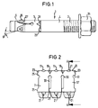
- a bolt anchor 1 in the direction of impact has a front end with a cone 5 which is a shaft region which cannot be seen in FIG. 1 with a reduced outer diameter to the an expansion sleeve 3 is arranged.
- the expansion sleeve 3 is produced by stamping a sheet, which is then processed.
- the continuous slot and the non-continuous Slits 33 result in three spreading lobes, one of which is denoted by 37.
- the spreading lugs 37 run, in plan view considered, slightly too at its front end. On the front End of that area of the spreading lugs 37 that still has parallel side surfaces, the spreading tabs 37 molded spacers 25, the slot 33 to the adjacent Significantly reduce spreading flap 37.
- the expansion sleeve 3 After the expansion sleeve 3 has been punched, it is embossed further edited. Doing the front, light tapered ends of the expansion tabs 37 in the area of Inside 7 of the expansion sleeve 3 with a visible in Fig. 3 Chamfer 9, which has a bevel angle ⁇ which corresponds to the cone angle ⁇ . In the area the bevel 9 receives the inside 7 of the expansion sleeve 3 by embossing an inner surface, which increases Roughness and a higher roughness than the rest Has inner surface of the expansion sleeve 3.
- the expansion sleeve 3 in this Machining area by spark erosion.
- the the Inside 7 of the expansion sleeve 3 with a rougher inner surface corresponding area 27 on an outer side 17 of the expansion sleeve 3 has an outer surface, which also is roughened by the correspondingly attacking embossing tool with a spark eroded surface in this area Is provided.
- the inside 7 and the outside 17 or an embossing tool in corresponding areas e.g. mechanically processed so that an increased Roughness on the inside 7 or the outside 17 of the Spreading sleeve 3 results.
- Each spreading flap 37 has in the middle in its front region to the spreading flap 37 itself, a front holding pin 15 the outside 17, which is formed by embossing, so that an indentation at the corresponding point on the inside 7 21 is present, at least partially and in particular at its rear end to the unenrolled Area is chamfered or rounded, so that the later setting the bolt anchor 1 a better sliding of the Spreading sleeve 3 on the cone 5 results.
- rear retaining pin 19 are provided, the protrude radially from the outside 17.
- Two retaining pins 19 are in the axial direction in the area behind an axially not through slot 33 arranged, whereas a rear Holding pin 23 divided into two by the continuous slot is so that a first part on a circumferential end and a second part of the holding pin 23 on the opposite Circumferential end is formed.
- the holding pins 15, 19 and 23 have a wedge shape when viewed from above and form, spatially, a partial pyramid or a partial cone.
- FIG. 4 shows the expansion sleeve 3 in partially bent condition.
- the bolt anchor 1 will for this purpose hammered into a borehole, the expansion sleeve 3 during turning due to their axial play to Bolt anchor 1 moves backwards until the projections 11 on Cast on paragraph 29.
- the protrusions 11 not only reduce the radial play of the expansion sleeve 3 to the bolt anchor 1, but also their axial play, so that the displacement of the Expansion sleeve 3 relative to the bolt anchor 1 when hammering in is low.
- the front Retaining pins 15 which press against the borehole wall, the spreading tabs 37 pressed radially inward so that the Slits in the area of the spacers partially disappear.
- the spreading tabs 37 do not become the bolt anchor 1 twisted and remain aligned parallel to each other.
- the holding pins dig 15, 19 and 23 partially in the masonry, whereby by their wedge shape achieves good guidance of the expansion sleeve 3 becomes.
- the split rear retaining pin presses when driving in 23 the opposite circumferential ends due to the wedge effect caused by its shape together, so that the continuous slot in the area of the spacer 25th also at least almost disappears.
- the expansion sleeve 3 is therefore less Outside diameter than when not hammered in.
Description
- Fig. 1
- eine Seitenansicht des erfindungsgemäßen Bolzenankers mit geschlitzter Spreizhülse,
- Fig. 2
- eine Draufsicht auf die Innenseite der noch nicht über den Bolzenanker zylindrisch geformten Spreizhülse nach Fig. 1,
- Fig. 3
- eine Schnittansicht nach der Linie A-A in Fig. 2, und
- Fig. 4
- die noch nicht vollständig zylindrisch gebogene Spreizhülse nach Fig. 2.
Claims (21)
- Verfahren zum Herstellen eines Bolzenankers mit geschlitzter Spreizhülse (3), die aus einem Blechteil gefertigt ist, wobei der Bolzenanker mit einem Konus (5) an seinem in Einschlagrichtung vorderen Ende zum Aufweiten der Spreizhülse (3), einem ein Außengewinde (2) tragenden hinteren Abschnitt und einem gewindelosen mittleren Abschnitt (4) versehen ist, dadurch gekennzeichnet, daß zumindest auf einem Teil der Oberfläche der Innenseite (7) der Spreizhülse (3) die Rauhigkeit der Oberfläche erhöht wird.
- Verfahren nach Anspruch 1, dadurch gekennzeichnet, daß der Teil der Oberfläche der Innenseite zur Erhöhung der Rauhigkeit funkenerodiert wird oder ein Prägewerkzeug mit einer funkenerodierten oder geätzten Oberfläche auf diesen Teil der Oberfläche der Innenseite (7) aufgepreßt wird.
- Verfahren nach Anspruch 1 oder 2, dadurch gekennzeichnet, daß die Spreizhülse (3) zumindest im Bereich (27) ihres dem Konus (5) zugewandten Endes eine Außenoberfläche hat, die durch Funkenerosion bearbeitet worden ist oder daß ein Prägewerkzeug mit funkenerodierter Oberfläche zur Schaffung eines Negativs auf der Oberfläche der Spreizhülse auf die Spreizhülse aufgepreßt wird.
- Bolzenanker mit geschlitzter Spreizhülse (3), mit einem Konus (5) an seinem in Einschlagrichtung vorderen Ende zum Aufweiten der Spreizhülse (3), einem ein Außengewinde (2) tragenden hinteren Abschnitt und einem gewindelosen mittleren Abschnitt (4), dadurch gekennzeichnet, daß eine Oberfläche mit erhöhter Rauhigkeit an zumindest einem Teil der Innenseite (7) der Spreizhülse (3) durch Funkenerosion oder durch Aufpressen einer funkenerodierten oder geätzten Oberfläche eines Prägewerkzeugs erhältlich ist.
- Bolzenanker nach Anspruch 4, dadurch gekennzeichnet, daß sich der Innendurchmesser der Spreizhülse (3) durch eine Abschrägung (9) an ihrer Innenseite (7) zum Konus (5) hin erweitert und im Bereich der Abschrägung (9) die Innenoberfläche mit erhöhter Rauhigkeit vorgesehen ist.
- Bolzenanker mit geschlitzter Spreizhülse (3) nach Anspruch 4 oder 5, wobei der Bolzenanker (1) an seinem in Einschlagrichtung vorderen Ende einen Konus (5) zum Aufweiten der Spreizhülse (3) sowie einen ein Außengewinde (2) tragenden hinteren Abschnitt und einen gewindelosen mittleren Abschnitt (4) aufweist, dadurch gekennzeichnet, daß die Spreizhülse (3) zumindest einen radial nach innen gerichteten Vorsprung (11) hat.
- Bolzenanker nach Anspruch 6, dadurch gekennzeichnet, daß der zumindest eine Vorsprung (11) eine Formprägung ist.
- Bolzenanker nach Anspruch 6 oder 7, dadurch gekennzeichnet, daß der zumindest eine Vorsprung (11) im Bereich des dem Konus (5) abgewandten Endes der Spreizhülse (3) so formgeprägt ist, daß die zugeordnete Stirnfläche (13) der Spreizhülse (3) an dieser Stelle ausgebuchtet ist.
- Bolzenanker nach einem der Ansprüche 6 bis 8, dadurch gekennzeichnet, daß zumindest drei am Umfang der Spreizhülse (3) gleichmäßig verteilte Vorsprünge (11) vorgesehen sind.
- Bolzenanker nach einem der Ansprüche 4 bis 9, dadurch gekennzeichnet, daß an der Außenseite (17) der Spreizhülse (3) im Bereich des dem Konus (5) zugewandten Endes zumindest ein radial nach außen abstehender vorderer Haltezapfen (15) und zumindest ein axial von diesem beabstandeter hinterer Haltezapfen (19, 23) vorgesehen sind.
- Bolzenanker nach Anspruch 10, dadurch gekennzeichnet, daß der zumindest eine vordere und zumindest eine hintere Haltezapfen (15, 19, 23) in axialer Richtung winkelversetzt zueinander angeordnet sind.
- Bolzenanker nach Anspruch 10 oder 11, dadurch gekennzeichnet, daß der hintere Haltezapfen (19, 23) im Bereich des dem Konus (5) abgewandten Endes der Spreizhülse (3) angeordnet ist.
- Bolzenanker nach einem der Ansprüche 10 bis 12, dadurch gekennzeichnet, daß die Haltezapfen (15, 19, 23) eine durch Formprägung entstandene Keilform aufweisen.
- Bolzenanker nach Anspruch 13, dadurch gekennzeichnet, daß eine durch die Formprägung der Haltezapfen (15, 19, 23) entstandene Einbuchtung (21) an der Innenseite (7) zumindest teilweise zum nicht eingebuchteten Bereich hin abgeschrägt oder abgerundet ist.
- Bolzenanker nach einem der Ansprüche 10 bis 14, dadurch gekennzeichnet, daß mehrere jeweils auf gleicher axialer Höhe liegende, auf einem Umfang gleichmäßig verteilte vordere und hintere Haltezapfen (15, 19, 23) vorgesehen sind.
- Bolzenanker nach einem der Ansprüche 10 bis 15, dadurch gekennzeichnet, daß der zumindest eine hintere Haltezapfen (19) in axialer Richtung im Bereich hinter einem axial nicht durchgehenden Schlitz (33) angeordnet ist.
- Bolzenanker nach einem der Ansprüche 10 bis 16, dadurch gekennzeichnet, daß ein keilförmiger hinterer Haltezapfen (23) im Bereich eines axial durchgehenden Schlitzes zweigeteilt ist und ein erster Teil des Haltezapfens (23) auf einem Umfangsende und ein zweiter Teil des Haltezapfens (23) auf dem gegenüberliegenden Umfangsende vorgesehen ist.
- Bolzenanker nach einem der Ansprüche 10 bis 17, dadurch gekennzeichnet, daß ein dem Konus (5) abgewandter äußerer Rand (35) der Haltezapfen (15, 19, 23) scharfkantig ausgebildet ist.
- Bolzenanker nach einem der Ansprüche 4 bis 18, dadurch gekennzeichnet, daß im Bereich jedes Schlitzes (33) ein in Umfangsrichtung wirkender, stegförmiger, die Breite des Schlitzes (33) verringernder Abstandhalter (25) vorgesehen ist.
- Bolzenanker nach einem der Ansprüche 4 bis 19, dadurch gekennzeichnet, daß die Außenoberfläche der Spreizhülse (3) zumindest teilweise angerauht ist.
- Bolzenanker nach Anspruch 20, dadurch gekennzeichnet, daß die Spreizhülse (3) zumindest im Bereich (27) ihres dem Konus (5) zugewandten Endes eine funkenerodierte Außenoberfläche aufweist oder daß mindestens dieser Bereich (27) ein Negativ einer funkenerodierten Oberfläche eines zur Herstellung der Spreizhülse (3) verwendeten Prägewerkzeugs ist.
Applications Claiming Priority (2)
| Application Number | Priority Date | Filing Date | Title |
|---|---|---|---|
| DE29602513U DE29602513U1 (de) | 1996-02-13 | 1996-02-13 | Bolzenanker mit geschlitzter Spreizhülse |
| DE29602513U | 1996-02-13 |
Publications (2)
| Publication Number | Publication Date |
|---|---|
| EP0790414A1 EP0790414A1 (de) | 1997-08-20 |
| EP0790414B1 true EP0790414B1 (de) | 2000-08-30 |
Family
ID=8019413
Family Applications (1)
| Application Number | Title | Priority Date | Filing Date |
|---|---|---|---|
| EP97102209A Expired - Lifetime EP0790414B1 (de) | 1996-02-13 | 1997-02-12 | Ankerbolzen mit geschlitzter Spreizhülse |
Country Status (4)
| Country | Link |
|---|---|
| EP (1) | EP0790414B1 (de) |
| AT (1) | ATE195996T1 (de) |
| DE (2) | DE29602513U1 (de) |
| ES (1) | ES2150712T3 (de) |
Cited By (1)
| Publication number | Priority date | Publication date | Assignee | Title |
|---|---|---|---|---|
| EP1892424A2 (de) * | 2006-08-23 | 2008-02-27 | HILTI Aktiengesellschaft | Spreizdübel |
Families Citing this family (10)
| Publication number | Priority date | Publication date | Assignee | Title |
|---|---|---|---|---|
| DE19621986B4 (de) * | 1996-04-04 | 2012-07-19 | Bts Gmbh & Co. Kg | Einschlagdübel |
| DE19728073A1 (de) * | 1997-04-21 | 1998-10-22 | Fischer Artur Werke Gmbh | Spreizdübel |
| DE29805837U1 (de) * | 1998-03-31 | 1999-08-05 | Fischer Artur Werke Gmbh | Spreizdübel |
| DE29917678U1 (de) | 1999-10-07 | 2000-02-17 | Berner Gmbh | Bolzenanker mit Spreizhülse |
| DE10157586A1 (de) | 2001-11-23 | 2003-06-05 | Hilti Ag | Bolzendübel mit Spreizkontrolle |
| DE10248664A1 (de) * | 2002-10-18 | 2004-04-29 | Fischerwerke Artur Fischer Gmbh & Co. Kg | Spreizanker und Verfahren zur Herstellung eines Spreizankers |
| US7811037B2 (en) | 2006-06-05 | 2010-10-12 | Illinois Tool Works Inc. | Anchor bolt and annularly grooved expansion sleeve assembly exhibiting high pull-out resistance, particularly under cracked concrete test conditions |
| WO2008022630A1 (de) * | 2006-08-22 | 2008-02-28 | Ccg-Concept Consulting Gmbh | Hülsenanker |
| CN107084175A (zh) * | 2017-03-10 | 2017-08-22 | 保能(天津)环保科技有限公司 | 一种膨胀锚栓以及墙体结构 |
| CN111501746A (zh) * | 2020-04-27 | 2020-08-07 | 辽宁沈通电力桩基础研发有限公司 | 岩石自锁锚杆 |
Family Cites Families (4)
| Publication number | Priority date | Publication date | Assignee | Title |
|---|---|---|---|---|
| US5076733A (en) * | 1990-05-04 | 1991-12-31 | Jennmar Corporation | Mine roof anchor assembly having an expansion shell assembly with a friction reducing means |
| US5190423A (en) * | 1991-02-15 | 1993-03-02 | Ewing Paul E | Locking fastener |
| DE4116149A1 (de) * | 1991-05-17 | 1992-11-19 | Hilti Ag | Spreizduebel mit reibungsmindernder beschichtung |
| DE4225869C2 (de) * | 1992-08-05 | 1997-12-04 | Itw Befestigungssysteme | Dübel |
-
1996
- 1996-02-13 DE DE29602513U patent/DE29602513U1/de not_active Expired - Lifetime
-
1997
- 1997-02-12 EP EP97102209A patent/EP0790414B1/de not_active Expired - Lifetime
- 1997-02-12 ES ES97102209T patent/ES2150712T3/es not_active Expired - Lifetime
- 1997-02-12 AT AT97102209T patent/ATE195996T1/de active
- 1997-02-12 DE DE59702261T patent/DE59702261D1/de not_active Expired - Lifetime
Cited By (2)
| Publication number | Priority date | Publication date | Assignee | Title |
|---|---|---|---|---|
| EP1892424A2 (de) * | 2006-08-23 | 2008-02-27 | HILTI Aktiengesellschaft | Spreizdübel |
| EP1892424A3 (de) * | 2006-08-23 | 2013-08-21 | HILTI Aktiengesellschaft | Spreizdübel |
Also Published As
| Publication number | Publication date |
|---|---|
| ES2150712T3 (es) | 2000-12-01 |
| ATE195996T1 (de) | 2000-09-15 |
| EP0790414A1 (de) | 1997-08-20 |
| DE59702261D1 (de) | 2000-10-05 |
| DE29602513U1 (de) | 1996-03-28 |
Similar Documents
| Publication | Publication Date | Title |
|---|---|---|
| DE2833077C2 (de) | ||
| DE4201016C2 (de) | ||
| DE69918078T2 (de) | Selbstfurchende schraube und rohling dafür | |
| DE19902461A1 (de) | Mutter mit T-förmigem Querschnitt | |
| DE69911404T2 (de) | Verfahren zur herstellen einer hülse | |
| DE1400883B1 (de) | Spanlos gewindeherstellende Schraube | |
| DE3623123A1 (de) | Selbstverstopfendes blind-befestigungselement | |
| EP0790414B1 (de) | Ankerbolzen mit geschlitzter Spreizhülse | |
| DE1954414A1 (de) | Befestigungselement | |
| DE4009690A1 (de) | Verfahren und vorrichtung zum herstellen von ankerschrauben fuer beton | |
| DE69608002T2 (de) | Verfahren zum Befestigen von Bauteilen einer Zusammenstellung | |
| DE3507966A1 (de) | Selbstverriegelndes blind-befestigungselement | |
| EP0665382A1 (de) | Spreizanker aus Metall und Verfahren zu dessen Herstellung | |
| DE2818588C3 (de) | Gewindeeinlage zur einseitigen Befestigung in Blechen | |
| DE3003140A1 (de) | Oese fuer eine verbindungsklemme und verfahren zu ihrer herstellung | |
| EP0225845A1 (de) | Spreizdübel mit Ansatz am Spreizelement | |
| EP0192914B1 (de) | Spreizdübel | |
| DE3444934C2 (de) | ||
| EP0099028B1 (de) | Schwerlast-Metalldübel | |
| DD294761A5 (de) | Verbindungselement und verfahren zur herstellung | |
| CH654080A5 (de) | Huelsenfoermiger spreizduebel. | |
| EP0636801A1 (de) | Sicherungsmutter | |
| DE3426288C2 (de) | Spreizdübel aus Metallblech | |
| EP3821143A1 (de) | Spreizanker | |
| DE3437846C2 (de) |
Legal Events
| Date | Code | Title | Description |
|---|---|---|---|
| PUAI | Public reference made under article 153(3) epc to a published international application that has entered the european phase |
Free format text: ORIGINAL CODE: 0009012 |
|
| AK | Designated contracting states |
Kind code of ref document: A1 Designated state(s): AT CH DE ES FR IT LI NL |
|
| 17P | Request for examination filed |
Effective date: 19980216 |
|
| 17Q | First examination report despatched |
Effective date: 19981118 |
|
| GRAG | Despatch of communication of intention to grant |
Free format text: ORIGINAL CODE: EPIDOS AGRA |
|
| GRAG | Despatch of communication of intention to grant |
Free format text: ORIGINAL CODE: EPIDOS AGRA |
|
| GRAH | Despatch of communication of intention to grant a patent |
Free format text: ORIGINAL CODE: EPIDOS IGRA |
|
| GRAH | Despatch of communication of intention to grant a patent |
Free format text: ORIGINAL CODE: EPIDOS IGRA |
|
| GRAA | (expected) grant |
Free format text: ORIGINAL CODE: 0009210 |
|
| AK | Designated contracting states |
Kind code of ref document: B1 Designated state(s): AT CH DE ES FR IT LI NL |
|
| REF | Corresponds to: |
Ref document number: 195996 Country of ref document: AT Date of ref document: 20000915 Kind code of ref document: T |
|
| REG | Reference to a national code |
Ref country code: CH Ref legal event code: EP |
|
| REF | Corresponds to: |
Ref document number: 59702261 Country of ref document: DE Date of ref document: 20001005 |
|
| REG | Reference to a national code |
Ref country code: CH Ref legal event code: NV Representative=s name: TROESCH SCHEIDEGGER WERNER AG |
|
| ITF | It: translation for a ep patent filed |
Owner name: STUDIO TORTA S.R.L. |
|
| REG | Reference to a national code |
Ref country code: ES Ref legal event code: FG2A Ref document number: 2150712 Country of ref document: ES Kind code of ref document: T3 |
|
| ET | Fr: translation filed | ||
| PLBQ | Unpublished change to opponent data |
Free format text: ORIGINAL CODE: EPIDOS OPPO |
|
| PLBI | Opposition filed |
Free format text: ORIGINAL CODE: 0009260 |
|
| 26 | Opposition filed |
Opponent name: FISCHERWERKE ARTUR FISCHER GMBH & CO.KG Effective date: 20010216 |
|
| NLR1 | Nl: opposition has been filed with the epo |
Opponent name: FISCHERWERKE ARTUR FISCHER GMBH & CO.KG |
|
| PLBF | Reply of patent proprietor to notice(s) of opposition |
Free format text: ORIGINAL CODE: EPIDOS OBSO |
|
| PLBF | Reply of patent proprietor to notice(s) of opposition |
Free format text: ORIGINAL CODE: EPIDOS OBSO |
|
| PLBF | Reply of patent proprietor to notice(s) of opposition |
Free format text: ORIGINAL CODE: EPIDOS OBSO |
|
| PLBO | Opposition rejected |
Free format text: ORIGINAL CODE: EPIDOS REJO |
|
| PLBN | Opposition rejected |
Free format text: ORIGINAL CODE: 0009273 |
|
| STAA | Information on the status of an ep patent application or granted ep patent |
Free format text: STATUS: OPPOSITION REJECTED |
|
| 27O | Opposition rejected |
Effective date: 20021209 |
|
| NLR2 | Nl: decision of opposition |
Effective date: 20021209 |
|
| PGFP | Annual fee paid to national office [announced via postgrant information from national office to epo] |
Ref country code: ES Payment date: 20090226 Year of fee payment: 13 |
|
| PGFP | Annual fee paid to national office [announced via postgrant information from national office to epo] |
Ref country code: NL Payment date: 20090226 Year of fee payment: 13 |
|
| PGFP | Annual fee paid to national office [announced via postgrant information from national office to epo] |
Ref country code: CH Payment date: 20090302 Year of fee payment: 13 |
|
| PLAB | Opposition data, opponent's data or that of the opponent's representative modified |
Free format text: ORIGINAL CODE: 0009299OPPO |
|
| REG | Reference to a national code |
Ref country code: NL Ref legal event code: V1 Effective date: 20100901 |
|
| REG | Reference to a national code |
Ref country code: CH Ref legal event code: PL |
|
| PG25 | Lapsed in a contracting state [announced via postgrant information from national office to epo] |
Ref country code: LI Free format text: LAPSE BECAUSE OF NON-PAYMENT OF DUE FEES Effective date: 20100228 Ref country code: CH Free format text: LAPSE BECAUSE OF NON-PAYMENT OF DUE FEES Effective date: 20100228 |
|
| PG25 | Lapsed in a contracting state [announced via postgrant information from national office to epo] |
Ref country code: NL Free format text: LAPSE BECAUSE OF NON-PAYMENT OF DUE FEES Effective date: 20100901 |
|
| PGFP | Annual fee paid to national office [announced via postgrant information from national office to epo] |
Ref country code: DE Payment date: 20110222 Year of fee payment: 15 Ref country code: AT Payment date: 20110314 Year of fee payment: 15 Ref country code: IT Payment date: 20110228 Year of fee payment: 15 Ref country code: FR Payment date: 20110302 Year of fee payment: 15 |
|
| REG | Reference to a national code |
Ref country code: ES Ref legal event code: FD2A Effective date: 20111118 |
|
| PG25 | Lapsed in a contracting state [announced via postgrant information from national office to epo] |
Ref country code: ES Free format text: LAPSE BECAUSE OF NON-PAYMENT OF DUE FEES Effective date: 20100213 |
|
| REG | Reference to a national code |
Ref country code: DE Ref legal event code: R082 Ref document number: 59702261 Country of ref document: DE Representative=s name: PRINZ & PARTNER PATENTANWAELTE RECHTSANWAELTE, DE |
|
| REG | Reference to a national code |
Ref country code: DE Ref legal event code: R082 Ref document number: 59702261 Country of ref document: DE Representative=s name: PRINZ & PARTNER MBB PATENTANWAELTE RECHTSANWAE, DE Effective date: 20120215 Ref country code: DE Ref legal event code: R082 Ref document number: 59702261 Country of ref document: DE Representative=s name: PRINZ & PARTNER PATENTANWAELTE RECHTSANWAELTE, DE Effective date: 20120215 Ref country code: DE Ref legal event code: R081 Ref document number: 59702261 Country of ref document: DE Owner name: BERNER TRADING HOLDING GMBH, DE Free format text: FORMER OWNER: BERNER GMBH, 74653 KUENZELSAU, DE Effective date: 20120215 |
|
| REG | Reference to a national code |
Ref country code: FR Ref legal event code: ST Effective date: 20121031 |
|
| PG25 | Lapsed in a contracting state [announced via postgrant information from national office to epo] |
Ref country code: IT Free format text: LAPSE BECAUSE OF NON-PAYMENT OF DUE FEES Effective date: 20120212 |
|
| REG | Reference to a national code |
Ref country code: AT Ref legal event code: MM01 Ref document number: 195996 Country of ref document: AT Kind code of ref document: T Effective date: 20120212 |
|
| REG | Reference to a national code |
Ref country code: DE Ref legal event code: R119 Ref document number: 59702261 Country of ref document: DE Effective date: 20120901 |
|
| PG25 | Lapsed in a contracting state [announced via postgrant information from national office to epo] |
Ref country code: FR Free format text: LAPSE BECAUSE OF NON-PAYMENT OF DUE FEES Effective date: 20120229 Ref country code: AT Free format text: LAPSE BECAUSE OF NON-PAYMENT OF DUE FEES Effective date: 20120212 |
|
| PG25 | Lapsed in a contracting state [announced via postgrant information from national office to epo] |
Ref country code: DE Free format text: LAPSE BECAUSE OF NON-PAYMENT OF DUE FEES Effective date: 20120901 |