EP0789857B1 - Systeme d'eclairage pour dispositif d'affichage a ecran plat - Google Patents
Systeme d'eclairage pour dispositif d'affichage a ecran plat Download PDFInfo
- Publication number
- EP0789857B1 EP0789857B1 EP96925943A EP96925943A EP0789857B1 EP 0789857 B1 EP0789857 B1 EP 0789857B1 EP 96925943 A EP96925943 A EP 96925943A EP 96925943 A EP96925943 A EP 96925943A EP 0789857 B1 EP0789857 B1 EP 0789857B1
- Authority
- EP
- European Patent Office
- Prior art keywords
- illumination system
- optical waveguide
- light
- polarizer
- reflector
- Prior art date
- Legal status (The legal status is an assumption and is not a legal conclusion. Google has not performed a legal analysis and makes no representation as to the accuracy of the status listed.)
- Expired - Lifetime
Links
Images

Classifications
-
- G—PHYSICS
- G02—OPTICS
- G02B—OPTICAL ELEMENTS, SYSTEMS OR APPARATUS
- G02B6/00—Light guides; Structural details of arrangements comprising light guides and other optical elements, e.g. couplings
- G02B6/0001—Light guides; Structural details of arrangements comprising light guides and other optical elements, e.g. couplings specially adapted for lighting devices or systems
- G02B6/0011—Light guides; Structural details of arrangements comprising light guides and other optical elements, e.g. couplings specially adapted for lighting devices or systems the light guides being planar or of plate-like form
- G02B6/0033—Means for improving the coupling-out of light from the light guide
- G02B6/0056—Means for improving the coupling-out of light from the light guide for producing polarisation effects, e.g. by a surface with polarizing properties or by an additional polarizing elements
-
- G—PHYSICS
- G02—OPTICS
- G02F—OPTICAL DEVICES OR ARRANGEMENTS FOR THE CONTROL OF LIGHT BY MODIFICATION OF THE OPTICAL PROPERTIES OF THE MEDIA OF THE ELEMENTS INVOLVED THEREIN; NON-LINEAR OPTICS; FREQUENCY-CHANGING OF LIGHT; OPTICAL LOGIC ELEMENTS; OPTICAL ANALOGUE/DIGITAL CONVERTERS
- G02F1/00—Devices or arrangements for the control of the intensity, colour, phase, polarisation or direction of light arriving from an independent light source, e.g. switching, gating or modulating; Non-linear optics
- G02F1/01—Devices or arrangements for the control of the intensity, colour, phase, polarisation or direction of light arriving from an independent light source, e.g. switching, gating or modulating; Non-linear optics for the control of the intensity, phase, polarisation or colour
- G02F1/13—Devices or arrangements for the control of the intensity, colour, phase, polarisation or direction of light arriving from an independent light source, e.g. switching, gating or modulating; Non-linear optics for the control of the intensity, phase, polarisation or colour based on liquid crystals, e.g. single liquid crystal display cells
- G02F1/133—Constructional arrangements; Operation of liquid crystal cells; Circuit arrangements
- G02F1/1333—Constructional arrangements; Manufacturing methods
- G02F1/1335—Structural association of cells with optical devices, e.g. polarisers or reflectors
-
- F—MECHANICAL ENGINEERING; LIGHTING; HEATING; WEAPONS; BLASTING
- F21—LIGHTING
- F21V—FUNCTIONAL FEATURES OR DETAILS OF LIGHTING DEVICES OR SYSTEMS THEREOF; STRUCTURAL COMBINATIONS OF LIGHTING DEVICES WITH OTHER ARTICLES, NOT OTHERWISE PROVIDED FOR
- F21V9/00—Elements for modifying spectral properties, polarisation or intensity of the light emitted, e.g. filters
- F21V9/14—Elements for modifying spectral properties, polarisation or intensity of the light emitted, e.g. filters for producing polarised light
-
- G—PHYSICS
- G02—OPTICS
- G02B—OPTICAL ELEMENTS, SYSTEMS OR APPARATUS
- G02B5/00—Optical elements other than lenses
- G02B5/02—Diffusing elements; Afocal elements
- G02B5/0205—Diffusing elements; Afocal elements characterised by the diffusing properties
- G02B5/021—Diffusing elements; Afocal elements characterised by the diffusing properties the diffusion taking place at the element's surface, e.g. by means of surface roughening or microprismatic structures
- G02B5/0221—Diffusing elements; Afocal elements characterised by the diffusing properties the diffusion taking place at the element's surface, e.g. by means of surface roughening or microprismatic structures the surface having an irregular structure
-
- G—PHYSICS
- G02—OPTICS
- G02B—OPTICAL ELEMENTS, SYSTEMS OR APPARATUS
- G02B5/00—Optical elements other than lenses
- G02B5/02—Diffusing elements; Afocal elements
- G02B5/0273—Diffusing elements; Afocal elements characterized by the use
- G02B5/0284—Diffusing elements; Afocal elements characterized by the use used in reflection
-
- G—PHYSICS
- G02—OPTICS
- G02B—OPTICAL ELEMENTS, SYSTEMS OR APPARATUS
- G02B5/00—Optical elements other than lenses
- G02B5/30—Polarising elements
- G02B5/3025—Polarisers, i.e. arrangements capable of producing a definite output polarisation state from an unpolarised input state
- G02B5/3033—Polarisers, i.e. arrangements capable of producing a definite output polarisation state from an unpolarised input state in the form of a thin sheet or foil, e.g. Polaroid
-
- G—PHYSICS
- G02—OPTICS
- G02F—OPTICAL DEVICES OR ARRANGEMENTS FOR THE CONTROL OF LIGHT BY MODIFICATION OF THE OPTICAL PROPERTIES OF THE MEDIA OF THE ELEMENTS INVOLVED THEREIN; NON-LINEAR OPTICS; FREQUENCY-CHANGING OF LIGHT; OPTICAL LOGIC ELEMENTS; OPTICAL ANALOGUE/DIGITAL CONVERTERS
- G02F1/00—Devices or arrangements for the control of the intensity, colour, phase, polarisation or direction of light arriving from an independent light source, e.g. switching, gating or modulating; Non-linear optics
- G02F1/01—Devices or arrangements for the control of the intensity, colour, phase, polarisation or direction of light arriving from an independent light source, e.g. switching, gating or modulating; Non-linear optics for the control of the intensity, phase, polarisation or colour
- G02F1/13—Devices or arrangements for the control of the intensity, colour, phase, polarisation or direction of light arriving from an independent light source, e.g. switching, gating or modulating; Non-linear optics for the control of the intensity, phase, polarisation or colour based on liquid crystals, e.g. single liquid crystal display cells
- G02F1/133—Constructional arrangements; Operation of liquid crystal cells; Circuit arrangements
- G02F1/1333—Constructional arrangements; Manufacturing methods
- G02F1/1335—Structural association of cells with optical devices, e.g. polarisers or reflectors
- G02F1/1336—Illuminating devices
- G02F1/13362—Illuminating devices providing polarized light, e.g. by converting a polarisation component into another one
-
- G—PHYSICS
- G02—OPTICS
- G02B—OPTICAL ELEMENTS, SYSTEMS OR APPARATUS
- G02B6/00—Light guides; Structural details of arrangements comprising light guides and other optical elements, e.g. couplings
- G02B6/0001—Light guides; Structural details of arrangements comprising light guides and other optical elements, e.g. couplings specially adapted for lighting devices or systems
- G02B6/0011—Light guides; Structural details of arrangements comprising light guides and other optical elements, e.g. couplings specially adapted for lighting devices or systems the light guides being planar or of plate-like form
- G02B6/0033—Means for improving the coupling-out of light from the light guide
- G02B6/005—Means for improving the coupling-out of light from the light guide provided by one optical element, or plurality thereof, placed on the light output side of the light guide
- G02B6/0051—Diffusing sheet or layer
-
- G—PHYSICS
- G02—OPTICS
- G02F—OPTICAL DEVICES OR ARRANGEMENTS FOR THE CONTROL OF LIGHT BY MODIFICATION OF THE OPTICAL PROPERTIES OF THE MEDIA OF THE ELEMENTS INVOLVED THEREIN; NON-LINEAR OPTICS; FREQUENCY-CHANGING OF LIGHT; OPTICAL LOGIC ELEMENTS; OPTICAL ANALOGUE/DIGITAL CONVERTERS
- G02F1/00—Devices or arrangements for the control of the intensity, colour, phase, polarisation or direction of light arriving from an independent light source, e.g. switching, gating or modulating; Non-linear optics
- G02F1/01—Devices or arrangements for the control of the intensity, colour, phase, polarisation or direction of light arriving from an independent light source, e.g. switching, gating or modulating; Non-linear optics for the control of the intensity, phase, polarisation or colour
- G02F1/13—Devices or arrangements for the control of the intensity, colour, phase, polarisation or direction of light arriving from an independent light source, e.g. switching, gating or modulating; Non-linear optics for the control of the intensity, phase, polarisation or colour based on liquid crystals, e.g. single liquid crystal display cells
- G02F1/133—Constructional arrangements; Operation of liquid crystal cells; Circuit arrangements
- G02F1/1333—Constructional arrangements; Manufacturing methods
- G02F1/1335—Structural association of cells with optical devices, e.g. polarisers or reflectors
- G02F1/133528—Polarisers
- G02F1/133536—Reflective polarizers
-
- G—PHYSICS
- G02—OPTICS
- G02F—OPTICAL DEVICES OR ARRANGEMENTS FOR THE CONTROL OF LIGHT BY MODIFICATION OF THE OPTICAL PROPERTIES OF THE MEDIA OF THE ELEMENTS INVOLVED THEREIN; NON-LINEAR OPTICS; FREQUENCY-CHANGING OF LIGHT; OPTICAL LOGIC ELEMENTS; OPTICAL ANALOGUE/DIGITAL CONVERTERS
- G02F1/00—Devices or arrangements for the control of the intensity, colour, phase, polarisation or direction of light arriving from an independent light source, e.g. switching, gating or modulating; Non-linear optics
- G02F1/01—Devices or arrangements for the control of the intensity, colour, phase, polarisation or direction of light arriving from an independent light source, e.g. switching, gating or modulating; Non-linear optics for the control of the intensity, phase, polarisation or colour
- G02F1/13—Devices or arrangements for the control of the intensity, colour, phase, polarisation or direction of light arriving from an independent light source, e.g. switching, gating or modulating; Non-linear optics for the control of the intensity, phase, polarisation or colour based on liquid crystals, e.g. single liquid crystal display cells
- G02F1/133—Constructional arrangements; Operation of liquid crystal cells; Circuit arrangements
- G02F1/1333—Constructional arrangements; Manufacturing methods
- G02F1/1335—Structural association of cells with optical devices, e.g. polarisers or reflectors
- G02F1/133528—Polarisers
- G02F1/133543—Cholesteric polarisers
-
- G—PHYSICS
- G02—OPTICS
- G02F—OPTICAL DEVICES OR ARRANGEMENTS FOR THE CONTROL OF LIGHT BY MODIFICATION OF THE OPTICAL PROPERTIES OF THE MEDIA OF THE ELEMENTS INVOLVED THEREIN; NON-LINEAR OPTICS; FREQUENCY-CHANGING OF LIGHT; OPTICAL LOGIC ELEMENTS; OPTICAL ANALOGUE/DIGITAL CONVERTERS
- G02F1/00—Devices or arrangements for the control of the intensity, colour, phase, polarisation or direction of light arriving from an independent light source, e.g. switching, gating or modulating; Non-linear optics
- G02F1/01—Devices or arrangements for the control of the intensity, colour, phase, polarisation or direction of light arriving from an independent light source, e.g. switching, gating or modulating; Non-linear optics for the control of the intensity, phase, polarisation or colour
- G02F1/13—Devices or arrangements for the control of the intensity, colour, phase, polarisation or direction of light arriving from an independent light source, e.g. switching, gating or modulating; Non-linear optics for the control of the intensity, phase, polarisation or colour based on liquid crystals, e.g. single liquid crystal display cells
- G02F1/133—Constructional arrangements; Operation of liquid crystal cells; Circuit arrangements
- G02F1/1333—Constructional arrangements; Manufacturing methods
- G02F1/1335—Structural association of cells with optical devices, e.g. polarisers or reflectors
- G02F1/133528—Polarisers
- G02F1/13355—Polarising beam splitters [PBS]
Definitions
- the invention relates to an illumination system comprising an optical waveguide of an optically transparent material having an exit surface and a plurality of end faces, opposite at least one of which a light source is situated, whose light can be coupled in at said end face of the optical waveguide, and polarizing means for polarizing the light emitted by the light source.
- the invention also relates to a flat-panel picture display device comprising such an illumination system.
- a flat-panel picture display device which is provided with an illumination system of the type described in the opening paragraph is known from United States Patent US-A 4,212,048.
- a picture display panel is illuminated by means of an illumination system which consists of a wedge-shaped transparent plate and a light source.
- the light rays emitted by the light source are coupled in at the end face of the optical waveguide and propagate through the waveguide because they undergo total internal reflection at the interface between optical waveguide and air. Since the angle of incidence of the light rays on the waveguide-air interface decreases upon each reflection, this angle will be smaller at a given instant than the critical angle and the relevant light rays will leave the optical waveguide.
- the optical waveguide comprises polarizing means in the form of a strip of polarizing material which extends across the thickness of the optical waveguide in the vicinity of the light source. In this way, it is ensured that the light leaving the optical waveguide is polarized.
- a drawback of the illumination system described in said US Patent is that substantially 50% of the light supplied by the light source is lost without being able to contribute to the formation of the image, because the polarizer is dichroic and thus absorbs the unwanted direction of polarization.
- a further drawback is that the optical waveguide must be wedge-shaped in order that light can be coupled out at the exit surface of the optical waveguide. Due to the requirement of a sufficient light output, the freedom of design or the choice of the material for the optical waveguide is limited. In fact, a short time after the light is coupled into the optical waveguide, it reaches the polarizer and is thus polarized.
- This polarized light propagates through the optical waveguide until it is incident on the exit surface at an angle which is smaller than the critical angle for total internal reflection, and is consequently coupled out. Since, in practice, isotropic material is not perfectly isotropic, there will still be depolarization during propagation through the optical waveguide. Consequently, the output of polarized light having the same direction of polarization is reduced considerably. Either the distance which is covered before coupling out should therefore be relatively short, which limits the freedom of design of the optical waveguide, or the material of the optical waveguide should be very much isotropic, which limits the choice of the material.
- the illumination system according to the invention is characterized in that the polarizing means are constituted by a reflective polarizer which is present on the surface of the optical waveguide located opposite the exit surface of the optical waveguide, a surface of the polarizer remote from the optical waveguide being provided with a diffuser.
- the light emitted by the light source is unpolarized.
- this beam will be split up into two beam components having complementary states of polarization.
- the polarizer is a linear polarizer, the two beam components will have mutually perpendicular directions of polarization.
- the polarizer is a circular polarizer, a levorotatory circularly polarized beam component and a dextrorotatary circularly polarized beam component will be formed.
- the reflected beam component will be further referred to as the unwanted beam component.
- the other beam component in other words, the desired beam component, will be passed by the polarizer.
- the desired beam component is understood to mean the component having the state of polarization which will be supplied by the illumination system.
- the beam component which will be passed and the beam component which will be reflected is determined by the structure of the polarizer.
- the beam component reflected by the polarizer will further propagate in the optical waveguide and depolarize after having covered a given distance. This distance is dependent on the extent of birefringence of the material of the optical waveguide. After this distance, a part of this beam component will thus also have the desired direction of polarization and consequently be passed by the reflective polarizer towards the diffuser.
- the diffuser diffuses the beam incident thereon partly forwards and partly backwards.
- the forward-diffused light the greater part of which consists of light having the desired direction of polarization, is incident again on the reflective polarizer and will thus acquire a purer direction of polarization. In fact, the quantity of light which would still have the unwanted direction of polarization after the first passage, is now also reflected for the greater part.
- the direction of polarization of the desired beam component is enhanced. In this way, a better contrast is obtained in a picture display device in which this illumination system is used.
- This enhanced contrast could not be realized, for example, if the polarizer were not integrated with the optical waveguide but would be present above the waveguide, because the light emitted by the light source would then pass the polarizer only once.
- a reflective polarizer in itself has the advantage that substantially no light is absorbed by the polarizer so that there is substantially no heating.
- the integration of the polarizer in the optical waveguide ensures that the illumination system is relatively thin and that there is less unwanted light conductor and fewer reflection losses occur.
- a preferred embodiment of the illumination system according to the invention is characterized in that a reflector is arranged at the side of the diffuser remote from the reflective polarizer.
- the light having the unwanted direction of polarization and leaving the optical waveguide via the diffuser is reflected by this reflector towards the optical waveguide.
- the beam component having the desired direction of polarization is passed by the polarizer and subsequently coupled out via the exit surface, while the beam component having the unwanted direction of polarization is reflected again by the polarizer towards the diffuser.
- a further embodiment of the illumination system according to the invention is characterized in that the reflector is a polarization-rotating or depolarizing reflector.
- the polarization-rotating element is preferably a specular reflector.
- the direction of polarization of a circularly polarized beam is inverted at such a reflector.
- the polarization-rotating element may be, for example, a ⁇ /4 plate with a reflector arranged behind it.
- the reflector has a depolarizing effect
- the light having the unwanted direction of polarization passed by the polarizer is depolarized so that approximately half thereof immediately has the desired direction of polarization.
- This choice of polarizer is applicable to both linearly and circularly polarized light.
- the illumination system according to the invention is preferably characterized in that the reflector is a foil comprising particles which reflect substantially completely.
- a further embodiment of the illumination system according to the invention is characterized in that a reflector having a depolarizing effect is arranged on at least one end face remote from a light source.
- the reflectors at the end faces have a depolarizing effect, light incident thereon, which has a state of polarization which is unwanted to be coupled out at the exit surface, is depolarized, so that approximately half of this light immediately acquires the suitable direction of polarization and can be coupled out of the optical waveguide.
- the other half of the light will depolarize or not depolarize during propagation.
- the advantage of the depolarizing reflectors is that depolarization occurs independently of the extent of birefringence of the optical waveguide material.
- a first embodiment of the illumination system according to the invention is characterized in that the reflective polarizer is a cholesteric polarizer.
- a cholesteric polarizer is a polarizer comprising a layer of liquid crystalline material having a cholesteric ordering.
- a polarizer is particularly suitable as a reflective polarizer.
- the chiral molecules have such a structure that they spontaneously order in solution to a spiral or helix-like structure. This helix-like structure may be directed in such a way that the axis of the helix will be transverse to the layer.
- a further embodiment of the illumination system according to the invention is characterized in that the cholesteric polarizer is implemented as a single layer of a liquid crystalline polymer material, within which layer the pitch of the molecular helix varies substantially continuously between two values which correspond to the lower limit and the upper limit, respectively, of the reflection band required to cover the full visible wavelength range.
- a single-layer cholesteric polarizer is thinner than a multilayer stack in which each of the layers has a limited bandwidth.
- a further advantage of a pitch which is variable across the layer of the polarizer is that the reflection bandwidth can be chosen to be so wide that the band shift which occurs upon light incidence at a large angle with respect to the normal on the polarizer does not have any detrimental influence on the polarizing effect of the cholesteric layer.
- a further embodiment of the illumination system according to the invention is characterized in that the illumination system comprises an n. ⁇ /4 plate, in which n is an integral, odd number.
- the light supplied by the illumination system is linearly polarized
- the light passed by the cholesteric polarizer towards the exit surface of the optical waveguide is to be converted into linearly polarized light before it leaves the optical waveguide.
- This embodiment of the illumination system according to the invention is characterized in that the n. ⁇ /4 plate is present on the exit surface of the optical waveguide.
- a ⁇ /4 plate, particularly a wideband ⁇ /4 plate is very suitable for this purpose.
- a plate is known per se from, for example, the article: "Retardation Film for STN-LCDs 'NRF'" of the firm of Nitto Denko in SID '92 Exhibit Guide, Society for Information Display, May 17-22, 1992, Boston, Massachusetts, USA.
- the cholesteric layer may be a self-supporting film but may also be provided on a substrate. If the layer is provided on a substrate, an embodiment of the illumination system according to the invention may be characterized in that the n. ⁇ /4 plate is present between the cholesteric layer and the optical waveguide.
- the extra substrate may be dispensed with and the cholesteric layer may be provided on the ⁇ /4 plate which then functions as the substrate.
- n. ⁇ /4 plate functions as an optical waveguide.
- the illumination system instead of providing the illumination system with a separate optical waveguide and a separate polarization rotator, these two functions can be combined in a single element in the form of a ⁇ /4 plate.
- the illumination system may thus become even thinner.
- the reflective polarizer is a linear polarizer which is implemented as a stack of layers comprising a birefringent material or as a stack of layers being alternately birefringent and non-birefringent.
- the beam components are linearly polarized and a ⁇ /4 plate is consequently superfluous.
- Such a polarizer may be made by means of a single-step extrusion.
- An example of such a polarizer is described extensively in United States Patent US-A 5,217,794.
- a further embodiment of the illumination system according to the invention is characterized in that the diffuser is a thin film which is provided on the surface of the reflective polarizer.
- Such a film can be provided in a simple manner on the cholesteric layer or its substrate.
- Another embodiment of the illumination system according to the invention is characterized in that the diffuser is a light-diffusing structure provided in the surface of the reflective polarizer.
- a further embodiment of the illumination system according to the invention is characterized in that the light-diffusing structure is constituted by a pattern of discrete diffusing areas.
- the advantage of such a pattern is that its configuration can be adapted to the desired light distribution on the exit surface of the optical waveguide.
- the intensity will decrease as these areas are further remote from the light source.
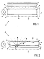
- the flat-panel picture display device 1 shown diagrammatically in Fig. 1 comprises an illumination system 3, a picture display panel 5 and an analyzer 7.
- the illumination system 3 comprises an optical waveguide 9 of an optically transparent material and a light source 11.
- the optical waveguide 9 has four end faces 13, 14, 15, 16, at least two of which face each other. At one of the end faces, for example, 13, the light from the light source 11 is coupled into the optical waveguide 9.
- the light source 11 may be, for example, a rod-shaped fluorescence lamp, or a light-emitting diode (LED) if the illumination system is used in flat-panel picture display devices with small picture display panels such as, for example, a cellular telephone.
- the optical waveguide may consist of a synthetic material, for example, PMMA or polycarbonate.
- the light source 11 is at least partly surrounded by a reflector 17 which ensures that light emitted by the light source 11 in a direction remote from the optical waveguide 9 is as yet sent towards the optical waveguide 9.
- the exit surface 19 of the optical waveguide 9 is directed towards the picture display panel 5.
- the picture display panel 5 may comprise, for example, a liquid crystalline material and be provided with a matrix of pixels whose operation may be based on the twisted nematic effect (TN), the supertwisted nematic effect (STN), or the ferroelectric effect so as to modulate the direction of polarization of light incident thereon.
- TN twisted nematic effect
- STN supertwisted nematic effect
- ferroelectric effect so as to modulate the direction of polarization of light incident thereon.
- the illumination system 3 comprises polarizing means.
- Fig. 2 shows an embodiment.
- the polarizing means are constituted by a reflective polarizer 21 in combination with a diffuser 23.
- the reflective polarizer 21 is integrated with the optical waveguide 9 and constitutes the surface 25 of the optical waveguide located opposite the exit surface 19.
- the diffuser 23 is present on the surface 25.
- Fig. 2 illustrates the beam path in the optical waveguide 9.
- An unpolarized light beam b emitted by the light source 11 is coupled into the optical waveguide 9 via the end face 13 and is incident on the reflective polarizer 21.
- This polarizer 21 will split up the incident beam b into two beam components b 1 , b 2 having complementary states of polarization.
- the polarization of the beam component b 1 passed by the polarizer 21 will further be referred to as the desired direction of polarization, because this beam component has the direction of polarization which will be supplied by the illumination system.
- the reflected beam component b 2 has the unwanted direction of polarization.
- the passed beam component b 1 reaches the diffuser 23 where it is partly diffused backwards, out of the illumination system 3, but mainly forwards towards the picture display panel 5.
- the light diffused towards the picture display panel 5 is incident again on the reflective polarizer 21 which will pass the desired direction of polarization towards the picture display panel 5 and reflect the unwanted direction of polarization back to the diffuser 23.
- the diffuser 23 preferably maintains the polarization. In that case, the polarization of the desired beam component will be enhanced upon the second passage through the polarizer 21.
- the unwanted beam component b 2 which is reflected into the optical waveguide by the polarizer 21 further propagates through the optical waveguide 9 and will depolarize after some time, dependent on the birefringence of the material of the optical waveguide 9. In this way, at least a part of this beam component acquires the suitable direction of polarization to be coupled out of the optical waveguide 9.
- a reflector 27 is arranged at the side of the diffuser 23 remote from the polarizer 21. This reflector 27 ensures that light leaving the illumination system 3 at the side remote from the picture display panel 5 is reflected towards the optical waveguide 9 so as to be coupled in again.
- the reflector 27 may be, for example, an aluminium foil.
- the reflector 27 is preferably implemented as a foil which comprises particles showing hardly any or no absorption.
- the particles may be, for example, BaSO 4 or TiO 2 .
- the reflective polarizer 21 is integrated in the optical waveguide 9 and there is no interspace between these components, so that the picture display device 1 may be implemented in a very thin form. Due to the integration with the optical waveguide 9, there will be a relatively small loss of light as a result of unwanted light conduction and unwanted reflections.
- the reflective polarizer 21 may be implemented in different ways.
- the polarizer comprises a layer of liquid crystalline material having a cholesteric ordering.
- the chiral molecules have such a structure that they spontaneously order in solution to a spiral or helix-like structure having a pitch p. This helix-like structure may be directed in such a way that the axis of the helix will be transverse to the layer.
- p is the pitch of the molecular helix
- n o and n e are the ordinary and the extraordinary refractive index, respectively, of the liquid crystalline material.
- the cholesteric polarizer may be composed of a plurality of layers within which the pitch is constant, but in which each layer is active in a different wavelength range.
- the different wavelength ranges may be chosen to be such that all layers combined cover the full visible wavelength range. In this way, it is possible to use the illumination system in a colour picture display device.
- the cholesteric polarizer preferably consists of a single layer of liquid crystalline polymer material in which the pitch of the molecular helix varies substantially continuously between two values which correspond to the lower limit and the upper limit, respectively, of the reflection band which is required to cover the full visible wavelength range (between 400 and 780 nm). In this way, it is sufficient to use a much thinner polarizer than in the case of stacked layers.
- a further advantage is that a single-layer polarizer has a better optical quality. The quality for cholesteric polarizers decreases with an increasing number of layers due to errors which are typical of cholesterics. Moreover, the range of angles of incidence of light to be polarized, within which the polarizer is effective, decreases with an increasing thickness.
- An advantage of a polarizer consisting of a single cholesteric layer is that the bandwidth can be chosen to be such that the band shift which occurs upon light incidence at a large angle with respect to the normal to the polarizer has no detrimental influence on the polarizing effect. In fact, with a non-perpendicular incidence on the cholesteric layer, there is an extra birefringence which increases with an increasing angle of incidence.
- the bandwidth of the polarizer should range between 400 and 890 nm.
- a cholesteric polarizer Another possibility of manufacturing a cholesteric polarizer is to stack a plurality of cholesteric layers, at least a number of which have a pitch continuously varying across the layer thickness. In this way, it is sufficient to use a much smaller number of layers than in the first- mentioned case.
- cholesteric layers are suitable as polarizers.
- Cholesteric polarizers are known, for example, from the article "Polarizing Color Filters made from Cholesteric LC Silicones" by R. Maurer et al. in SID International Symposium 1990, Digest of Technical Papers, pp. 110-113.
- the reflective polarizer may be implemented as a linear polarizer comprising a stack of birefringent layers or a stack of layers being alternately birefringent and non-birefringent.
- the illumination system 3 should further comprise a ⁇ /4 plate 29 which preferably has a wide bandwidth.
- a wideband ⁇ /4 plate is a transparent element which is composed of, for example, different layers and realizes such a phase rotation in a beam for all wavelengths in the visible wavelength range that circularly polarized light is converted into linearly polarized light.
- a ⁇ /4 plate is known, for example, from the article "Retardation Film for STN-LCDs 'NRF'" of the firm of Nitto Denko in SID '92 Exhibit Guide, Society for Information Display, May 17-22, 1992, Boston, Massachusetts, USA.
- the ⁇ /4 plate 29 may be present on the exit surface 19 of the optical waveguide 9, as is shown in Fig. 2. If the cholesteric layer should be provided on a separate substrate, the ⁇ /4 plate 29 may be present between the substrate and the cholesteric layer instead of on the exit face 19 of the optical waveguide 9. Instead of a separate substrate, the ⁇ /4 plate 29 may function as a substrate to be provided with the cholesteric layer.
- the diffuser 23 may also be implemented in different manners.
- the diffuser 23 may be provided as a thin film on the surface of the reflective polarizer 21.
- the desired diffusing structure can be provided in the surface of the polarizer, for example, by means of a hot die or by means of a replica technique. Another possibility is to mechanically roughen the surface of the polarizer.
- a flat-panel picture display device comprises diffusing means for spreading the intensity across the exit surface 19 of the optical waveguide 9.
- the configuration of the pattern can be adapted in such a way that the intensity distribution of the light supplied by the illumination system 3 is homogeneous across the exit surface 19.
- the light coupled out at the exit surface 19 originates from diffusing areas which are further remote from the end face via which the light was coupled into the optical waveguide 9, its intensity decreases. This phenomenon can be compensated for by increasing the density of the light-diffusing areas as the distance to the light source increases.
- This principle is already known from hitherto known flat-panel picture display devices using conventional absorbing polarizers. An example is described in United States Patent US-A 4,985,809.
- a light source 11 may also be provided at the opposite end face 15 so as to achieve a greater luminance. It is also possible to provide a light source at a third end face 14 and possibly at a fourth end face 16.
- a single rod-shaped lamp 6, 8 having a number of bends may be used to illuminate three or four end faces, instead of providing a separate light source per end face. The efficiency of the illumination system is consequently enhanced. Said possibilities are illustrated in Figs. 3a to 3d.
- each end face on which no light source is present may be provided with a reflector 31 so as to keep the light arriving there in the optical waveguide 9 and still enable it to be coupled out towards the picture display panel 5 with the desired direction of polarization.
- This reflector preferably has a depolarizing effect. Light having the unwanted direction of polarization reaching the reflector will then be depolarized so that approximately half thereof will immediately acquires the suitable direction of polarization. If the reflector does not depolarize, the depolarization depends on the extent of birefringence of the material constituting the optical waveguide.
- an extra polarizer may be arranged at the side of the illumination system facing the picture display panel, so as to obstruct the passage of light having the unwanted direction of polarization to the picture display panel. If this polarizer is a reflecting polarizer, the reflected light can be recuperated in the illumination system and there is substantially no loss of light.
- the illumination system 3 may be provided with an element 33 concentrating the radiation to a beam (see Fig. 1).
- This element 33 may be implemented, for example, as a one-dimensional or two-dimensional prism structure.
- the light exiting from the illumination system can then be concentrated to a beam within an angle which is smaller than the angle within which the light leaves the optical waveguide, resulting in an increase of the brightness within a given viewing angle.
- the angular area in which the light is concentrated to a beam, and thus the viewing angle within which a great brightness is desired, is determined by the angles of inclination of the prism edges and by the refractive index of the material of the element 33.
- the use of such a radiation-concentrating element in flat-panel picture display devices is known, for example, from the English language abstract of JP-A 2-257188.
Claims (16)
- Système d'éclairage (3) comprenant un guide d'ondes optique (9) constitué d'un matériau optiquement transparent ayant une surface de sortie (19) et une pluralité de faces terminales (13, 14, 15, 16), à l'opposite d'au moins une se situe une source de lumière (11) dont la lumière peut être introduite par couplage à une face terminale (13) du guide d'ondes optique, et des moyens polarisants qui font corps avec le guide d'ondes optique pour polariser la lumière qui est émise par la source de lumière, caractérisé en ce que les moyens polarisants sont constitués par un polariseur réflectif (21) étant présent sur une surface (25) du guide d'ondes optique qui se situe à l'opposite de la surface de sortie du guide d'ondes optique, une surface du polariseur s'éloignant du guide d'ondes optique étant pourvue d'un diffuseur (23).
- Système d'éclairage selon la revendication 1, caractérisé en ce qu'un réflecteur est disposé du côté du diffuseur s'éloignant du polariseur réflectif.
- Système d'éclairage selon la revendication 2, caractérisé en ce que le réflecteur est un réflecteur à rotation de polarisation ou de dépolarisation.
- Système d'éclairage selon la revendication 2 ou 3, caractérisé en ce que le réflecteur est une feuille comprenant des particules qui réflécissent d'une manière sensiblement complète.
- Système d'éclairage selon la revendication 1, 2, 3 ou 4, caractérisé en ce qu'un réflecteur qui présente un effet dépolarisant est disposé sur au moins une face terminale s'éloignant d'une source de lumière.
- Système d'éclairage selon la revendication 1, 2, 3, 4 ou 5, caractérisé en ce que le polariseur réflectif est un polariseur cholestérique.
- Système d'éclairage selon la revendication 6, caractérisé en ce que le polariseur cholestérique est mis en oeuvre en tant qu'une couche unique constituée d'un matériau polymère à cristaux liquides, couche dans laquelle le pas de l'hélice moléculaire varie d'une manière sensiblement continue entre deux valeurs qui correspondent à la limite inférieure et à la limite supérieure, respectivement, de la bande de réflexion qui est nécessaire à couvrir toute la gamme visible de longueurs d'onde.
- Système d'éclairage selon la revendication 6 ou 7, caractérisé en ce que le système d'éclairage comprend une plaque n.λ/4 dans laquelle n est un nombre entier impair.
- Système d'éclairage selon la revendication 8, caractérisé en ce que la plaque n.λ/4 est présente sur la surface de sortie du guide d'ondes optique.
- Système d'éclairage selon la revendication 8, caractérisé en ce que la plaque n.λ/4 est présente entre la couche cholestérique et le guide d'ondes optique.
- Système d'éclairage selon la revendication 8, caractérisé en ce que la plaque n.λ/4 fait office d'un guide d'ondes optique.
- Système d'éclairage selon la revendication 1, caractérisé en ce que le polariseur réflectif est un polariseur linéaire qui est mis en oeuvre en tant qu'une pile de couches comprenant un matériau biréfringent ou en tant qu'une pile de couches étant alternativement biréfringentes et non biréfringentes.
- Système d'éclairage selon l'une quelconque des revendications précédentes 1 à 12, caractérisé en ce que le diffuseur est un film mince qui est appliqué sur la surface du polariseur réflectif.
- Système d'éclairage selon l'une quelconque des revendications précédentes 1 à 13, caractérisé en ce que le diffuseur est une structure de diffusion de lumière qui est prévue dans la surface du polariseur réflectif.
- Système d'éclairage selon la revendication 14, caractérisé en ce que la structure de diffusion de lumière est constituée par un motif de zones de diffusion discrètes.
- Dispositif d'affichage d'image à panneau plat comprenant un système d'éclairage qui est pourvu d'un panneau d'affichage d'image pour moduler la direction de polarisation de lumière étant générée par le système d'éclairage en conformité avec des informations d'image à afficher, et un analyseur, caractérisé en ce que le système d'éclairage est un système d'éclairage selon l'une quelconque des revendications précédentes 1 à 15.
Priority Applications (1)
| Application Number | Priority Date | Filing Date | Title |
|---|---|---|---|
| EP96925943A EP0789857B1 (fr) | 1995-08-23 | 1996-08-16 | Systeme d'eclairage pour dispositif d'affichage a ecran plat |
Applications Claiming Priority (4)
| Application Number | Priority Date | Filing Date | Title |
|---|---|---|---|
| EP95202281 | 1995-08-23 | ||
| EP95202281 | 1995-08-23 | ||
| PCT/IB1996/000812 WO1997008583A1 (fr) | 1995-08-23 | 1996-08-16 | Systeme d'eclairage pour dispositif d'affichage a ecran plat |
| EP96925943A EP0789857B1 (fr) | 1995-08-23 | 1996-08-16 | Systeme d'eclairage pour dispositif d'affichage a ecran plat |
Publications (2)
| Publication Number | Publication Date |
|---|---|
| EP0789857A1 EP0789857A1 (fr) | 1997-08-20 |
| EP0789857B1 true EP0789857B1 (fr) | 2004-06-30 |
Family
ID=8220586
Family Applications (1)
| Application Number | Title | Priority Date | Filing Date |
|---|---|---|---|
| EP96925943A Expired - Lifetime EP0789857B1 (fr) | 1995-08-23 | 1996-08-16 | Systeme d'eclairage pour dispositif d'affichage a ecran plat |
Country Status (6)
| Country | Link |
|---|---|
| US (1) | US5856855A (fr) |
| EP (1) | EP0789857B1 (fr) |
| JP (1) | JP3821849B2 (fr) |
| KR (1) | KR100427904B1 (fr) |
| DE (1) | DE69632813T2 (fr) |
| WO (1) | WO1997008583A1 (fr) |
Families Citing this family (49)
| Publication number | Priority date | Publication date | Assignee | Title |
|---|---|---|---|---|
| DE19538893A1 (de) * | 1995-10-19 | 1997-04-24 | Bosch Gmbh Robert | Beleuchtungskörper mit einem Diffusor |
| CN1133895C (zh) * | 1996-09-17 | 2004-01-07 | 精工爱普生株式会社 | 显示装置及采用该显示装置的电子设备 |
| US6334689B1 (en) * | 1997-01-30 | 2002-01-01 | Hitachi, Ltd. | Liquid crystal display |
| DE69841612D1 (de) * | 1997-02-13 | 2010-05-27 | Honeywell Int Inc | Beleuchtungssystem mit wiederverwendung des lichts zur erhöhung der helligkeit |
| US6359668B1 (en) | 1997-05-14 | 2002-03-19 | Seiko Epson Corporation | Display device and electronic apparatus using the same |
| EP0922243A1 (fr) * | 1997-05-30 | 1999-06-16 | Koninklijke Philips Electronics N.V. | Dispositif d'affichage a cristaux liquides comportant un polariseur reflechissant, et polariseur reflechissant |
| US6068381A (en) * | 1998-01-29 | 2000-05-30 | Nu-Tech & Engineering, Inc. | Back lighting device with central opening frame member and a unitized lamp and rigid radially extended terminals assembly |
| JP3521058B2 (ja) * | 1998-06-12 | 2004-04-19 | 株式会社エンプラス | 導光板、サイドライト型面光源装置及び液晶表示装置 |
| JPH11352479A (ja) * | 1998-06-12 | 1999-12-24 | Dainippon Printing Co Ltd | バックライト装置及び透過型表示装置 |
| GB2340280A (en) * | 1998-08-03 | 2000-02-16 | Lite On Electronics Inc | Grating structure for lightguide of a display backlight |
| EP1331508A3 (fr) * | 1998-09-25 | 2004-03-17 | Citizen Watch Co. Ltd. | Dispositif d' affichage à cristal liquide |
| US6952310B1 (en) * | 1999-05-12 | 2005-10-04 | Nitto Denko Corporation | Light pipe and polarized-light source |
| JP2000321572A (ja) * | 1999-05-17 | 2000-11-24 | Nitto Denko Corp | 液晶表示装置 |
| JP2001042125A (ja) * | 1999-08-04 | 2001-02-16 | Nitto Denko Corp | 偏光部材、光学部材及び液晶表示装置 |
| JP2001051268A (ja) * | 1999-08-17 | 2001-02-23 | Nitto Denko Corp | 液晶表示装置 |
| WO2001022129A1 (fr) | 1999-09-20 | 2001-03-29 | 3M Innovative Properties Company | Films optiques possedant au moins une couche contenant des particules |
| US6822711B1 (en) * | 1999-09-30 | 2004-11-23 | Casio Computer Co., Ltd. | Liquid crystal display apparatus using polarizing element transmitting one of two polarizing components crossing at right angles and reflecting the other component |
| AU1211501A (en) * | 1999-10-19 | 2001-04-30 | Stanley Works Pty. Ltd., The | Automatic door assembly with an on-board display device |
| JP4387014B2 (ja) * | 1999-12-06 | 2009-12-16 | 日東電工株式会社 | 液晶表示装置 |
| TW454098B (en) * | 1999-12-31 | 2001-09-11 | Lee Chih Kung | The configuration of a backlight module that can control the polarization state of the output light beams |
| EP1166011A1 (fr) * | 2000-01-14 | 2002-01-02 | Koninklijke Philips Electronics N.V. | Dispositif d'affichage |
| US7583335B2 (en) | 2000-06-27 | 2009-09-01 | Citizen Holdings Co., Ltd. | Liquid crystal display device |
| AU2001284825A1 (en) * | 2000-08-15 | 2002-02-25 | Reflexite Corporation | A light polarizer |
| US8054416B2 (en) * | 2000-08-15 | 2011-11-08 | Reflexite Corporation | Light polarizer |
| US7070280B2 (en) * | 2001-07-04 | 2006-07-04 | Unaxis Balzers Aktiengesellschaft | Method for the generation of light of a given polarization state |
| US6663262B2 (en) * | 2001-09-10 | 2003-12-16 | 3M Innovative Properties Company | Backlighting transmissive displays |
| JP2003295183A (ja) * | 2002-03-29 | 2003-10-15 | Citizen Watch Co Ltd | 液晶表示装置の平面照明装置 |
| US6999665B2 (en) * | 2002-10-09 | 2006-02-14 | Scram Technologies, Inc. | Display panel having dual directional diffusion |
| US7044627B2 (en) * | 2003-05-30 | 2006-05-16 | Mertz John C | Display retainer and backlight |
| TW200602585A (en) * | 2004-03-16 | 2006-01-16 | Koninkl Philips Electronics Nv | High brightness illumination device with incoherent solid state light source |
| KR101093227B1 (ko) * | 2005-04-15 | 2011-12-13 | 삼성전자주식회사 | 도광판, 이의 제조 방법, 이를 갖는 백라이트 어셈블리 및이를 갖는 표시장치 |
| KR100661365B1 (ko) * | 2005-04-27 | 2006-12-27 | 삼성전자주식회사 | 액정표시장치 |
| CN100483207C (zh) * | 2005-06-17 | 2009-04-29 | 清华大学 | 导光板与背光模组 |
| US8023065B2 (en) * | 2005-06-24 | 2011-09-20 | 3M Innovative Properties Company | Optical element for lateral light spreading in edge-lit displays and system using same |
| US20060290843A1 (en) * | 2005-06-24 | 2006-12-28 | Epstein Kenneth A | Illumination element and system using same |
| US7903194B2 (en) * | 2005-06-24 | 2011-03-08 | 3M Innovative Properties Company | Optical element for lateral light spreading in back-lit displays and system using same |
| US20060290845A1 (en) * | 2005-06-24 | 2006-12-28 | Hebrink Timothy J | Polarization sensitive illumination element and system using same |
| CN100376970C (zh) * | 2005-07-20 | 2008-03-26 | 清华大学 | 导光板与背光模组 |
| KR20070024090A (ko) * | 2005-08-26 | 2007-03-02 | 엘지전자 주식회사 | 프리즘 시트 및 액정 표시 소자에 사용되는 백라이트 장치 |
| TWI369550B (en) * | 2006-12-01 | 2012-08-01 | Taiwan Tft Lcd Ass | Optical film and manufacturing method thereof and substrate structure and display panel using the optical film |
| TWI341376B (en) * | 2007-12-31 | 2011-05-01 | Ind Tech Res Inst | Illuminating apparatus of a polarization light |
| KR101518734B1 (ko) * | 2008-12-23 | 2015-05-12 | 삼성전자주식회사 | 편광된 광을 제공하는 백라이트 유닛 및 이를 채용한 디스플레이 장치 |
| US8786643B2 (en) * | 2009-07-07 | 2014-07-22 | Dolby Laboratories Licensing Corporation | Edge-lit local dimming displays, display components and related methods |
| WO2014006490A1 (fr) * | 2012-07-04 | 2014-01-09 | Kraslex Ltd. | Module d'affichage et structure dotée d'un tel module |
| US10061158B2 (en) * | 2012-10-31 | 2018-08-28 | Apple Inc. | Light guide plate with integrated reflector for display backlight |
| CN102981308B (zh) * | 2012-11-30 | 2015-02-18 | 京东方科技集团股份有限公司 | 透明显示器 |
| US10101519B2 (en) | 2013-09-30 | 2018-10-16 | Continental Automotive Systems, Inc. | Lighting assembly for display illumination |
| DE102016204622A1 (de) * | 2016-03-21 | 2017-09-21 | Volkswagen Aktiengesellschaft | Beleuchtungsvorrichtung für ein Fahrzeug und Fahrzeug mit der Beleuchtungsvorrichtung |
| DE102018221841A1 (de) | 2018-12-14 | 2020-06-18 | Volkswagen Aktiengesellschaft | Beleuchtbare Anzeigevorrichtung |
Family Cites Families (16)
| Publication number | Priority date | Publication date | Assignee | Title |
|---|---|---|---|---|
| CH600366A5 (fr) * | 1976-05-20 | 1978-06-15 | Ebauches Sa | |
| US4212048A (en) * | 1978-06-16 | 1980-07-08 | General Electric Company | Illuminator for reflective dichroic liquid crystal displays |
| JP2862571B2 (ja) * | 1988-07-28 | 1999-03-03 | 株式会社東芝 | 透過型液晶表示装置 |
| JPH0670882B2 (ja) * | 1988-08-23 | 1994-09-07 | 株式会社明拓システム | 単板使用エッジライトパネル |
| JPH02257188A (ja) * | 1989-03-30 | 1990-10-17 | Dai Ichi Seiko Co Ltd | 光拡散装置 |
| EP0407830B1 (fr) * | 1989-07-10 | 1996-09-25 | F. Hoffmann-La Roche Ag | Polariseur |
| US5217794A (en) * | 1991-01-22 | 1993-06-08 | The Dow Chemical Company | Lamellar polymeric body |
| TW594115B (en) * | 1992-10-09 | 2004-06-21 | Asahi Glass Co Ltd | A liquid crystal display device and an illumination device for a direct viewing type display element |
| US5325218A (en) * | 1992-12-31 | 1994-06-28 | Minnesota Mining And Manufacturing Company | Cholesteric polarizer for liquid crystal display and overhead projector |
| DE69409977T2 (de) * | 1993-01-11 | 1998-10-22 | Koninkl Philips Electronics Nv | Beleuchtungssystem und ein solches System umfassendes Anzeigegerät |
| TW289095B (fr) * | 1993-01-11 | 1996-10-21 | ||
| AU1434795A (en) * | 1993-12-21 | 1995-07-10 | Minnesota Mining And Manufacturing Company | Reflective polarizer display |
| JP3278521B2 (ja) * | 1994-01-28 | 2002-04-30 | 松下電器産業株式会社 | 背面投写型画像表示装置 |
| JP3293631B2 (ja) * | 1994-07-12 | 2002-06-17 | コーニンクレッカ フィリップス エレクトロニクス エヌ ヴィ | 照明システム、このような照明システムのためのリニア偏光子及びこのような照明システムを有する表示デバイス |
| US5751388A (en) * | 1995-04-07 | 1998-05-12 | Honeywell Inc. | High efficiency polarized display |
| JPH095739A (ja) * | 1995-06-22 | 1997-01-10 | Internatl Business Mach Corp <Ibm> | 導光シ−ト及びその製造方法、及び前記導光シ−トを用いたバックライト及び前記バックライトを用いた液晶表示装置 |
-
1996
- 1996-08-16 EP EP96925943A patent/EP0789857B1/fr not_active Expired - Lifetime
- 1996-08-16 KR KR1019970702630A patent/KR100427904B1/ko not_active IP Right Cessation
- 1996-08-16 WO PCT/IB1996/000812 patent/WO1997008583A1/fr active IP Right Grant
- 1996-08-16 JP JP51002397A patent/JP3821849B2/ja not_active Expired - Fee Related
- 1996-08-16 DE DE69632813T patent/DE69632813T2/de not_active Expired - Fee Related
- 1996-08-23 US US08/702,302 patent/US5856855A/en not_active Expired - Lifetime
Also Published As
| Publication number | Publication date |
|---|---|
| JPH10508152A (ja) | 1998-08-04 |
| US5856855A (en) | 1999-01-05 |
| KR100427904B1 (ko) | 2004-09-08 |
| DE69632813D1 (de) | 2004-08-05 |
| DE69632813T2 (de) | 2005-06-30 |
| WO1997008583A1 (fr) | 1997-03-06 |
| JP3821849B2 (ja) | 2006-09-13 |
| EP0789857A1 (fr) | 1997-08-20 |
| KR970707460A (ko) | 1997-12-01 |
Similar Documents
| Publication | Publication Date | Title |
|---|---|---|
| EP0789857B1 (fr) | Systeme d'eclairage pour dispositif d'affichage a ecran plat | |
| US5808713A (en) | Flat-panel picture display device | |
| EP0787316B1 (fr) | Systeme d'eclairement pour dispositif d'affichage a ecran plat | |
| US5845035A (en) | Illumination system for a flat-panel picture display device | |
| JP3363565B2 (ja) | 照明システム及びそのような照明システムを含む表示装置 | |
| EP0770818B1 (fr) | Dispositif d'illumination | |
| US5899551A (en) | Display device having a diffusing display panel and a reflecting polarizer | |
| JP3172076B2 (ja) | 照明システムおよび表示装置 | |
| JP3219943B2 (ja) | 平面直視型表示装置 | |
| KR100300456B1 (ko) | 백라이트장치및액정표시장치 | |
| JP2915317B2 (ja) | 導光体ユニット、液晶表示装置及び偏光方法 | |
| US6124906A (en) | Wedge shaped light guide providing enhanced polarized light to a backlight liquid crystal display | |
| US20060274272A1 (en) | Backlight unit for liquid crystal display device | |
| US5929956A (en) | Reflection type diffusing liquid crystal display with selective reflecting means located between the substrates | |
| JPH0973083A (ja) | 照明装置及び液晶表示装置 | |
| JPH08234143A (ja) | 照明システムおよび表示装置 | |
| EP1543361A1 (fr) | Dispositif generateur de lumiere presentant une plaque de guidage d'onde emettant une lumiere polarisee | |
| TW201026997A (en) | Optical sheet, illuminating device and liquid crystal display device | |
| KR100222622B1 (ko) | 표시 장치 |
Legal Events
| Date | Code | Title | Description |
|---|---|---|---|
| PUAI | Public reference made under article 153(3) epc to a published international application that has entered the european phase |
Free format text: ORIGINAL CODE: 0009012 |
|
| AK | Designated contracting states |
Kind code of ref document: A1 Designated state(s): DE FR GB IT |
|
| 17P | Request for examination filed |
Effective date: 19970908 |
|
| RAP3 | Party data changed (applicant data changed or rights of an application transferred) |
Owner name: KONINKLIJKE PHILIPS ELECTRONICS N.V. |
|
| GRAP | Despatch of communication of intention to grant a patent |
Free format text: ORIGINAL CODE: EPIDOSNIGR1 |
|
| GRAS | Grant fee paid |
Free format text: ORIGINAL CODE: EPIDOSNIGR3 |
|
| GRAA | (expected) grant |
Free format text: ORIGINAL CODE: 0009210 |
|
| AK | Designated contracting states |
Kind code of ref document: B1 Designated state(s): DE FR GB IT |
|
| REG | Reference to a national code |
Ref country code: GB Ref legal event code: FG4D |
|
| REG | Reference to a national code |
Ref country code: GB Ref legal event code: 746 Effective date: 20040705 |
|
| REF | Corresponds to: |
Ref document number: 69632813 Country of ref document: DE Date of ref document: 20040805 Kind code of ref document: P |
|
| ET | Fr: translation filed | ||
| REG | Reference to a national code |
Ref country code: FR Ref legal event code: D6 |
|
| PLBE | No opposition filed within time limit |
Free format text: ORIGINAL CODE: 0009261 |
|
| STAA | Information on the status of an ep patent application or granted ep patent |
Free format text: STATUS: NO OPPOSITION FILED WITHIN TIME LIMIT |
|
| 26N | No opposition filed |
Effective date: 20050331 |
|
| PGFP | Annual fee paid to national office [announced via postgrant information from national office to epo] |
Ref country code: FR Payment date: 20060828 Year of fee payment: 11 |
|
| PGFP | Annual fee paid to national office [announced via postgrant information from national office to epo] |
Ref country code: GB Payment date: 20060829 Year of fee payment: 11 |
|
| PGFP | Annual fee paid to national office [announced via postgrant information from national office to epo] |
Ref country code: IT Payment date: 20060831 Year of fee payment: 11 |
|
| PGFP | Annual fee paid to national office [announced via postgrant information from national office to epo] |
Ref country code: DE Payment date: 20061013 Year of fee payment: 11 |
|
| GBPC | Gb: european patent ceased through non-payment of renewal fee |
Effective date: 20070816 |
|
| REG | Reference to a national code |
Ref country code: FR Ref legal event code: ST Effective date: 20080430 |
|
| PG25 | Lapsed in a contracting state [announced via postgrant information from national office to epo] |
Ref country code: DE Free format text: LAPSE BECAUSE OF NON-PAYMENT OF DUE FEES Effective date: 20080301 |
|
| PG25 | Lapsed in a contracting state [announced via postgrant information from national office to epo] |
Ref country code: FR Free format text: LAPSE BECAUSE OF NON-PAYMENT OF DUE FEES Effective date: 20070831 |
|
| PG25 | Lapsed in a contracting state [announced via postgrant information from national office to epo] |
Ref country code: GB Free format text: LAPSE BECAUSE OF NON-PAYMENT OF DUE FEES Effective date: 20070816 |
|
| PG25 | Lapsed in a contracting state [announced via postgrant information from national office to epo] |
Ref country code: IT Free format text: LAPSE BECAUSE OF NON-PAYMENT OF DUE FEES Effective date: 20070816 |