EP0789503A2 - Corp de chauffe rayonnant - Google Patents
Corp de chauffe rayonnant Download PDFInfo
- Publication number
- EP0789503A2 EP0789503A2 EP97101686A EP97101686A EP0789503A2 EP 0789503 A2 EP0789503 A2 EP 0789503A2 EP 97101686 A EP97101686 A EP 97101686A EP 97101686 A EP97101686 A EP 97101686A EP 0789503 A2 EP0789503 A2 EP 0789503A2
- Authority
- EP
- European Patent Office
- Prior art keywords
- plate
- radiant heater
- temperature
- heater according
- temperature sensor
- Prior art date
- Legal status (The legal status is an assumption and is not a legal conclusion. Google has not performed a legal analysis and makes no representation as to the accuracy of the status listed.)
- Granted
Links
Images


Classifications
-
- H—ELECTRICITY
- H05—ELECTRIC TECHNIQUES NOT OTHERWISE PROVIDED FOR
- H05B—ELECTRIC HEATING; ELECTRIC LIGHT SOURCES NOT OTHERWISE PROVIDED FOR; CIRCUIT ARRANGEMENTS FOR ELECTRIC LIGHT SOURCES, IN GENERAL
- H05B3/00—Ohmic-resistance heating
- H05B3/68—Heating arrangements specially adapted for cooking plates or analogous hot-plates
- H05B3/74—Non-metallic plates, e.g. vitroceramic, ceramic or glassceramic hobs, also including power or control circuits
-
- H—ELECTRICITY
- H05—ELECTRIC TECHNIQUES NOT OTHERWISE PROVIDED FOR
- H05B—ELECTRIC HEATING; ELECTRIC LIGHT SOURCES NOT OTHERWISE PROVIDED FOR; CIRCUIT ARRANGEMENTS FOR ELECTRIC LIGHT SOURCES, IN GENERAL
- H05B2213/00—Aspects relating both to resistive heating and to induction heating, covered by H05B3/00 and H05B6/00
- H05B2213/07—Heating plates with temperature control means
Definitions
- the invention relates to a radiant heater according to the preamble of claim 1.
- Such radiant heaters generally have a support for an electrically operated heating system which consists of heating resistors.
- Such heating resistors are covered by a glass ceramic plate, stainless steel plate or similar plate or disc, which serves as a hotplate with its top. Due to their construction, such radiant heaters form, together with the glass ceramic plate, an essentially closed support space in which the radiant heating resistors are inserted. To avoid overheating of the glass ceramic plate, temperature limiters or temperature monitors are used in such radiant heaters.
- an electric cooking device with a glass ceramic plate which has a central opening with a sleeve inserted therein, in which a temperature sensor is arranged.
- the temperature sensor is held in the sleeve so as to be displaceable by spring force up to an upper stop, as a result of which the temperature sensor protrudes somewhat above the surface of the glass ceramic hotplate when it contacts the stop.
- thermosensor for a glass ceramic cooking unit
- the temperature sensor preferably runs approximately along a diameter over the hotplate or somewhat laterally offset to the hotplate.
- the temperature sensor itself consists of several partial rods, which are in a uniform, elongated Outer tube are housed. This configuration of the temperature sensor makes it possible to inform the temperature sensor of the different temperature influences resulting from the at least two heating surfaces in such a way that the response temperature of the temperature sensor is actually independent of whether one or two heating surfaces are in operation.
- temperature limiters are used which monitor the maximum value set on the underside of the glass ceramic plate and ensure that the maximum temperature of, for example, 600 ° C. or 700 ° C. on the underside of the glass ceramic plate is not exceeded.
- the temperature on the underside of the stainless steel or glass ceramic plate is not the same at all points, but essentially depends on the laying pattern of the heating conductor (s) and the dimensioning of the heating conductors. If a temperature distribution of the stainless steel or glass ceramic plate is now recorded in a diagram, so-called hot spots result which only rarely lie in the detection range of the sensor rod of the temperature limiter known per se.
- the temperature sensor or sensor of a temperature limiter is aligned precisely with the hottest point on the underside of the plate and thus optimally fulfills the task at hand.
- this orientation means that the hottest area to be detected can lie directly on the plate as a so-called measuring zone or between the plate made of stainless steel or glass ceramic and the radiant heater.
- the measuring zone does not necessarily have to be punctiform, but can also be provided between the radiant heater and the plate or cover with a diameter of approximately 15 mm, for example.
- the temperature is then usually recorded at points. This fulfills the function of a temperature monitor and enables usable cooking processes because a temperature limitation and a reaction to the temperature rise and the temperature drop is created.
- the heaters do not have the same temperature distribution, but rather have a very specific temperature profile
- the sensor was generally placed in the middle of the radiant heating system, because this is the best solution in terms of production technology with enough space applies.
- the evaluation electronics would have to assign the type of heating, power and temperature difference from the measurement point to the hottest point of the glass ceramic plate. This is technically very complex and complicated and also causes high costs. For this reason, the practice has been to indirectly carry out the temperature detection linearly via the heating center by means of an expansion rod.
- the temperature sensor for example a thermocouple
- This limit temperature is chosen so that the limit temperature of the glass ceramic plate under all operating conditions is observed.
- the limit temperature can advantageously be chosen so high that the usability of the entire system becomes, which leads, among other things, to shorter heating times.
- the direct temperature measurement eliminates the reduced limit temperature that is required for indirect measurement due to tolerances and the different heat distribution. Nevertheless, at least the same level of security is achieved.
- the sensor of the temperature limiter is brought as close as possible to the underside of the glass ceramic plate. An optimum is achieved when the sensor contacts the underside of the glass ceramic plate.
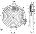
- the radiant heater 1 consists essentially of a bowl-shaped carrier 2, the bottom of which is arranged essentially parallel to the glass ceramic plate 3.
- the cup-shaped carrier 2 is made of metal.
- Insulation carrier 4 made of ceramic insulating materials is inserted into carrier 2 and is brought into a structured form, for example, by pouring, pressing and drying.
- An outer edge 5 is placed on the insulation support 4, which is formed in the example shown in FIG. 2 from a different material than the insulation support 4. However, the outer edge 5 can equally well be made in one piece with the insulation carrier 4.
- the spirally or helically arranged channels or tracks 6 for receiving the radiant heating resistor (s) 7.
- the glass ceramic plate 3 lies on the annular outer edge 5, which results in a free, closed space 8 between the radiant heating resistors 7 and the underside of the glass ceramic plate 3.
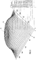
- the radiant heater 1 according to FIG. 1 there is, for example, a temperature distribution according to the diagram in FIG. 3. From this diagram it can be seen that the low temperatures of the glass ceramic plate 3 occur in the outer regions 20, while the entire middle region 9 has the high temperatures. The course of the curve in the diagram according to FIG. 3 also shows a remarkable temperature fluctuation in the middle area 9 for the person skilled in the art, which is essentially caused by the laying of the radiant heating resistors 7.
- the hottest point 10 on the underside of the glass ceramic plate 3 can be determined from the diagram in a mathematical and geometric relationship. According to the example in FIG. 3, the hottest point becomes 10 at the point shown, which is the highest point in the diagram and how it is then transferred to the radiant heater according to FIGS. 1 and 2.
- the temperature limiter 11 consists of a temperature sensor or sensor 12, which is located inside a tube 13.
- a quartz tube 13 which is guided radially from the outside to the hottest point 10, is provided, which is laid in the insulation support 4.
- the quartz tube 13 is bent at a right angle, as a result of which the front face 14 of the quartz tube 13, which is open at the top, is directed towards the hottest point 10.
- the temperature sensor 12 is located with its outer end at a short distance from the underside of the glass ceramic plate 3 and is exactly aligned with the hottest point 10.
- thermocouple temperature sensor 12
- the thermocouple 12 is located in a radial channel between the bottom of the carrier 2 and the insulation carrier 4. Below the hottest point 10, the thermocouple 12 is bent at right angles and runs in an upright ceramic tube 15, which is at a short distance ends below the glass ceramic plate 3.
- an inner sleeve 16 is also inserted into the ceramic tube 15 as the outer sleeve, within which the temperature sensor 12 runs until it abuts the underside of the glass ceramic plate 3.
- the inner sleeve 16 is under the action of a spring 17, whereby the inner sleeve is continuously pressed against the underside of the glass ceramic plate 3.
- the inner sleeve 16 is under the action of a so-called thermal bimetal spring 18, which ensures that the inner sleeve 16 is in the cold state of the radiant heater 1 or the glass ceramic plate 3 at an axial distance from the underside of the glass ceramic plate 3 .
- the inner sleeve 16 In the hot operating state of the glass ceramic plate 3, the inner sleeve 16 is pressed against the underside of the glass ceramic plate 3 by the bimetal spring 18.
- the outer end of the temperature sensor 12 is embedded in an insulating material 19 within the inner sleeve 16 and is in punctiform contact with the underside of the glass ceramic plate 3.
- the ceramic tube 15 or the inner sleeve 16 can be open with the end facing the glass ceramic plate 3.
- the front end can also be closed, as shown in FIG. 6.
- the seal can be made with an adhesive or other sealing compound. This has the advantage that oxidation and aging of the thermocouple 12 is prevented.
- the temperature sensor 12 contacts the underside of the glass ceramic plate 3 only under the influence of temperature.
- FIGS. 7 to 10 Further exemplary embodiments of a horizontal installation of the temperature sensor 12 are shown in the further FIGS. 7 to 10. It can be seen in FIG. 7 that the temperature sensor 12 is inserted in a jacket tube, which can be, for example, a quartz tube, a metal tube or a ceramic tube 13.
- the sensor head 20 of the temperature sensor 12 is covered by a cap 21 which can be placed on the outer tube 13, as a result of which heat and radiation insulation is produced.
- the sensor head 20 is located with the cover 21 in the hottest area 10, which is located between the plate 3 and the radiant heater 7 and is highlighted by dashed lines.
- the cover cap 21 which is completely closed according to FIG. 7, is provided with an opening 22 in the direction of the plate 3.
- the sensor head 20 of the temperature sensor 12 is reset behind a small front opening in the outer tube 3.
- the small end opening of the outer tube 13 in turn protrudes into the hottest area defined as the measuring zone.
- the outer tube 13 which extends into the measuring zone or the hottest area 10, with an internal temperature sensor 12 is bent at right angles to the glass ceramic plate 3 and is in direct contact with the underside of the glass ceramic plate 3.
- the sensor head 20 is located at a very small distance below the underside of the glass ceramic plate 3
- Outer tube 13 is again in the hottest area 10 as a so-called measuring zone.
- tracks could be applied directly to the underside of the glass ceramic plate as a temperature sensor, which are connected to a Pt element at a measuring station.
Landscapes
- Chemical & Material Sciences (AREA)
- Engineering & Computer Science (AREA)
- Ceramic Engineering (AREA)
- Resistance Heating (AREA)
- Electric Stoves And Ranges (AREA)
- Electric Ovens (AREA)
Applications Claiming Priority (2)
| Application Number | Priority Date | Filing Date | Title |
|---|---|---|---|
| DE19604306 | 1996-02-07 | ||
| DE19604306A DE19604306C2 (de) | 1996-02-07 | 1996-02-07 | Strahlungsheizkörper |
Publications (3)
| Publication Number | Publication Date |
|---|---|
| EP0789503A2 true EP0789503A2 (fr) | 1997-08-13 |
| EP0789503A3 EP0789503A3 (fr) | 1998-01-07 |
| EP0789503B1 EP0789503B1 (fr) | 2004-11-03 |
Family
ID=7784672
Family Applications (1)
| Application Number | Title | Priority Date | Filing Date |
|---|---|---|---|
| EP97101686A Expired - Lifetime EP0789503B1 (fr) | 1996-02-07 | 1997-02-04 | Corps de chauffe rayonnant |
Country Status (4)
| Country | Link |
|---|---|
| US (1) | US5877475A (fr) |
| EP (1) | EP0789503B1 (fr) |
| DE (2) | DE19604306C2 (fr) |
| ES (1) | ES2227630T3 (fr) |
Cited By (5)
| Publication number | Priority date | Publication date | Assignee | Title |
|---|---|---|---|---|
| EP2631545A1 (fr) * | 2012-02-22 | 2013-08-28 | Electrolux Home Products Corporation N.V. | Plaque de chauffage comprenant au moins un capteur de température |
| CN105559615A (zh) * | 2015-12-16 | 2016-05-11 | 阮保清 | 一种易装配的电饭锅限温器 |
| EP3771287A1 (fr) * | 2019-07-25 | 2021-01-27 | E.G.O. Elektro-Gerätebau GmbH | Dispositif chauffant à rayonnement et plaque de cuisson dotée d'un tel dispositif chauffant à rayonnement |
| WO2022144475A1 (fr) * | 2020-12-28 | 2022-07-07 | Eika, S.Coop. | Appareil de cuisson comprenant un foyer radiant |
| WO2023213616A1 (fr) * | 2022-05-03 | 2023-11-09 | E.G.O. Elektro-Gerätebau GmbH | Dispositif de chauffage par rayonnement et table de cuisson ayant un dispositif de chauffage par rayonnement |
Families Citing this family (20)
| Publication number | Priority date | Publication date | Assignee | Title |
|---|---|---|---|---|
| US6194689B1 (en) | 1998-05-11 | 2001-02-27 | Emerson Electric Co. | Radiant heater element for use in grill and the like |
| US6555793B2 (en) * | 1998-11-11 | 2003-04-29 | Emerson Electric Co. | Advanced radiant electric heater |
| US20040016746A1 (en) * | 1999-12-29 | 2004-01-29 | Ibiden Co., Ltd. | Ceramic heater |
| DE10006974A1 (de) * | 2000-02-16 | 2001-08-23 | Bsh Bosch Siemens Hausgeraete | Kochfeld mit Temperaturfühler |
| DE10006956A1 (de) * | 2000-02-16 | 2001-08-23 | Bsh Bosch Siemens Hausgeraete | Kochfeld mit Temperaturfühler |
| DE10006954A1 (de) * | 2000-02-16 | 2001-10-11 | Bsh Bosch Siemens Hausgeraete | Kochfeld mit Temperaturfühler |
| US6417496B1 (en) | 2000-12-22 | 2002-07-09 | Emerson Electric Co. | Modular heating unit for cooktops |
| US6403932B1 (en) | 2001-01-09 | 2002-06-11 | Emerson Electric Co. | Controller for a heating unit in a cooktop and methods of operating same |
| US6492627B1 (en) | 2001-07-26 | 2002-12-10 | Emerson Electric Co. | Heating unit and control system for cooktops having capability to detect presence of a pan and methods of operating same |
| GB0206069D0 (en) * | 2002-03-15 | 2002-04-24 | Ceramaspeed Ltd | Electrical heating assembly |
| JP2004200619A (ja) * | 2002-12-20 | 2004-07-15 | Kyocera Corp | ウエハ支持部材 |
| DE10356432A1 (de) * | 2003-11-28 | 2005-06-23 | E.G.O. Elektro-Gerätebau GmbH | Temperatursensor auf Basis von Widerstandsmessung und Strahlungsheizkörper mit einem solchen Temperatursensor |
| DE102005005520A1 (de) * | 2005-02-01 | 2006-08-10 | E.G.O. Elektro-Gerätebau GmbH | Heizeinrichtung mit Temperatursensor und Kochfeld mit Heizeinrichtungen |
| US20070251938A1 (en) * | 2006-04-26 | 2007-11-01 | Watlow Electric Manufacturing Company | Ceramic heater and method of securing a thermocouple thereto |
| KR100771628B1 (ko) * | 2006-05-11 | 2007-10-31 | 엘지전자 주식회사 | 전기레인지 |
| ES2341827B1 (es) * | 2008-05-23 | 2011-05-16 | Bsh Electrodomesticos España, S.A. | Campo de coccion con una placa de campo de coccion. |
| WO2010151839A1 (fr) * | 2009-06-26 | 2010-12-29 | Evo, Inc. | Appareil de cuisson électrique |
| JP6336205B2 (ja) * | 2015-10-12 | 2018-06-06 | コーニンクレッカ フィリップス エヌ ヴェKoninklijke Philips N.V. | 温度センサ付きブレンダ |
| CN105606256B (zh) * | 2016-02-16 | 2018-07-31 | 浙江绍兴苏泊尔生活电器有限公司 | 无线测温方法和锅具 |
| CN111902923A (zh) * | 2018-02-09 | 2020-11-06 | 应用材料公司 | 具有改进的温度控制的半导体处理设备 |
Citations (2)
| Publication number | Priority date | Publication date | Assignee | Title |
|---|---|---|---|---|
| DE3315657A1 (de) | 1983-04-29 | 1984-10-31 | E.G.O. Elektro-Geräte Blanc u. Fischer, 7519 Oberderdingen | Elektrokochgeraet |
| EP0141923B1 (fr) | 1983-09-17 | 1988-05-25 | E.G.O. Elektrogeräte AG | Limiteur de température pour plaques de cuisson en vitro-céramique |
Family Cites Families (14)
| Publication number | Priority date | Publication date | Assignee | Title |
|---|---|---|---|---|
| DE7315318U (de) * | 1973-07-12 | Imperial Werke Gmbh | Glaskeramik-Kochplatte | |
| US3622754A (en) * | 1970-07-24 | 1971-11-23 | Gen Electric | Glass plate surface heating unit with even temperature distribution |
| GB2138659B (en) * | 1980-01-14 | 1985-05-15 | Johnson Matthey Plc | Glass ceramic hob including temperature sensor |
| GB2071969B (en) * | 1980-03-05 | 1983-09-21 | Kenwood Mfg Co Ltd | Cooking apparatus |
| NZ197851A (en) * | 1980-08-13 | 1984-09-28 | Micropore International Ltd | Cooker element:temperature sensor receives heated air |
| JPS60256021A (ja) * | 1984-06-01 | 1985-12-17 | Matsushita Electric Ind Co Ltd | 温度センサ |
| DE3622415A1 (de) * | 1986-07-03 | 1988-01-07 | Ego Elektro Blanc & Fischer | Strahlheizkoerper |
| DE3705009A1 (de) * | 1987-02-17 | 1988-08-25 | Bosch Siemens Hausgeraete | Heizeinrichtung mit elektrisch beheizten strahlungsheizelementen |
| US4812624A (en) * | 1987-12-28 | 1989-03-14 | General Electric Company | Temperature sensor assembly for an automatic surface unit |
| JPH0464025A (ja) * | 1990-07-02 | 1992-02-28 | Matsushita Electric Ind Co Ltd | 調理器用温度センサー |
| DE4022845A1 (de) * | 1990-07-18 | 1992-01-23 | Schott Glaswerke | Temperatursensor oder -sensoranordnung aus glaskeramik und kontaktierenden filmwiderstaenden |
| DE4022846C2 (de) * | 1990-07-18 | 1994-08-11 | Schott Glaswerke | Vorrichtung zur Leistungssteuerung und -begrenzung bei einer Heizfläche aus Glaskeramik oder einem vergleichbaren Material |
| GB2263379B (en) * | 1992-01-10 | 1995-07-26 | Ceramaspeed Ltd | Radiant heater having multiple heating zones |
| DE4317040A1 (de) * | 1993-05-21 | 1994-04-28 | Schott Glaswerke | Glaskeramikkochfeld mit wenigstens einer Kochzone und einer zugeordneten Anzeigeeinrichtung |
-
1996
- 1996-02-07 DE DE19604306A patent/DE19604306C2/de not_active Expired - Fee Related
-
1997
- 1997-01-31 US US08/791,221 patent/US5877475A/en not_active Expired - Fee Related
- 1997-02-04 EP EP97101686A patent/EP0789503B1/fr not_active Expired - Lifetime
- 1997-02-04 DE DE59712046T patent/DE59712046D1/de not_active Expired - Fee Related
- 1997-02-04 ES ES97101686T patent/ES2227630T3/es not_active Expired - Lifetime
Patent Citations (2)
| Publication number | Priority date | Publication date | Assignee | Title |
|---|---|---|---|---|
| DE3315657A1 (de) | 1983-04-29 | 1984-10-31 | E.G.O. Elektro-Geräte Blanc u. Fischer, 7519 Oberderdingen | Elektrokochgeraet |
| EP0141923B1 (fr) | 1983-09-17 | 1988-05-25 | E.G.O. Elektrogeräte AG | Limiteur de température pour plaques de cuisson en vitro-céramique |
Cited By (5)
| Publication number | Priority date | Publication date | Assignee | Title |
|---|---|---|---|---|
| EP2631545A1 (fr) * | 2012-02-22 | 2013-08-28 | Electrolux Home Products Corporation N.V. | Plaque de chauffage comprenant au moins un capteur de température |
| CN105559615A (zh) * | 2015-12-16 | 2016-05-11 | 阮保清 | 一种易装配的电饭锅限温器 |
| EP3771287A1 (fr) * | 2019-07-25 | 2021-01-27 | E.G.O. Elektro-Gerätebau GmbH | Dispositif chauffant à rayonnement et plaque de cuisson dotée d'un tel dispositif chauffant à rayonnement |
| WO2022144475A1 (fr) * | 2020-12-28 | 2022-07-07 | Eika, S.Coop. | Appareil de cuisson comprenant un foyer radiant |
| WO2023213616A1 (fr) * | 2022-05-03 | 2023-11-09 | E.G.O. Elektro-Gerätebau GmbH | Dispositif de chauffage par rayonnement et table de cuisson ayant un dispositif de chauffage par rayonnement |
Also Published As
| Publication number | Publication date |
|---|---|
| DE19604306C2 (de) | 2000-05-11 |
| US5877475A (en) | 1999-03-02 |
| DE19604306A1 (de) | 1997-08-14 |
| ES2227630T3 (es) | 2005-04-01 |
| EP0789503B1 (fr) | 2004-11-03 |
| EP0789503A3 (fr) | 1998-01-07 |
| DE59712046D1 (de) | 2004-12-09 |
Similar Documents
| Publication | Publication Date | Title |
|---|---|---|
| EP0789503B1 (fr) | Corps de chauffe rayonnant | |
| EP0279368B1 (fr) | Limiteur de température | |
| DE10006956A1 (de) | Kochfeld mit Temperaturfühler | |
| EP1152639B2 (fr) | Unité de chauffage électrique, particulièrement destiné à des milieux liquides | |
| AT389612B (de) | Elektrische strahlungsheizeinheit | |
| DE3512236A1 (de) | Thermische sonde zum messen der temperatur eines in einem mikrowellenofen erwaermten gegenstands | |
| EP0116861B1 (fr) | Corps de chauffe radiant électrique pour le chauffage de plaques de cuisson ou de plaques chaudes, en particulier plaques en vitro-céramique | |
| EP0544244A2 (fr) | Dispositif pour détecter la température | |
| DE2500586A1 (de) | Elektrokochgeraet | |
| EP1258172B1 (fr) | Surface de cuisson avec capteur de temperature | |
| EP1844629B1 (fr) | Dispositif chauffant pourvu d'un capteur de temperature et plaque de cuisson comprenant des dispositifs chauffants | |
| EP0028356A1 (fr) | Indicateur de température pour la signalisation de l'état de température d'une surface de cuisson en verre-céramique | |
| EP1258170B1 (fr) | Ensemble plaque de cuisson dote d'un capteur de temperature | |
| EP1223597B1 (fr) | Limiteur de température | |
| EP0416335A1 (fr) | Interrupteur thermique | |
| DE19711541A1 (de) | Elektrokochplatte | |
| EP1452843B1 (fr) | Dispositif d'étalonnage et four | |
| EP1339260B1 (fr) | Capteur de température | |
| DE10006953A1 (de) | Kochfeld mit Temperaturfühler | |
| DE3315657A1 (de) | Elektrokochgeraet | |
| EP2131625B1 (fr) | Appareil de cuisson avec une plaque de cuisson avec un élément thermocouple | |
| DE10029244A1 (de) | Elektrische Heizvorrichtung | |
| DE3601634C2 (de) | Vorrichtung zum Regeln oder Begrenzen der Temperatur von Strahlungs- oder Kontaktheizkörpern | |
| WO2023213616A1 (fr) | Dispositif de chauffage par rayonnement et table de cuisson ayant un dispositif de chauffage par rayonnement | |
| EP3771287A1 (fr) | Dispositif chauffant à rayonnement et plaque de cuisson dotée d'un tel dispositif chauffant à rayonnement |
Legal Events
| Date | Code | Title | Description |
|---|---|---|---|
| PUAI | Public reference made under article 153(3) epc to a published international application that has entered the european phase |
Free format text: ORIGINAL CODE: 0009012 |
|
| AK | Designated contracting states |
Kind code of ref document: A2 Designated state(s): DE ES FR GB IT |
|
| PUAL | Search report despatched |
Free format text: ORIGINAL CODE: 0009013 |
|
| AK | Designated contracting states |
Kind code of ref document: A3 Designated state(s): DE ES FR GB IT |
|
| 17P | Request for examination filed |
Effective date: 19971217 |
|
| RAP1 | Party data changed (applicant data changed or rights of an application transferred) |
Owner name: DIEHL AKO STIFTUNG & CO. KG |
|
| RAP1 | Party data changed (applicant data changed or rights of an application transferred) |
Owner name: EIKA, S.COOP |
|
| 17Q | First examination report despatched |
Effective date: 20030814 |
|
| GRAP | Despatch of communication of intention to grant a patent |
Free format text: ORIGINAL CODE: EPIDOSNIGR1 |
|
| GRAS | Grant fee paid |
Free format text: ORIGINAL CODE: EPIDOSNIGR3 |
|
| GRAA | (expected) grant |
Free format text: ORIGINAL CODE: 0009210 |
|
| AK | Designated contracting states |
Kind code of ref document: B1 Designated state(s): DE ES FR GB IT |
|
| PG25 | Lapsed in a contracting state [announced via postgrant information from national office to epo] |
Ref country code: IT Free format text: LAPSE BECAUSE OF FAILURE TO SUBMIT A TRANSLATION OF THE DESCRIPTION OR TO PAY THE FEE WITHIN THE PRESCRIBED TIME-LIMIT;WARNING: LAPSES OF ITALIAN PATENTS WITH EFFECTIVE DATE BEFORE 2007 MAY HAVE OCCURRED AT ANY TIME BEFORE 2007. THE CORRECT EFFECTIVE DATE MAY BE DIFFERENT FROM THE ONE RECORDED. Effective date: 20041103 Ref country code: FR Free format text: LAPSE BECAUSE OF FAILURE TO SUBMIT A TRANSLATION OF THE DESCRIPTION OR TO PAY THE FEE WITHIN THE PRESCRIBED TIME-LIMIT Effective date: 20041103 |
|
| REG | Reference to a national code |
Ref country code: GB Ref legal event code: FG4D Free format text: NOT ENGLISH |
|
| REF | Corresponds to: |
Ref document number: 59712046 Country of ref document: DE Date of ref document: 20041209 Kind code of ref document: P |
|
| GBT | Gb: translation of ep patent filed (gb section 77(6)(a)/1977) |
Effective date: 20050208 |
|
| REG | Reference to a national code |
Ref country code: ES Ref legal event code: FG2A Ref document number: 2227630 Country of ref document: ES Kind code of ref document: T3 |
|
| PLBE | No opposition filed within time limit |
Free format text: ORIGINAL CODE: 0009261 |
|
| STAA | Information on the status of an ep patent application or granted ep patent |
Free format text: STATUS: NO OPPOSITION FILED WITHIN TIME LIMIT |
|
| 26N | No opposition filed |
Effective date: 20050804 |
|
| EN | Fr: translation not filed | ||
| PGFP | Annual fee paid to national office [announced via postgrant information from national office to epo] |
Ref country code: ES Payment date: 20080220 Year of fee payment: 12 |
|
| PGFP | Annual fee paid to national office [announced via postgrant information from national office to epo] |
Ref country code: GB Payment date: 20080220 Year of fee payment: 12 Ref country code: DE Payment date: 20080219 Year of fee payment: 12 |
|
| GBPC | Gb: european patent ceased through non-payment of renewal fee |
Effective date: 20090204 |
|
| PG25 | Lapsed in a contracting state [announced via postgrant information from national office to epo] |
Ref country code: DE Free format text: LAPSE BECAUSE OF NON-PAYMENT OF DUE FEES Effective date: 20090901 |
|
| REG | Reference to a national code |
Ref country code: ES Ref legal event code: FD2A Effective date: 20090205 |
|
| PG25 | Lapsed in a contracting state [announced via postgrant information from national office to epo] |
Ref country code: GB Free format text: LAPSE BECAUSE OF NON-PAYMENT OF DUE FEES Effective date: 20090204 |
|
| PG25 | Lapsed in a contracting state [announced via postgrant information from national office to epo] |
Ref country code: ES Free format text: LAPSE BECAUSE OF NON-PAYMENT OF DUE FEES Effective date: 20090205 |