EP0789503A2 - Radiant heater - Google Patents
Radiant heater Download PDFInfo
- Publication number
- EP0789503A2 EP0789503A2 EP97101686A EP97101686A EP0789503A2 EP 0789503 A2 EP0789503 A2 EP 0789503A2 EP 97101686 A EP97101686 A EP 97101686A EP 97101686 A EP97101686 A EP 97101686A EP 0789503 A2 EP0789503 A2 EP 0789503A2
- Authority
- EP
- European Patent Office
- Prior art keywords
- plate
- radiant heater
- temperature
- heater according
- temperature sensor
- Prior art date
- Legal status (The legal status is an assumption and is not a legal conclusion. Google has not performed a legal analysis and makes no representation as to the accuracy of the status listed.)
- Granted
Links
Images


Classifications
-
- H—ELECTRICITY
- H05—ELECTRIC TECHNIQUES NOT OTHERWISE PROVIDED FOR
- H05B—ELECTRIC HEATING; ELECTRIC LIGHT SOURCES NOT OTHERWISE PROVIDED FOR; CIRCUIT ARRANGEMENTS FOR ELECTRIC LIGHT SOURCES, IN GENERAL
- H05B3/00—Ohmic-resistance heating
- H05B3/68—Heating arrangements specially adapted for cooking plates or analogous hot-plates
- H05B3/74—Non-metallic plates, e.g. vitroceramic, ceramic or glassceramic hobs, also including power or control circuits
-
- H—ELECTRICITY
- H05—ELECTRIC TECHNIQUES NOT OTHERWISE PROVIDED FOR
- H05B—ELECTRIC HEATING; ELECTRIC LIGHT SOURCES NOT OTHERWISE PROVIDED FOR; CIRCUIT ARRANGEMENTS FOR ELECTRIC LIGHT SOURCES, IN GENERAL
- H05B2213/00—Aspects relating both to resistive heating and to induction heating, covered by H05B3/00 and H05B6/00
- H05B2213/07—Heating plates with temperature control means
Definitions
- the invention relates to a radiant heater according to the preamble of claim 1.
- Such radiant heaters generally have a support for an electrically operated heating system which consists of heating resistors.
- Such heating resistors are covered by a glass ceramic plate, stainless steel plate or similar plate or disc, which serves as a hotplate with its top. Due to their construction, such radiant heaters form, together with the glass ceramic plate, an essentially closed support space in which the radiant heating resistors are inserted. To avoid overheating of the glass ceramic plate, temperature limiters or temperature monitors are used in such radiant heaters.
- an electric cooking device with a glass ceramic plate which has a central opening with a sleeve inserted therein, in which a temperature sensor is arranged.
- the temperature sensor is held in the sleeve so as to be displaceable by spring force up to an upper stop, as a result of which the temperature sensor protrudes somewhat above the surface of the glass ceramic hotplate when it contacts the stop.
- thermosensor for a glass ceramic cooking unit
- the temperature sensor preferably runs approximately along a diameter over the hotplate or somewhat laterally offset to the hotplate.
- the temperature sensor itself consists of several partial rods, which are in a uniform, elongated Outer tube are housed. This configuration of the temperature sensor makes it possible to inform the temperature sensor of the different temperature influences resulting from the at least two heating surfaces in such a way that the response temperature of the temperature sensor is actually independent of whether one or two heating surfaces are in operation.
- temperature limiters are used which monitor the maximum value set on the underside of the glass ceramic plate and ensure that the maximum temperature of, for example, 600 ° C. or 700 ° C. on the underside of the glass ceramic plate is not exceeded.
- the temperature on the underside of the stainless steel or glass ceramic plate is not the same at all points, but essentially depends on the laying pattern of the heating conductor (s) and the dimensioning of the heating conductors. If a temperature distribution of the stainless steel or glass ceramic plate is now recorded in a diagram, so-called hot spots result which only rarely lie in the detection range of the sensor rod of the temperature limiter known per se.
- the temperature sensor or sensor of a temperature limiter is aligned precisely with the hottest point on the underside of the plate and thus optimally fulfills the task at hand.
- this orientation means that the hottest area to be detected can lie directly on the plate as a so-called measuring zone or between the plate made of stainless steel or glass ceramic and the radiant heater.
- the measuring zone does not necessarily have to be punctiform, but can also be provided between the radiant heater and the plate or cover with a diameter of approximately 15 mm, for example.
- the temperature is then usually recorded at points. This fulfills the function of a temperature monitor and enables usable cooking processes because a temperature limitation and a reaction to the temperature rise and the temperature drop is created.
- the heaters do not have the same temperature distribution, but rather have a very specific temperature profile
- the sensor was generally placed in the middle of the radiant heating system, because this is the best solution in terms of production technology with enough space applies.
- the evaluation electronics would have to assign the type of heating, power and temperature difference from the measurement point to the hottest point of the glass ceramic plate. This is technically very complex and complicated and also causes high costs. For this reason, the practice has been to indirectly carry out the temperature detection linearly via the heating center by means of an expansion rod.
- the temperature sensor for example a thermocouple
- This limit temperature is chosen so that the limit temperature of the glass ceramic plate under all operating conditions is observed.
- the limit temperature can advantageously be chosen so high that the usability of the entire system becomes, which leads, among other things, to shorter heating times.
- the direct temperature measurement eliminates the reduced limit temperature that is required for indirect measurement due to tolerances and the different heat distribution. Nevertheless, at least the same level of security is achieved.
- the sensor of the temperature limiter is brought as close as possible to the underside of the glass ceramic plate. An optimum is achieved when the sensor contacts the underside of the glass ceramic plate.
- the radiant heater 1 consists essentially of a bowl-shaped carrier 2, the bottom of which is arranged essentially parallel to the glass ceramic plate 3.
- the cup-shaped carrier 2 is made of metal.
- Insulation carrier 4 made of ceramic insulating materials is inserted into carrier 2 and is brought into a structured form, for example, by pouring, pressing and drying.
- An outer edge 5 is placed on the insulation support 4, which is formed in the example shown in FIG. 2 from a different material than the insulation support 4. However, the outer edge 5 can equally well be made in one piece with the insulation carrier 4.
- the spirally or helically arranged channels or tracks 6 for receiving the radiant heating resistor (s) 7.
- the glass ceramic plate 3 lies on the annular outer edge 5, which results in a free, closed space 8 between the radiant heating resistors 7 and the underside of the glass ceramic plate 3.
- the radiant heater 1 according to FIG. 1 there is, for example, a temperature distribution according to the diagram in FIG. 3. From this diagram it can be seen that the low temperatures of the glass ceramic plate 3 occur in the outer regions 20, while the entire middle region 9 has the high temperatures. The course of the curve in the diagram according to FIG. 3 also shows a remarkable temperature fluctuation in the middle area 9 for the person skilled in the art, which is essentially caused by the laying of the radiant heating resistors 7.
- the hottest point 10 on the underside of the glass ceramic plate 3 can be determined from the diagram in a mathematical and geometric relationship. According to the example in FIG. 3, the hottest point becomes 10 at the point shown, which is the highest point in the diagram and how it is then transferred to the radiant heater according to FIGS. 1 and 2.
- the temperature limiter 11 consists of a temperature sensor or sensor 12, which is located inside a tube 13.
- a quartz tube 13 which is guided radially from the outside to the hottest point 10, is provided, which is laid in the insulation support 4.
- the quartz tube 13 is bent at a right angle, as a result of which the front face 14 of the quartz tube 13, which is open at the top, is directed towards the hottest point 10.
- the temperature sensor 12 is located with its outer end at a short distance from the underside of the glass ceramic plate 3 and is exactly aligned with the hottest point 10.
- thermocouple temperature sensor 12
- the thermocouple 12 is located in a radial channel between the bottom of the carrier 2 and the insulation carrier 4. Below the hottest point 10, the thermocouple 12 is bent at right angles and runs in an upright ceramic tube 15, which is at a short distance ends below the glass ceramic plate 3.
- an inner sleeve 16 is also inserted into the ceramic tube 15 as the outer sleeve, within which the temperature sensor 12 runs until it abuts the underside of the glass ceramic plate 3.
- the inner sleeve 16 is under the action of a spring 17, whereby the inner sleeve is continuously pressed against the underside of the glass ceramic plate 3.
- the inner sleeve 16 is under the action of a so-called thermal bimetal spring 18, which ensures that the inner sleeve 16 is in the cold state of the radiant heater 1 or the glass ceramic plate 3 at an axial distance from the underside of the glass ceramic plate 3 .
- the inner sleeve 16 In the hot operating state of the glass ceramic plate 3, the inner sleeve 16 is pressed against the underside of the glass ceramic plate 3 by the bimetal spring 18.
- the outer end of the temperature sensor 12 is embedded in an insulating material 19 within the inner sleeve 16 and is in punctiform contact with the underside of the glass ceramic plate 3.
- the ceramic tube 15 or the inner sleeve 16 can be open with the end facing the glass ceramic plate 3.
- the front end can also be closed, as shown in FIG. 6.
- the seal can be made with an adhesive or other sealing compound. This has the advantage that oxidation and aging of the thermocouple 12 is prevented.
- the temperature sensor 12 contacts the underside of the glass ceramic plate 3 only under the influence of temperature.
- FIGS. 7 to 10 Further exemplary embodiments of a horizontal installation of the temperature sensor 12 are shown in the further FIGS. 7 to 10. It can be seen in FIG. 7 that the temperature sensor 12 is inserted in a jacket tube, which can be, for example, a quartz tube, a metal tube or a ceramic tube 13.
- the sensor head 20 of the temperature sensor 12 is covered by a cap 21 which can be placed on the outer tube 13, as a result of which heat and radiation insulation is produced.
- the sensor head 20 is located with the cover 21 in the hottest area 10, which is located between the plate 3 and the radiant heater 7 and is highlighted by dashed lines.
- the cover cap 21 which is completely closed according to FIG. 7, is provided with an opening 22 in the direction of the plate 3.
- the sensor head 20 of the temperature sensor 12 is reset behind a small front opening in the outer tube 3.
- the small end opening of the outer tube 13 in turn protrudes into the hottest area defined as the measuring zone.
- the outer tube 13 which extends into the measuring zone or the hottest area 10, with an internal temperature sensor 12 is bent at right angles to the glass ceramic plate 3 and is in direct contact with the underside of the glass ceramic plate 3.
- the sensor head 20 is located at a very small distance below the underside of the glass ceramic plate 3
- Outer tube 13 is again in the hottest area 10 as a so-called measuring zone.
- tracks could be applied directly to the underside of the glass ceramic plate as a temperature sensor, which are connected to a Pt element at a measuring station.
Landscapes
- Chemical & Material Sciences (AREA)
- Engineering & Computer Science (AREA)
- Ceramic Engineering (AREA)
- Resistance Heating (AREA)
- Electric Stoves And Ranges (AREA)
- Electric Ovens (AREA)
Abstract
Description
Die Erfindung betrifft einen Strahlungsheizkörper nach dem Oberbegriff des Patentanspruches 1.The invention relates to a radiant heater according to the preamble of
Solche Strahlungsheizkörper weisen im Regelfall einen Träger für eine elektrisch zu betreibende Beheizung auf die aus Heizwiderständen besteht. Solche Heizwiderstände werden durch eine Glaskeramikplatte, Edelstahlplatte oder dergleichen Platte oder Scheibe abgedeckt, welche mit ihrer Oberseite als Kochplatte dient. Durch ihren Aufbau bilden solche Strahlungsheizkörper zusammen mit der Glaskeramikplatte einen nach außen im wesentlichen geschlossenen Trägerraum, in welchem die Strahlheizwiderstände eingesetzt sind. Um eine Überhitzung der Glaskeramikplatte zu vermeiden, werden bei solchen Strahlungsheizkörpern Temperaturbegrenzer bzw. Temperaturwächter eingesetzt.Such radiant heaters generally have a support for an electrically operated heating system which consists of heating resistors. Such heating resistors are covered by a glass ceramic plate, stainless steel plate or similar plate or disc, which serves as a hotplate with its top. Due to their construction, such radiant heaters form, together with the glass ceramic plate, an essentially closed support space in which the radiant heating resistors are inserted. To avoid overheating of the glass ceramic plate, temperature limiters or temperature monitors are used in such radiant heaters.
Durch die DE 33 15 657 A1 ist ein Elektrokochgerät mit einer Glaskeramikplatte bekannt, welche eine zentrale Öffnung mit einer darin eingesetzten Hülse aufweist, in welcher ein Temperaturfühler angeordnet ist. Dabei ist der Temperaturfühler in der Hülse bis gegen einen oberen Anschlag durch Federkraft verschiebbar gehalten, wodurch der Temperaturfühler beim Anliegen an dem Anschlag etwas über der Oberfläche der Glaskeramikkochplatte übersteht.From DE 33 15 657 A1 an electric cooking device with a glass ceramic plate is known which has a central opening with a sleeve inserted therein, in which a temperature sensor is arranged. The temperature sensor is held in the sleeve so as to be displaceable by spring force up to an upper stop, as a result of which the temperature sensor protrudes somewhat above the surface of the glass ceramic hotplate when it contacts the stop.
Eine andere Bauanordnung und Bauart eines Temperaturbegrenzers für eine Glaskeramikkocheinheit ist durch die EP 0 141 923 B1 bekannt. In diesem Fall verläuft der Temperaturfühler vorzugsweise etwa längs eines Durchmessers über die Kochstelle oder aber etwas seitlich versetzt zur Kochstelle. Der Temperaturfühler selbst besteht aus mehreren Teilstäben, die in einem einheitlichen, langgestreckten Außenrohr untergebracht sind. Durch diese Ausgestaltung des Temperaturfühlers wird es möglich, die aus den mindestens zwei Heizflächen resultierenden, unterschiedlichen Temperatureinflüsse dem Temperaturfühler so mitzuteilen, daß die Ansprechtemperatur des Temperaturfühlers tatsächlich unabhängig davon ist, ob eine oder zwei Heizflächen in Betrieb sind.Another construction arrangement and construction of a temperature limiter for a glass ceramic cooking unit is known from
Bei Strahlungsheizkörpern bzw. Strahlungsbeheizungen ist es grundsätzlich wichtig und durch Sicherheitsvorschriften auch vorgeschrieben, daß die Temperatur an der Unterseite der Glaskeramikplatte einen Maximalwert nicht überschreitet, um eine Schädigung der Glaskeramikplatte zu vermeiden. Aus diesem Grunde werden Temperaturbegrenzer eingesetzt, die den eingestellten Maximalwert an der Unterseite der Glaskeramikplatte überwachen und gewährleisten, daß die maximale Temperatur von beispielsweise 600°C oder 700 °C an der Unterseite der Glaskeramikplatte nicht überschritten wird.In the case of radiant heaters or radiant heaters, it is fundamentally important and also prescribed by safety regulations that the temperature on the underside of the glass ceramic plate does not exceed a maximum value in order to avoid damage to the glass ceramic plate. For this reason, temperature limiters are used which monitor the maximum value set on the underside of the glass ceramic plate and ensure that the maximum temperature of, for example, 600 ° C. or 700 ° C. on the underside of the glass ceramic plate is not exceeded.
Es ist nun aber bekannt, daß die Temperatur an der Unterseite der Edelstahl- oder Glaskeramikplatte nicht an allen Punkten gleich ist, sondern im wesentlichen von dem Verlegungsbild des bzw. der Heizleiter und der Dimensionierung der Heizleiter abhängt. Wird nun eine Temperaturverteilung der Edelstahl- oder Glaskeramikplatte in einem Diagramm aufgezeichnet, so ergeben sich sogenannte Heißpunkte, die nur selten im Erfassungsbereich des an sich bekannten Fühlerstabes des Temperaturbegrenzers liegen.It is now known, however, that the temperature on the underside of the stainless steel or glass ceramic plate is not the same at all points, but essentially depends on the laying pattern of the heating conductor (s) and the dimensioning of the heating conductors. If a temperature distribution of the stainless steel or glass ceramic plate is now recorded in a diagram, so-called hot spots result which only rarely lie in the detection range of the sensor rod of the temperature limiter known per se.
Es ist Aufgabe der Erfindung, einen Strahlungsheizkörper der eingangs genannten Art zu schaffen, bei dem ein Temperaturfühler eines Temperaturbegrenzers punktweise oder nahezu punktweise die Temperatur Edelstahl- oder der Glaskeramikplatte erfaßt und beispielsweise in Form von elektrischen Spannungsdifferenzen an die Regeleinrichtung des Strahlungsheizkörpers weitergibt.It is an object of the invention to provide a radiant heater of the type mentioned, in which a temperature sensor of a temperature limiter detects the temperature of the stainless steel or the glass ceramic plate at points or almost at points and for example in the form of electrical voltage differences to the control device of the radiant heater.
Erfindungsgemäß wird diese Aufgabe durch die Merkmale des Patentanspruches 1 gelöst. Erfinderische Ausgestaltungen und Weiterbildungen sind in den Unteransprüchen 2 bis 12 genannt.According to the invention, this object is achieved by the features of
Der besondere Vorteil der Erfindung wird darin gesehen, daß der Temperaturfühler bzw. Sensor eines Temperaturbegrenzers genau auf den heißesten Punkt der Plattenunterseite ausgerichtet ist und damit die gestellte Aufgabe optimal erfüllt. Unter dieser Ausrichtung wird im Sinne der Erfindung verstanden, daß der zu erfassende heißeste Bereich als sogenannte Meßzone direkt auf der Platte oder auch zwischen der Platte aus Edelstahl oder Glaskeramik und der Strahlungsheizung liegen kann. Die Meßzone muß nicht zwangsläufig nur punktförmig sein, sondern kann auch zwischen der Strahlungsheizung und der Platte bzw. Abdeckung im Durchmesser von beispielsweise etwa 15 mm vorgesehen sein. Die Erfassung der Temperatur erfolgt dann im Regelfall punktförmig. Dadurch wird die Funktion eines Temperaturwächters erfüllt und es werden gebrauchstaugliche Kochvorgänge möglich, weil eine Temperaturbegrenzung und eine Reaktion auf den Temperaturanstieg sowie aufden Temperaturabfall geschaffen wird.The particular advantage of the invention is seen in the fact that the temperature sensor or sensor of a temperature limiter is aligned precisely with the hottest point on the underside of the plate and thus optimally fulfills the task at hand. In the sense of the invention, this orientation means that the hottest area to be detected can lie directly on the plate as a so-called measuring zone or between the plate made of stainless steel or glass ceramic and the radiant heater. The measuring zone does not necessarily have to be punctiform, but can also be provided between the radiant heater and the plate or cover with a diameter of approximately 15 mm, for example. The temperature is then usually recorded at points. This fulfills the function of a temperature monitor and enables usable cooking processes because a temperature limitation and a reaction to the temperature rise and the temperature drop is created.
Obwohl das Problem an sich bekannt ist, daß die Beheizungen keine gleiche Temperaturverteilung aufweisen, sondern eine ganz bestimmtes Temperaturprofil aufweisen, wurde bei den bekannten Temperaturbegrenzern der Sensor im Regelfall in die Mitte der Strahlungsbeheizung gesetzt, weil dies als die produktionstechnisch beste Lösung mit ausreichend viel Platz gilt. Um bei dieser Lösung zu einem gesicherten Meßergebnis für die Temperatur zu kommen, müßte in der Auswerteelektronik eine Zuordnung von Heizungstyp, Leistung und Temperaturdifferenz vom Meßpunkt zum heißesten Punkt der Glaskeramikplatte erfolgen. Dies ist technisch sehr aufwendig und kompliziert und verursacht außerdem hohe Kosten. Deshalb ist man in der Praxis dazu hergegangen, die Temperaturerfassung linear über die Beheizungsmitte durch einen Ausdehnungsstab indirekt zu vollziehen.Although the problem is known per se that the heaters do not have the same temperature distribution, but rather have a very specific temperature profile, in the known temperature limiters the sensor was generally placed in the middle of the radiant heating system, because this is the best solution in terms of production technology with enough space applies. In order to achieve a reliable measurement result for the temperature with this solution, the evaluation electronics would have to assign the type of heating, power and temperature difference from the measurement point to the hottest point of the glass ceramic plate. This is technically very complex and complicated and also causes high costs. For this reason, the practice has been to indirectly carry out the temperature detection linearly via the heating center by means of an expansion rod.
Gerade diese Nachteile werden durch die Merkmale der Erfindung vermieden, weil nun der Temperaturfühler, beispielsweise ein Thermoelement, bei jeder Bauart eines Strahlungsheizkörpers an den typspezifischen, heißesten Punkt gesetzt wird. Dies bedeutet eine direkte Temperaturmessung. Damit braucht unabhängig von der Beheizungsvarianten-Vielfalt in der Signalverarbeitung nur eine Grenztemperatur in Form von Spannung festgelegt zu werden. Diese Grenztemperatur wird so gewählt, daß die Grenztemperatur der Glaskeramikplatte unter allen Betriebsbedingungen eingehalten wird. Die Grenztemperatur kann vorteilhafterweise dennoch so hoch gewählt werden, daß die Gebrauchstauglichkeit des gesamten Systems wird, was u.a. zu kürzeren Ankochzeiten führt. Durch die direkte Temperaturmessung entfällt die reduzierte Grenztemperatur, die bei der indirekten Messung aufgrund von Toleranzen und der unterschiedlichen Wärmeverteilung erforderlich ist. Trotzdem wird mindestens die gleiche Sicherheit erzielt. Der Sensor des Temperaturbegrenzers wird möglichst nahe an die Unterseite der Glaskeramikplatte herangeführt. Ein Optimum wird dann erreicht, wenn der Sensor die Unterseite der Glaskeramikplatte kontaktiert.Precisely these disadvantages are avoided by the features of the invention, because now the temperature sensor, for example a thermocouple, is placed at the type-specific, hottest point in every type of radiant heater. This means a direct temperature measurement. Regardless of the variety of heating variants in signal processing, only a limit temperature in the form of voltage needs to be defined. This limit temperature is chosen so that the limit temperature of the glass ceramic plate under all operating conditions is observed. The limit temperature can advantageously be chosen so high that the usability of the entire system becomes, which leads, among other things, to shorter heating times. The direct temperature measurement eliminates the reduced limit temperature that is required for indirect measurement due to tolerances and the different heat distribution. Nevertheless, at least the same level of security is achieved. The sensor of the temperature limiter is brought as close as possible to the underside of the glass ceramic plate. An optimum is achieved when the sensor contacts the underside of the glass ceramic plate.
In der Zeichnung ist ein Beispiel der Erfindung dargestellt. Darin zeigen:
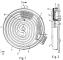
Figur 1- die Draufsicht auf einen Strahlungsheizkörper,
Figur 2- einen Teilschnitt durch den Strahlungsheizkörper gemäß der Linie II-II in
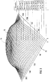
Figur 1, Figur 3- die Temperaturverteilungskurve eines Strahlungsheizkörpers nach
Figur 1, - Figur 4
- die Teilansicht des Strahlungsheizkörpers gemäß der Linie II-II in
Figur 1 mit anderem Thermoelement, Figur 5- die Schnittdarstellung des Thermoelementes,
Figur 6- die Schnittdarstellung des Thermoelementes in anderer Ausführung,
Figur 7- einen Teilschnitt durch einen Strahlungsheizkörper anderer Bauart,
Figur 8- einen Teilschnitt durch einen Strahlungsheizkörper noch anderer Bauart,
- Figur 9
- einen Teilschnitt durch einen Strahlungsheizkörper noch anderer Bauart,
Figur 10- einen Teilschnitt durch einen Strahlungsheizkörper noch anderer Bauart.
- Figure 1
- the top view of a radiant heater,
- Figure 2
- 2 shows a partial section through the radiant heater according to line II-II in FIG. 1,
- Figure 3
- the temperature distribution curve of a radiant heater according to Figure 1,
- Figure 4
- 1 is a partial view of the radiant heater according to line II-II in FIG. 1 with a different thermocouple,
- Figure 5
- the sectional view of the thermocouple,
- Figure 6
- the sectional view of the thermocouple in another version,
- Figure 7
- a partial section through a radiant heater of another type,
- Figure 8
- a partial section through a radiant heater of yet another type,
- Figure 9
- a partial section through a radiant heater of yet another type,
- Figure 10
- a partial section through a radiant heater of yet another type.
Der Strahlungsheizkörper 1 besteht im wesentlichen aus einem schalenförmigen Träger 2, dessen Boden im wesentlichen parallel zur Glaskeramikplatte 3 angeordnet ist. Der schalenförmige Träger 2 ist aus Metall gefertigt. In den Träger 2 ist der Isolationsträger 4 aus keramischen Isolierwerkstoffen eingesetzt, die beispielsweise durch Schüttung, Verpressung und Trocknung in eine strukturierte Form gebracht werden. Auf den Isolationsträger 4 ist ein Außenrand 5 aufgesetzt, der in dem gezeigten Beispiel nach Figur 2 aus einem zu dem Isolationsträger 4 unterschiedlichen Werkstoff gebildet ist. Der Außenrand 5 kann jedoch ebensogut auch einteilig mit dem Isolationsträger 4 hergestellt sein. In die der Glaskeramikplatte zugewendeten Oberseite des Isolationsträgers 4 befinden sich die spiralförmig oder wendelförmig angeordneten Rinnen oder Bahnen 6 für die Aufnahme des oder der Strahlheizwiderstände 7.The
Die Glaskeramikplatte 3 liegt auf dem ringförmigen Außenrand 5 auf, wodurch sich zwischen den Strahlheizwiderständen 7 und der Unterseite der Glaskeramikplatte 3 ein freier, geschlossener Raum 8 ergibt.The glass
Für den Strahlungsheizkörper 1 nach Figur 1 ergibt sich nun beispielsweise eine Temperaturverteilung nach dem Diagramm in Figur 3. Aus diesem Diagramm ist erkennbar, daß die niedrigen Temperaturen der Glaskeramikplatte 3 in den Außenbereichen 20 auftreten, während der gesamte mittlere Bereich 9 die hohen Temperaturen aufweist. Durch den Kurvenverlauf im Diagramm nach Figur 3 zeigt sich für den Fachmann aber auch in dem mittleren Bereich 9 noch eine bemerkenswerte Temperaturschwankung, die im wesentlichen durch die Verlegung der Strahlheizwiderstände 7 verursacht wird. Aus dem Diagramm ist in mathematischer und geometrischer Beziehung der heißeste Punkt 10 auf der Unterseite der Glaskeramikplatte 3 zu ermitteln. Nach dem Beispiel in Figur 3 wird der heißeste Punkt 10 an der eingezeichneten Stelle angenommen, welche im Diagramm der höchste Punkt ist und wie er dann auf den Strahlungsheizkörper nach den Figur 1 und 2 übertragen ist.For the
Der Temperaturbegrenzer 11 besteht aus einem Temperaturfühler oder Sensor 12, der sich im Inneren eines Röhrchens 13 befindet. Nach Figur 2 ist ein radial von außen zum heißesten Punkt 10 geführtes Quarzrohr 13 vorgesehen, welches in dem Isolationsträger 4 verlegt ist. Unterhalb des heißesten Punktes auf der Unterseite der Glaskeramikplatte 3 ist das Quarzrohr 13 im rechten Winkel abgebogen, wodurch die oben offene Stirnseite 14 des Quarzrohres 13 auf den heißesten Punkt 10 gerichtet ist. Der Temperaturfühler 12 befindet sich mit seinem äußeren Ende in einem geringen Abstand zur Unterseite der Glaskeramikplatte 3 und ist exakt auf den heißesten Punkt 10 ausgerichtet.The temperature limiter 11 consists of a temperature sensor or
In Figur 4 befindet sich das Thermoelement (Temperaturfühler 12) in einem radialen Kanal zwischen dem Boden des Trägers 2 und dem Isolationsträger 4. Unterhalb des heißesten Punktes 10 ist das Thermoelement 12 rechtwinklig abgebogen und verläuft in einem aufrechtstehenden Keramikröhrchen 15, welches mit einem geringen Abstand unterhalb der Glaskeramikplatte 3 endet.In Figure 4, the thermocouple (temperature sensor 12) is located in a radial channel between the bottom of the
Wie Figur 5 zeigt, ist in das Keramikröhrchen 15 als Außenhülse noch eine Innenhülse 16 eingesetzt, innerhalb der der Temperaturfühler 12 bis in Anlage an die Unterseite der Glaskeramikplatte 3 verläuft. Die Innenhülse 16 steht unter der Wirkung einer Feder 17, wodurch die Innenhülse kontinuierlich an die Unterseite der Glaskeramikplatte 3 gedrückt wird. Nach Figur 6 befindet sich die Innenhülse 16 unter der Wirkung einer sogenannten Thermo-Bimetall-Feder 18, wodurch erreicht wird, daß sich die Innenhülse 16 im kalten Zustand des Strahlungsheizkörpers 1 bzw. der Glaskeramikplatte 3 in einem axialen Abstand zur Unterseite der Glaskeramikplatte 3 befindet. In dem heißen Betriebszustand der Glaskeramikplatte 3 wird die Innenhülse 16 durch die Bimetallfeder 18 gegen die Unterseite der Glaskeramikplatte 3 gedrückt. Der Temperaturfühler 12 ist mit seinem äußeren Ende in ein Isoliermaterial 19 innerhalb der Innenhülse 16 eingebettet und liegt punktförmig an der Unterseite der Glaskeramikplatte 3 an.As FIG. 5 shows, an
Wie die vorgenannten Beispiele zeigen, kann das Keramikrohr 15 bzw. die Innenhülse 16 mit dem zur Glaskeramikplatte 3 zugewandten Stirnende offen sein. Das Stirnende kann auch verschlossen sein, wie dies in Figur 6 gezeigt ist. Alternativ kann der Verschluß durch eine Klebe- oder andere Dichtungsmasse erfolgen. Dies hat den Vorteil, daß eine Oxydation und Alterung des Thermoelementes 12 verhindert wird. In dem Beispiel nach Figur 6 kontaktiert der Temperaturfühler 12 die Unterseite der Glaskeramikplatte 3 nur unter Temperatureinfluß.As the above examples show, the
In den weiteren Figuren 7 bis 10 sind weitere Ausführungsbeispiele eines waagerechten Einbaus des Temperaturfühlers 12 dargestellt. So ist in Figur 7 zu erkennen, daß der Temperaturfühler 12 in einem Mantelrohr, welches beispielsweise ein Quarzrohr, ein Metallrohr oder ein Keramikrohr 13 sein kann, eingeführt ist. Der Sensorkopf 20 des Temperaturfühlers 12 ist durch eine auf das Außenrohr 13 aufsetzbare Kappe 21 abgedeckt, wodurch eine Wärme- und Strahlungsisolierung hervorgerufen wird. Der Sensorkopf 20 befindet sich mit der Abdeckhaube 21 in dem heißesten Bereich 10, der sich zwischen der Platte 3 und der Strahlungsheizung 7 befindet und durch gestrichelte Linien hervorgehoben ist.Further exemplary embodiments of a horizontal installation of the
In Figur 8 ist die nach Figur 7 rundum geschlossene Abdeckkappe 21 mit einer Öffnung 22 in Richtung zur Platte 3 versehen.In FIG. 8, the
Entsprechend der Darstellung in Figur 9 ist der Sensorkopf 20 des Temperaturfühlers 12 hinter einer kleinen stirnseitigen Öffnung des Außenrohres 3 zurückgesetzt. Die kleine stirnseitige Öffnung des Außenrohres 13 ragt wiederum in den als Meßzone deffinierten heißesten Bereich ein.According to the illustration in FIG. 9, the
In Figur 10 ist das bis in die Meßzone bzw. den heißesten Bereich 10 geführte Außenrohr 13 mit innenliegendem Temperaturfühler 12 im rechten Winkel zur Glaskeramikplatte 3 abgebogen und steht mit seiner offenen Stirnseite direkt an der Unterseite der Glaskeramikplatte 3 an. Der Sensorkopf 20 liegt in einem sehr kleinen Abstand unterhalb der Unterseite der Glaskeramikplatte 3. Die Abbiegung des Außenrohres 13 befindet sich wiederum in dem heißesten Bereich 10 als sogenannte Meßzone.In FIG. 10, the
Im Sinne der Erfindung sind natürlich auch weitere Ausführungsbeispiele denkbar, so könnten beispielsweise auf der Unterseite der Glaskeramikplatte direkt Bahnen als Temperatursensor aufgebracht sein, die an einem Meßplatz mit einem Pt-Element verbunden sind.In the sense of the invention, further exemplary embodiments are of course also conceivable, for example, tracks could be applied directly to the underside of the glass ceramic plate as a temperature sensor, which are connected to a Pt element at a measuring station.
Claims (12)
dadurch gekennzeichnet,
daß der Temperaturbegrenzer (11) einen Temperaturfühler (12) aufweist, der zur direkten Temperaturerfassung auf den heißesten Bereich (10) der Platte (3) bzw. zwischen der Platte (3) und der Strahlheizung ausgerichtet ist.Radiant heater (1) with a support (2) for at least one radiant heating resistor (7), with a plate (3), disc or the like covering the radiant heating resistor (7) and a temperature limiter or temperature monitor (11),
characterized,
that the temperature limiter (11) has a temperature sensor (12) which is aligned for direct temperature detection on the hottest area (10) of the plate (3) or between the plate (3) and the radiant heater.
dadurch gekennzeichnet,
daß der heißeste Bereich eine kleine bis punktförmige Flächenausdehnung hat.Radiant heater according to claim 1,
characterized,
that the hottest area has a small to punctiform area.
dadurch gekennzeichnet,
daß der Temperaturfühler (12) im heißesten Bereich (10) die Unterseite der Platte (3) berührt oder nahezu berührt.Radiant heater according to claim 1 or 2,
characterized,
that the temperature sensor (12) in the hottest area (10) touches or almost touches the underside of the plate (3).
dadurch gekennzeichnet,
daß der Temperaturfühler (12) elektrisch isoliert ummantelt ist, wobei das stirnseitige Ende wahlweise zur Platte (3) hin geöffnet ist.Radiant heater according to claim 1 or 3,
characterized,
that the temperature sensor (12) is sheathed in an electrically insulated manner, the front end optionally being open towards the plate (3).
dadurch gekennzeichnet,
daß der Temperaturfühler (12) wärmeisoliert ummantelt ist.Radiant heater according to one of claims 1 to 4,
characterized,
that the temperature sensor (12) is covered with heat insulation.
dadurch gekennzeichnet,
daß der Temperaturfühler (12) in eine Hülse, Rohr oder dergleichen (15) eingesetzt ist.Radiant heater according to claim 5,
characterized,
that the temperature sensor (12) is inserted into a sleeve, tube or the like (15).
dadurch gekennzeichnet,
daß die Hülse (15) durch eine Feder (17) beaufschlagt ist und stirnseitig an der Unterseite der Platte (3) anliegt.Radiant heater according to claim 6,
characterized,
that the sleeve (15) is acted upon by a spring (17) and rests on the end face on the underside of the plate (3).
dadurch gekennzeichnet,
daß die Hülse (15) durch eine thermisch reagierende Bimetall-Feder (18) beaufschlagt ist und im heißen Zustand an der Unterseite der Platte (3) anliegt.Radiant heater according to claim 6,
characterized,
that the sleeve (15) is acted upon by a thermally reactive bimetallic spring (18) and, when hot, bears against the underside of the plate (3).
dadurch gekennzeichnet,
daß die Hülse (15) an ihrem der Glaskeramikplatte (3) zugewandten Stirnende (14) geschlossen ist.Radiant heater according to claim 6, 7 or 8,
characterized,
that the sleeve (15) is closed at its end (14) facing the glass ceramic plate (3).
dadurch gekennzeichnet,
daß das der Platte (3) zugewandten Stirnende (14) der Hülse (15) mit der Platte (3) verklebt ist.Radiant heater according to one of claims 6 to 9,
characterized,
that the end (14) of the sleeve (15) facing the plate (3) is glued to the plate (3).
dadurch gekennzeichnet,
daß die Hülse (15) ein Quarzrohr, ein Keramikrohr oder dergleichen Werkstoff ist.Radiant heater according to one of claims 6 to 10,
characterized,
that the sleeve (15) is a quartz tube, a ceramic tube or the like material.
dadurch gekennzeichnet,
daß die Platte (3) aus Keramik, Edelstahl oder dergleichen geeigneten Werk stoff gebildet ist.Radiant heater according to one of the preceding claims,
characterized,
that the plate (3) made of ceramic, stainless steel or the like suitable material.
Applications Claiming Priority (2)
| Application Number | Priority Date | Filing Date | Title |
|---|---|---|---|
| DE19604306A DE19604306C2 (en) | 1996-02-07 | 1996-02-07 | Radiant heater |
| DE19604306 | 1996-02-07 |
Publications (3)
| Publication Number | Publication Date |
|---|---|
| EP0789503A2 true EP0789503A2 (en) | 1997-08-13 |
| EP0789503A3 EP0789503A3 (en) | 1998-01-07 |
| EP0789503B1 EP0789503B1 (en) | 2004-11-03 |
Family
ID=7784672
Family Applications (1)
| Application Number | Title | Priority Date | Filing Date |
|---|---|---|---|
| EP97101686A Expired - Lifetime EP0789503B1 (en) | 1996-02-07 | 1997-02-04 | Radiant heater |
Country Status (4)
| Country | Link |
|---|---|
| US (1) | US5877475A (en) |
| EP (1) | EP0789503B1 (en) |
| DE (2) | DE19604306C2 (en) |
| ES (1) | ES2227630T3 (en) |
Cited By (5)
| Publication number | Priority date | Publication date | Assignee | Title |
|---|---|---|---|---|
| EP2631545A1 (en) * | 2012-02-22 | 2013-08-28 | Electrolux Home Products Corporation N.V. | A heating plate including at least one temperature sensor element |
| CN105559615A (en) * | 2015-12-16 | 2016-05-11 | 阮保清 | Easily assembled electric cooker temperature limiter |
| EP3771287A1 (en) * | 2019-07-25 | 2021-01-27 | E.G.O. Elektro-Gerätebau GmbH | Radiation heating device and hob with such a radiation heating device |
| WO2022144475A1 (en) * | 2020-12-28 | 2022-07-07 | Eika, S.Coop. | Cooking appliance comprising a radiant burner |
| WO2023213616A1 (en) * | 2022-05-03 | 2023-11-09 | E.G.O. Elektro-Gerätebau GmbH | Radiant heater and cooktop having a radiant heater |
Families Citing this family (20)
| Publication number | Priority date | Publication date | Assignee | Title |
|---|---|---|---|---|
| US6194689B1 (en) | 1998-05-11 | 2001-02-27 | Emerson Electric Co. | Radiant heater element for use in grill and the like |
| US6555793B2 (en) * | 1998-11-11 | 2003-04-29 | Emerson Electric Co. | Advanced radiant electric heater |
| US20040016746A1 (en) * | 1999-12-29 | 2004-01-29 | Ibiden Co., Ltd. | Ceramic heater |
| DE10006974A1 (en) * | 2000-02-16 | 2001-08-23 | Bsh Bosch Siemens Hausgeraete | Cooker hob zone has temperature sensor attached to heat conducting element within heating element and in thermally conducting contact with underside of cooking plate |
| DE10006954A1 (en) * | 2000-02-16 | 2001-10-11 | Bsh Bosch Siemens Hausgeraete | Ceramic cooking hob has temperature sensor supported by fixing element extending from point on outside of heating element in contact with underside of hob surface on inside of heating element |
| DE10006956A1 (en) * | 2000-02-16 | 2001-08-23 | Bsh Bosch Siemens Hausgeraete | Cooker hob zone has temperature sensor in thermal contact with underside of hob plate via heat conducting element and screened against thermal radiation from heater by insulating material |
| US6417496B1 (en) | 2000-12-22 | 2002-07-09 | Emerson Electric Co. | Modular heating unit for cooktops |
| US6403932B1 (en) | 2001-01-09 | 2002-06-11 | Emerson Electric Co. | Controller for a heating unit in a cooktop and methods of operating same |
| US6492627B1 (en) | 2001-07-26 | 2002-12-10 | Emerson Electric Co. | Heating unit and control system for cooktops having capability to detect presence of a pan and methods of operating same |
| GB0206069D0 (en) * | 2002-03-15 | 2002-04-24 | Ceramaspeed Ltd | Electrical heating assembly |
| JP2004200619A (en) * | 2002-12-20 | 2004-07-15 | Kyocera Corp | Wafer supporting member |
| DE10356432A1 (en) * | 2003-11-28 | 2005-06-23 | E.G.O. Elektro-Gerätebau GmbH | Temperature sensor based on resistance measurement and radiant heater with such a temperature sensor |
| DE102005005520A1 (en) | 2005-02-01 | 2006-08-10 | E.G.O. Elektro-Gerätebau GmbH | Heating device with temperature sensor and hob with heaters |
| US20070251938A1 (en) * | 2006-04-26 | 2007-11-01 | Watlow Electric Manufacturing Company | Ceramic heater and method of securing a thermocouple thereto |
| KR100771628B1 (en) * | 2006-05-11 | 2007-10-31 | 엘지전자 주식회사 | Electricity oven |
| ES2341827B1 (en) * | 2008-05-23 | 2011-05-16 | Bsh Electrodomesticos España, S.A. | COOKING FIELD WITH A COOKING FIELD PLATE. |
| WO2010151839A1 (en) * | 2009-06-26 | 2010-12-29 | Evo, Inc. | Electric cooking apparatus |
| EP3220789B1 (en) * | 2015-10-12 | 2018-06-06 | Koninklijke Philips N.V. | A blender with temperature sensor |
| CN105606256B (en) * | 2016-02-16 | 2018-07-31 | 浙江绍兴苏泊尔生活电器有限公司 | Wireless temperature measurement method and cooker |
| SG11202007857XA (en) * | 2018-02-09 | 2020-09-29 | Applied Materials Inc | Semiconductor processing apparatus having improved temperature control |
Citations (2)
| Publication number | Priority date | Publication date | Assignee | Title |
|---|---|---|---|---|
| DE3315657A1 (en) | 1983-04-29 | 1984-10-31 | E.G.O. Elektro-Geräte Blanc u. Fischer, 7519 Oberderdingen | Electric cooking appliance |
| EP0141923B1 (en) | 1983-09-17 | 1988-05-25 | E.G.O. Elektrogeräte AG | Temperature limiter for a glass-ceramic cooking unit |
Family Cites Families (14)
| Publication number | Priority date | Publication date | Assignee | Title |
|---|---|---|---|---|
| DE7315318U (en) * | 1973-07-12 | Imperial Werke Gmbh | Glass ceramic hotplate | |
| US3622754A (en) * | 1970-07-24 | 1971-11-23 | Gen Electric | Glass plate surface heating unit with even temperature distribution |
| GB2138659B (en) * | 1980-01-14 | 1985-05-15 | Johnson Matthey Plc | Glass ceramic hob including temperature sensor |
| GB2071969B (en) * | 1980-03-05 | 1983-09-21 | Kenwood Mfg Co Ltd | Cooking apparatus |
| NZ197851A (en) * | 1980-08-13 | 1984-09-28 | Micropore International Ltd | Cooker element:temperature sensor receives heated air |
| JPS60256021A (en) * | 1984-06-01 | 1985-12-17 | Matsushita Electric Ind Co Ltd | Temperature sensor |
| DE3622415A1 (en) * | 1986-07-03 | 1988-01-07 | Ego Elektro Blanc & Fischer | BEAM RADIATOR |
| DE3705009A1 (en) * | 1987-02-17 | 1988-08-25 | Bosch Siemens Hausgeraete | HEATING DEVICE WITH ELECTRICALLY HEATED RADIATION HEATING ELEMENTS |
| US4812624A (en) * | 1987-12-28 | 1989-03-14 | General Electric Company | Temperature sensor assembly for an automatic surface unit |
| JPH0464025A (en) * | 1990-07-02 | 1992-02-28 | Matsushita Electric Ind Co Ltd | Temperature sensor for cooking apparatus |
| DE4022845A1 (en) * | 1990-07-18 | 1992-01-23 | Schott Glaswerke | TEMPERATURE SENSOR OR SENSOR ARRANGEMENT MADE OF GLASS CERAMIC AND CONTACTING FILM RESISTORS |
| DE4022846C2 (en) * | 1990-07-18 | 1994-08-11 | Schott Glaswerke | Device for power control and limitation in a heating surface made of glass ceramic or a comparable material |
| GB2263379B (en) * | 1992-01-10 | 1995-07-26 | Ceramaspeed Ltd | Radiant heater having multiple heating zones |
| DE4317040A1 (en) * | 1993-05-21 | 1994-04-28 | Schott Glaswerke | Glass ceramic hob with temperature display - has alphabetic display of state of hot plate, activated by temperature sensors beneath hot plate |
-
1996
- 1996-02-07 DE DE19604306A patent/DE19604306C2/en not_active Expired - Fee Related
-
1997
- 1997-01-31 US US08/791,221 patent/US5877475A/en not_active Expired - Fee Related
- 1997-02-04 DE DE59712046T patent/DE59712046D1/en not_active Expired - Fee Related
- 1997-02-04 EP EP97101686A patent/EP0789503B1/en not_active Expired - Lifetime
- 1997-02-04 ES ES97101686T patent/ES2227630T3/en not_active Expired - Lifetime
Patent Citations (2)
| Publication number | Priority date | Publication date | Assignee | Title |
|---|---|---|---|---|
| DE3315657A1 (en) | 1983-04-29 | 1984-10-31 | E.G.O. Elektro-Geräte Blanc u. Fischer, 7519 Oberderdingen | Electric cooking appliance |
| EP0141923B1 (en) | 1983-09-17 | 1988-05-25 | E.G.O. Elektrogeräte AG | Temperature limiter for a glass-ceramic cooking unit |
Cited By (5)
| Publication number | Priority date | Publication date | Assignee | Title |
|---|---|---|---|---|
| EP2631545A1 (en) * | 2012-02-22 | 2013-08-28 | Electrolux Home Products Corporation N.V. | A heating plate including at least one temperature sensor element |
| CN105559615A (en) * | 2015-12-16 | 2016-05-11 | 阮保清 | Easily assembled electric cooker temperature limiter |
| EP3771287A1 (en) * | 2019-07-25 | 2021-01-27 | E.G.O. Elektro-Gerätebau GmbH | Radiation heating device and hob with such a radiation heating device |
| WO2022144475A1 (en) * | 2020-12-28 | 2022-07-07 | Eika, S.Coop. | Cooking appliance comprising a radiant burner |
| WO2023213616A1 (en) * | 2022-05-03 | 2023-11-09 | E.G.O. Elektro-Gerätebau GmbH | Radiant heater and cooktop having a radiant heater |
Also Published As
| Publication number | Publication date |
|---|---|
| DE19604306C2 (en) | 2000-05-11 |
| DE59712046D1 (en) | 2004-12-09 |
| EP0789503A3 (en) | 1998-01-07 |
| ES2227630T3 (en) | 2005-04-01 |
| EP0789503B1 (en) | 2004-11-03 |
| DE19604306A1 (en) | 1997-08-14 |
| US5877475A (en) | 1999-03-02 |
Similar Documents
| Publication | Publication Date | Title |
|---|---|---|
| EP0789503B1 (en) | Radiant heater | |
| EP0279368B1 (en) | Temperature limiter | |
| DE10006956A1 (en) | Cooker hob zone has temperature sensor in thermal contact with underside of hob plate via heat conducting element and screened against thermal radiation from heater by insulating material | |
| DE69317453T2 (en) | Device for controlling or limiting the temperature in an electric cooking device | |
| EP1152639B2 (en) | Electrical heating unit, particularly for liquid supports | |
| DE2500586C2 (en) | ||
| AT389612B (en) | ELECTRIC RADIATION HEATING UNIT | |
| EP0116861B1 (en) | Electric radiant heating element for heating cooking or hot plates, especially glass ceramic plates | |
| EP0544244A2 (en) | Temperature - detector | |
| EP1844629B1 (en) | Heating device with temperature sensor and hob with heating devices | |
| EP0416335B1 (en) | Temperature switch | |
| DE10006974A1 (en) | Cooker hob zone has temperature sensor attached to heat conducting element within heating element and in thermally conducting contact with underside of cooking plate | |
| EP1258170B1 (en) | Cooking surface comprising a temperature sensor | |
| EP1223597B1 (en) | Temperature limiter | |
| DE19711541A1 (en) | Electric hotplate | |
| DE60131255T2 (en) | TEMPERATURE SENSOR | |
| DE3545445A1 (en) | Heating element, especially for hotplates | |
| DE3315657A1 (en) | Electric cooking appliance | |
| DE20019890U1 (en) | Electric heater | |
| DE3601634C2 (en) | Device for regulating or limiting the temperature of radiant or contact radiators | |
| WO2023213616A1 (en) | Radiant heater and cooktop having a radiant heater | |
| EP3771287A1 (en) | Radiation heating device and hob with such a radiation heating device | |
| DE202006008305U1 (en) | Temperature sensing method for ceramic hob infrared heating units has a foil resistance element embedded in a thermally conductive, electrically insulated housing attached to inside of the outer rim | |
| DE2045001A1 (en) | Cooking plate with a thermostatic temperature controller | |
| DD210152A1 (en) | TEMPERATURE SENSOR FOR ELECTRIC MASS COOKING PLATES |
Legal Events
| Date | Code | Title | Description |
|---|---|---|---|
| PUAI | Public reference made under article 153(3) epc to a published international application that has entered the european phase |
Free format text: ORIGINAL CODE: 0009012 |
|
| AK | Designated contracting states |
Kind code of ref document: A2 Designated state(s): DE ES FR GB IT |
|
| PUAL | Search report despatched |
Free format text: ORIGINAL CODE: 0009013 |
|
| AK | Designated contracting states |
Kind code of ref document: A3 Designated state(s): DE ES FR GB IT |
|
| 17P | Request for examination filed |
Effective date: 19971217 |
|
| RAP1 | Party data changed (applicant data changed or rights of an application transferred) |
Owner name: DIEHL AKO STIFTUNG & CO. KG |
|
| RAP1 | Party data changed (applicant data changed or rights of an application transferred) |
Owner name: EIKA, S.COOP |
|
| 17Q | First examination report despatched |
Effective date: 20030814 |
|
| GRAP | Despatch of communication of intention to grant a patent |
Free format text: ORIGINAL CODE: EPIDOSNIGR1 |
|
| GRAS | Grant fee paid |
Free format text: ORIGINAL CODE: EPIDOSNIGR3 |
|
| GRAA | (expected) grant |
Free format text: ORIGINAL CODE: 0009210 |
|
| AK | Designated contracting states |
Kind code of ref document: B1 Designated state(s): DE ES FR GB IT |
|
| PG25 | Lapsed in a contracting state [announced via postgrant information from national office to epo] |
Ref country code: IT Free format text: LAPSE BECAUSE OF FAILURE TO SUBMIT A TRANSLATION OF THE DESCRIPTION OR TO PAY THE FEE WITHIN THE PRESCRIBED TIME-LIMIT;WARNING: LAPSES OF ITALIAN PATENTS WITH EFFECTIVE DATE BEFORE 2007 MAY HAVE OCCURRED AT ANY TIME BEFORE 2007. THE CORRECT EFFECTIVE DATE MAY BE DIFFERENT FROM THE ONE RECORDED. Effective date: 20041103 Ref country code: FR Free format text: LAPSE BECAUSE OF FAILURE TO SUBMIT A TRANSLATION OF THE DESCRIPTION OR TO PAY THE FEE WITHIN THE PRESCRIBED TIME-LIMIT Effective date: 20041103 |
|
| REG | Reference to a national code |
Ref country code: GB Ref legal event code: FG4D Free format text: NOT ENGLISH |
|
| REF | Corresponds to: |
Ref document number: 59712046 Country of ref document: DE Date of ref document: 20041209 Kind code of ref document: P |
|
| GBT | Gb: translation of ep patent filed (gb section 77(6)(a)/1977) |
Effective date: 20050208 |
|
| REG | Reference to a national code |
Ref country code: ES Ref legal event code: FG2A Ref document number: 2227630 Country of ref document: ES Kind code of ref document: T3 |
|
| PLBE | No opposition filed within time limit |
Free format text: ORIGINAL CODE: 0009261 |
|
| STAA | Information on the status of an ep patent application or granted ep patent |
Free format text: STATUS: NO OPPOSITION FILED WITHIN TIME LIMIT |
|
| 26N | No opposition filed |
Effective date: 20050804 |
|
| EN | Fr: translation not filed | ||
| PGFP | Annual fee paid to national office [announced via postgrant information from national office to epo] |
Ref country code: ES Payment date: 20080220 Year of fee payment: 12 |
|
| PGFP | Annual fee paid to national office [announced via postgrant information from national office to epo] |
Ref country code: GB Payment date: 20080220 Year of fee payment: 12 Ref country code: DE Payment date: 20080219 Year of fee payment: 12 |
|
| GBPC | Gb: european patent ceased through non-payment of renewal fee |
Effective date: 20090204 |
|
| PG25 | Lapsed in a contracting state [announced via postgrant information from national office to epo] |
Ref country code: DE Free format text: LAPSE BECAUSE OF NON-PAYMENT OF DUE FEES Effective date: 20090901 |
|
| REG | Reference to a national code |
Ref country code: ES Ref legal event code: FD2A Effective date: 20090205 |
|
| PG25 | Lapsed in a contracting state [announced via postgrant information from national office to epo] |
Ref country code: GB Free format text: LAPSE BECAUSE OF NON-PAYMENT OF DUE FEES Effective date: 20090204 |
|
| PG25 | Lapsed in a contracting state [announced via postgrant information from national office to epo] |
Ref country code: ES Free format text: LAPSE BECAUSE OF NON-PAYMENT OF DUE FEES Effective date: 20090205 |