EP0789313B1 - Vorrichtung zum Reinigen der elektrischen Kontakte eines Chipkartenlesegerätes - Google Patents
Vorrichtung zum Reinigen der elektrischen Kontakte eines Chipkartenlesegerätes Download PDFInfo
- Publication number
- EP0789313B1 EP0789313B1 EP97890019A EP97890019A EP0789313B1 EP 0789313 B1 EP0789313 B1 EP 0789313B1 EP 97890019 A EP97890019 A EP 97890019A EP 97890019 A EP97890019 A EP 97890019A EP 0789313 B1 EP0789313 B1 EP 0789313B1
- Authority
- EP
- European Patent Office
- Prior art keywords
- slider
- spring
- counter
- cleaning element
- cleaning
- Prior art date
- Legal status (The legal status is an assumption and is not a legal conclusion. Google has not performed a legal analysis and makes no representation as to the accuracy of the status listed.)
- Expired - Lifetime
Links
Images

Classifications
-
- G—PHYSICS
- G06—COMPUTING OR CALCULATING; COUNTING
- G06K—GRAPHICAL DATA READING; PRESENTATION OF DATA; RECORD CARRIERS; HANDLING RECORD CARRIERS
- G06K13/00—Conveying record carriers from one station to another, e.g. from stack to punching mechanism
- G06K13/02—Conveying record carriers from one station to another, e.g. from stack to punching mechanism the record carrier having longitudinal dimension comparable with transverse dimension, e.g. punched card
- G06K13/08—Feeding or discharging cards
- G06K13/0868—Feeding or discharging cards using an arrangement for keeping the feeding or insertion slot of the card station clean of dirt, or to avoid feeding of foreign or unwanted objects into the slot
- G06K13/0893—Feeding or discharging cards using an arrangement for keeping the feeding or insertion slot of the card station clean of dirt, or to avoid feeding of foreign or unwanted objects into the slot the arrangement comprising means for cleaning the card upon insertion
-
- G—PHYSICS
- G06—COMPUTING OR CALCULATING; COUNTING
- G06K—GRAPHICAL DATA READING; PRESENTATION OF DATA; RECORD CARRIERS; HANDLING RECORD CARRIERS
- G06K19/00—Record carriers for use with machines and with at least a part designed to carry digital markings
- G06K19/04—Record carriers for use with machines and with at least a part designed to carry digital markings characterised by the shape
- G06K19/041—Constructional details
-
- G—PHYSICS
- G06—COMPUTING OR CALCULATING; COUNTING
- G06K—GRAPHICAL DATA READING; PRESENTATION OF DATA; RECORD CARRIERS; HANDLING RECORD CARRIERS
- G06K7/00—Methods or arrangements for sensing record carriers, e.g. for reading patterns
- G06K7/0013—Methods or arrangements for sensing record carriers, e.g. for reading patterns by galvanic contacts, e.g. card connectors for ISO-7816 compliant smart cards or memory cards, e.g. SD card readers
- G06K7/0021—Methods or arrangements for sensing record carriers, e.g. for reading patterns by galvanic contacts, e.g. card connectors for ISO-7816 compliant smart cards or memory cards, e.g. SD card readers for reading/sensing record carriers having surface contacts
Definitions
- the invention relates to a device for cleaning the electrical contacts of a Reading device for chip card or chip check cards, preferably in ATMs the preamble of claim 1.
- Such a device is known from EP 0 677 395 A1.
- This cleaning card serves to clean the slot of a device for the production of credit cards or ATM cards with their thermal embossing heads, the devices for Application of paint or coating material and finally the contacts for the Programming a chip or applying electrical currents for programming of a magnetic stripe.
- There are two cleaning areas for cleaning provided a large area for general cleaning of the slot and a much smaller, which in the course of the transport of the cleaning card by the Slit only grinds over the electrical contacts and cleans them.
- This for the contacts provided cleaning area can according to the only embodiment mentioned consist of fine-grain emery paper.
- the cleaning card itself, like the one in credit cards manufactured by the device, moved through all stations and not, as with readers, moved back through the same slot. For the latter application it is largely unsuitable due to the two-part construction of the cleaning areas.
- EP 0 437 938 A2 discloses a cleaning device for cleaning a reading head, which device comprises an underlayer on its two flat surfaces is each provided with a cleaning fleece layer.
- the device has at least one magnetically coded area so that it can be brought into a position in which at least one cleaning fleece layer touches the reading head.
- It is a Magnetic card with coding so that it is mechanically drawn into the card holder opening can be.
- the read head is cleaned during the movement the card, which created a possibility for the reading head of an ATM to be cleaned without having separate access to the reading head, for example through the Expansion of part of the ATM must be created.
- Such a cleaning device is not suitable for cleaning Contacts of a reader for chip cards or chip bank cards. So the chip can be read, a standstill of the device is required, so that afterwards Operations for cleaning the contacts of the reader from the Contacts can be triggered.
- the object of the invention is now to provide an improved device which simple means of cleaning the contacts of a reader for with a chip equipped cards.
- a special embodiment of the invention is that the carrier of the cleaning element one under the action of at least one spring; straight is movable or rotatable about an axis, slide-like part that in its initial position, is preferably locked and by the action of the contacts of the reader is unlockable, so that the slide-like part under the action of at least one Spring moved over the contacts of the reader.
- the cleaning element is painted or the cleaning pad due to its corresponding position in the device the contacts to be cleaned ATM machine.
- Such a device according to the invention is thus simple Insert into the ATM to take effect and requires no other action Cleaning the contacts.
- the device according to the invention to simplify that the spring moving the slide is dispensed with and the To make the slide so long that it is moved from the outside by an operator can be.
- the thickness and width of the device according to the invention is due to the ATM slot limited. Your parts are therefore in essentially made of thin, sufficiently strong and corrosion-resistant material, e.g. made of stainless steel or a hard aluminum alloy with spring properties.
- the spacer is about the same thickness as the slider, so that this easily between the two counterholders is movable and is guided laterally by the spacer.
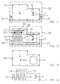
- FIG. 1 is a top view of a base plate
- FIG. 2 is a top view 3 shows a top view of a cover plate
- FIG. 4 shows a detailed view of the middle part of FIG. 2 a first embodiment of the device according to the invention
- Fig. 5 is a plan view of a cover plate
- Fig. 6 is a Top view of a central part
- Fig. 7 is a plan view of a Base plate
- Fig. 8 is a sectional view taken along the line VIII-VIII of Fig. 7 of a second embodiment of the invention Device
- Fig. 9 is a profile view of the cover plate 3 and 5
- Fig. 10 is a plan view of a Cover plate
- Fig. 11 is a plan view of a central part
- Fig. 12 is a plan view of a base plate of a third embodiment show the device of the invention.
- Fig. 1 represents one of the two counterholders, the is designated by 2 and the one from a section 6 slightly outward-curved rag with an inward-pointing one small bulge (dent) 7 has.
- the section 6 has an edge 4 acting as an abutment.
- Rivets for connecting the counterholders.
- At 25 is denotes the area in which the coding is affixed is.
- a possible check card edge is marked with 22 and dotted executed. This indicates that the device be built into a punched out check card could use the existing coding.
- FIG. 2 shows the slide-like part 1 framed by the spacer 13, also a compression spring 10 and additionally a tension spring (Rubber band) 23, which is in a cutout 24 of the slide 1 is housed and with one end on the slide and with the other on the right, on the counterholder underneath 2 is attached.
- This is due to thick dots 26 (Gluing points) indicated in Fig. 2.
- the invention encompasses also arrangements that have only a single spring. The advantage of two springs is the stronger force and the reserve in the event of a spring break.
- the invention The device is in the ATM like a credit card treated and comes through the contacts to be cleaned of the ATM. Due to the pressure exerted by the ATM the dent 7 is pressed against the locking tab 5, whereby this comes free from the abutment edge, whereupon the Slide under the action of springs 10 and 23 in its other end position moved.
- the cleaning element is painted 15, e.g. a thin glass fiber tile or the like or also just a fine, rough coat of paint on slide 1 over the parts to be cleaned Contacts. Instead of the riveting marked 13 gluing or welding could also occur.
- Fig. 4 shows another embodiment of the slide 1 with molded spring 10.
- the spring 10 sits on the Bottom of the slider 1 firmly, what to avoid a Canting is cheaper if there are two springs.
- a cutout 20 is used only for a better hold of the device, if inserted into a punched out check card becomes.
- the check card and the device are dispensed with provide the necessary code yourself, so this section falls 20 away and the outer outline of the device is the same that of a check card (Fig. 10 to 12). This outline is in 1 and 2 designated 22.
- FIG. 5 to 7 show a further exemplary embodiment of the invention.
- a part 1 ' which can be pivoted about an axis 17 is provided, which carries a cleaning element 15' on its one outer region and which has a notch 27 into which a compression spring 10 engages, which engages against the Spacer 13 'is supported.
- the rotary valve 1 ' shown in FIG. 6 it is locked. Its locking part 5 'rests on the edge 4 of the abutment (FIG. 7) on the counter-holder 2.
- part 3 there is again a small slot 8 'in the direction of movement of the slide, that is to say an arcuate design here, through which a pin can be inserted in order to reset the slide.
- this slot 8 ' there is again a small bore 9 or the like in the rotary valve 1', in which the pin can engage.
- Part 2 (Fig. 7) is to be thought of under the rotary valve 1 'and part 3 above the valve 1' (Fig. 6).
- FIG. 8 shows a section of part 2 along the line VIII - VIII in Fig. 7.
- the locking part lies on a bulge 7 ' 5 'with the device assembled, if the Rotary valve 1 'is in the position shown (Fig. 6).
- the locking part 5 'of the Abutment edge 4 pushed away and the rotary valve 1 'moves itself under the action of the spring 10 and any Tension spring 23 (e.g. a rubber band) in its other end position, the is fixed by the stop on the spacer. It strokes its cleaning element 15 'over the under a window 14' contacts to be cleaned of the chip card reader or ATMs.
- This window 14 ' is dashed in Fig. 6 indicated, but is in part 3 (Fig. 5).
- Fig. 9 shows part 3 in cross section in the case of it simultaneously with the edges 28 represents the spacer that is as an independent part.
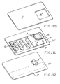
- FIGS. 10 to 12 show a third embodiment of the device according to the invention.
- it has the form of a check card and is provided with the necessary coding 25 '.
- the cover plate 3 "forms the upper counter-holder and is provided in an analogous manner according to FIGS. 3 and 5 with a window 14" and in a manner not shown with a slot. 1, but in a different arrangement, the base plate 2 "forming the other counter-holder is provided with a tab 7" which is bent upwards.
- the slide 1 is equipped with an abutment 4" and a tab 6 ", which carries the cleaning element 15" and the base plate 2 "is bent in the same direction as the tab 7".
- the rotary valve 1 could also be circular or be circular, driven by a coil spring (preferably made as shown in FIG. 4 Compression spring 10) so that the cleaning part also some rotation could exercise, if the arrangement of the contacts in the ATMs allow this.
Landscapes
- Engineering & Computer Science (AREA)
- Physics & Mathematics (AREA)
- General Physics & Mathematics (AREA)
- Theoretical Computer Science (AREA)
- Artificial Intelligence (AREA)
- Computer Vision & Pattern Recognition (AREA)
- Coupling Device And Connection With Printed Circuit (AREA)
- Automatic Analysis And Handling Materials Therefor (AREA)
- Accessory Devices And Overall Control Thereof (AREA)
- Conveying Record Carriers (AREA)
- Facsimile Heads (AREA)
Description
Der Teil 2 (Fig. 7) ist unter dem Drehschieber 1' zu denken und der Teil 3 über dem Schieber 1' (Fig. 6).
Wie in Fig. 11 gezeigt ist der Schieber 1" mit einem Widerlager 4" und einem Lappen 6" ausgestattet, der das Reinigungselement 15" trägt und gleichsinnig wie der Lappen 7" die Grundplatte 2" aufgebogen ist. In der arretierten Stellung des Schiebers 1" liegt der Lappen 7" am Widerlager 4" an und drückt gegen den Lappen 6". Gleichzeitig wird der Lappen 7" vom Widerlager 4" weggedrückt, so daß der Schieber 1" entarretiert und mittels der Feder 10 in die in Fig. 11 dargestellte Lage verschoben wird. Durch Eingriff mit einem Stift od. dgl. in das Loch 9" ist die arretierte, vorgespannte Lage des Schiebers 1" wieder herstellbar.
Claims (22)
- Vorrichtung zum Reinigen der elektrischen Kontakte eines Lesegerätes für Chipkarten- oder Chip-Scheckkarten, vorzugsweise in Bankomaten, wobei die Außenmaße der Vorrichtung so bemessen sind, daß sie in den Schlitz des Lesegerätes einführbar ist, wobei sie gegebenenfalls mit einer Codierung versehen ist, und welche Vorrichtung ein Reinigungselement (15,15',15") umfaßt, das über die Kontakte des Lesegerätes bewegbar ist, dadurch gekennzeichnet, daß die Vorrichtung zwei zueinander bewegliche Teile aufweist, wobei ein erster Teil ein Gegenhalter (2,2'2") für einen zweiten Teil (1,1',1") ist, der schieberartig ausgebildet ist und das Reinigungselement (15,15',15") trägt.
- Vorrichtung nach Anspruch 1, dadurch gekennzeichnet, daß der schieberartige Teil (1,1',1") unter der Einwirkung von zumindest einer Feder (10, 23) steht und entweder geradlinig bewegbar oder um eine Achse (17) drehbar ist, daß er in seiner Ausgangsstellung vorzugsweise verriegelt und durch Einwirkung der Kontakte des Lesegerätes entriegelbar ist, so daß der schieberartige Teil (1, 1', 1") sich unter der Wirkung der zumindest einen Feder (10, 23) über die Kontakte des Lesegerätes bewegt.
- Vorrichtung nach Anspruch 1 oder 2, dadurch gekennzeichnet, daß der schieberartige Teil (1) zwischen zwei miteinander über einen Abstandhalter (13) od.dgl. verbundenen Teilen (2, 3) sitzt, deren einer ein Widerlager (4) für einen am schieberartigen Teil (1) befindlichen Arretierungsteil (5) trägt und deren anderer (3) als Gegenhalter für den schieberartigen Teil (1) dient.
- Vorrichtung nach Anspruch 3, dadurch gekennzeichnet, daß einer der beiden außen befindlichen Teile (2, 3) an den Rändern zumindest teilweise hochgezogen und umgekantet ist und so den Abstandhalter bildet.
- Vorrichtung nach einem der Ansprüche 2 bis 4, dadurch gekennzeichnet, daß der schieberartige Teil (1) aus korrosionsbeständigem federndem Material, vorzugsweise Edelstahlblech besteht und daß der aus der Hauptebene dieses Teiles (1) etwas herausgebogene Arretierungsteil (5) mit einem vorzugsweise als Kante eines Ausschnittes (6) ausgebildeten Widerlager (4) am Gegenhalter (3) zusammenwirkt.
- Vorrichtung nach Anspruch 5, dadurch gekennzeichnet, daß die der Widerlagerkante gegenüberliegende Seite desselben Ausschnittes (6) bzw. der Ausstanzung ein Entriegelungselement bildet und in gleicher Richtung wie der Arretierungsteil (5) aus der Hauptebene herausgebogen ist und vorzugsweise eine kleine, am aufgebogenen Arretierungsteil (5) anliegende Aufwölbung oder Delle (7) trägt.
- Vorrichtung nach einem oder mehreren der Ansprüche 2 bis 6, dadurch gekennzeichnet, daß der den schieberartigen Teil (1) haltende Teil (3) einen in Bewegungsrichtung des Schiebers od.dgl. verlaufenden Schlitz (8) aufweist, unter dem der schieberartige Teil (1) eine kleine Bohrung oder einen kurzen Schlitz (9) besitzt, welcher zur händischen Rückstellung des schieberartigen Teiles (1) in seine Ausgangsstellung dient.
- Vorrichtung nach einem der Ansprüche 3 bis 7, dadurch gekennzeichnet, daß der das Widerlager aufweisende Gegenhalter (2) aus federndem Material, vorzugsweise nicht rostendem Stahlblech besteht.
- Vorrichtung nach einem oder mehreren der Ansprüche 2 bis 8, dadurch gekennzeichnet, daß eine zur Betätigung des Schiebers (1) dienende Feder (10) eine mäanderförmig ausgebildete flache Druckfeder ist.
- Vorrichtung nach einem oder mehreren der Ansprüche 2 bis 9, dadurch gekennzeichnet, daß eine Feder eine Zugfeder, z.B. ein Gummiband ist und mit einem Ende am Schieber (1) und mit dem anderen an einem der Außenteile (2, 3) befestigt, vorzugsweise angeklebt ist.
- Vorrichtung nach einem der Ansprüche 2 bis 10, dadurch gekennzeichnet, daß der Träger des Reinigungselementes (15) verdrehbar angeordnet ist und hierfür eine Druckfeder (10) oder eine Spiralfeder vorgesehen ist.
- Vorrichtung nach einem oder mehreren der Ansprüche 1 bis 11, dadurch gekennzeichnet, daß der eine Gegenhalter, d.h. Außenteil (3) einen Ausschnitt bzw. Fenster (14) aufweist, in dessen Bereich das Reinigungselement bewegbar ist.
- Vorrichtung nach einem der Ansprüche 2 bis 12, dadurch gekennzeichnet, daß der schieberartige Teil (1) zusammen mit mindestens einer Feder (10) im Raum zwischen den beiden äußeren Gegenhaltern (2, 3) angeordnet ist.
- Vorrichtung nach Anspruch 13, dadurch gekennzeichnet, daß der schieberartige Teil (1) an dem einen der beiden außen liegenden Gegenhalter (2, 3) verschieblich befestigt ist, z.B. in Schlitze desselben eingreift.
- Vorrichtung nach einem der Ansprüche 2 bis 13, dadurch gekennzeichnet, daß eine Feder (10) am schieberartigen Teil (1) selbst angeformt ist.
- Vorrichtung nach Anspruch 15, dadurch gekennzeichnet, daß eine Feder (10) flach und mäanderförmig ausgebildet ist.
- Vorrichtung nach Anspruch 10, dadurch gekennzeichnet, daß die als elastisches Band ausgebildete Feder (23) in einem seitlichen Ausschnitt (24) des schieberartigen Teiles (1) untergebracht ist.
- Vorrichtung nach einem der Ansprüche 3 bis 17, dadurch gekennzeichnet, daß der Abstandhalter (13) als Führung für den schieberartigen Teil (1) dient.
- Vorrichtung nach Anspruch 11, dadurch gekennzeichnet, daß der schieberartige Teil (1) als Drehhebel ausgebildet ist, der im Endbereich ein Reinigungselement trägt und der im wesentlichen quer zur Längsausdehnung der Vorrichtung um etwa 20 bis 30 Grad verschwenkbar ist.
- Vorrichtung nach Anspruch 19, dadurch gekennzeichnet, daß der Drehhebel mittels einer flachen Druckfeder (10) gegen den Abstandhalter abgestützt ist und daß in seinem äußeren Bereich ein Arretierungselement (5) angeordnet ist, das mit einem Widerlager (4) des einen Gegenhalters (2) zusammenwirkt.
- Vorrichtung nach Anspruch 19, dadurch gekennzeichnet, daß zum Antrieb des Drehhebels an Stelle einer Druckfeder (10) eine Spiralfeder angeordnet ist.
- Vorrichtung nach Anspruch 1, dadurch gekennzeichnet, daß der das Reinigungselement tragende schieberartige Teil so lang ausgebildet ist, daß er aus dem Schlitz des Lesegerätes ragt und von außen durch eine Bedienerperson bewegt werden kann.
Applications Claiming Priority (3)
| Application Number | Priority Date | Filing Date | Title |
|---|---|---|---|
| AT227/96 | 1996-02-08 | ||
| AT0022796A AT411633B (de) | 1996-02-08 | 1996-02-08 | Vorrichtung zum reinigen der chip-checkkarten kontrollierenden elektrischen kontakte von bankomaten |
| AT22796 | 1996-02-08 |
Publications (3)
| Publication Number | Publication Date |
|---|---|
| EP0789313A2 EP0789313A2 (de) | 1997-08-13 |
| EP0789313A3 EP0789313A3 (de) | 2000-02-23 |
| EP0789313B1 true EP0789313B1 (de) | 2003-01-08 |
Family
ID=3484934
Family Applications (1)
| Application Number | Title | Priority Date | Filing Date |
|---|---|---|---|
| EP97890019A Expired - Lifetime EP0789313B1 (de) | 1996-02-08 | 1997-02-06 | Vorrichtung zum Reinigen der elektrischen Kontakte eines Chipkartenlesegerätes |
Country Status (3)
| Country | Link |
|---|---|
| EP (1) | EP0789313B1 (de) |
| AT (2) | AT411633B (de) |
| DE (1) | DE59709065D1 (de) |
Cited By (1)
| Publication number | Priority date | Publication date | Assignee | Title |
|---|---|---|---|---|
| US11710011B2 (en) | 2021-02-12 | 2023-07-25 | Kicteam, Inc. | Media transport device cleaning card with raised surface element |
Families Citing this family (1)
| Publication number | Priority date | Publication date | Assignee | Title |
|---|---|---|---|---|
| DE102007028578A1 (de) * | 2007-06-19 | 2008-12-24 | Continental Automotive Gmbh | Chipkartenaufnahmesystem |
Family Cites Families (5)
| Publication number | Priority date | Publication date | Assignee | Title |
|---|---|---|---|---|
| IE832705L (en) * | 1983-11-18 | 1985-05-18 | Ryan Plastics Ireland | Cleaning apparatus for a disc drive |
| US4875125A (en) * | 1987-10-14 | 1989-10-17 | Pericomp Corporation | Tape head cleaner cartridge |
| GB2238984A (en) * | 1989-12-12 | 1991-06-19 | Automation Facilities Ltd | Cleaning card for magnetic data reading heads |
| BE1005549A6 (nl) * | 1990-12-07 | 1993-10-26 | Bell Telephone Mfg | Elektrische contactinrichting. |
| FR2718679B1 (fr) * | 1994-04-15 | 1996-05-24 | Gemplus Card Int | Carte de nettoyage pour machine à imprimer et poste de personnalisation électrique des cartes. |
-
1996
- 1996-02-08 AT AT0022796A patent/AT411633B/de not_active IP Right Cessation
-
1997
- 1997-02-06 DE DE59709065T patent/DE59709065D1/de not_active Expired - Lifetime
- 1997-02-06 AT AT97890019T patent/ATE230865T1/de active
- 1997-02-06 EP EP97890019A patent/EP0789313B1/de not_active Expired - Lifetime
Cited By (2)
| Publication number | Priority date | Publication date | Assignee | Title |
|---|---|---|---|---|
| US11710011B2 (en) | 2021-02-12 | 2023-07-25 | Kicteam, Inc. | Media transport device cleaning card with raised surface element |
| US11816513B2 (en) | 2021-02-12 | 2023-11-14 | Kicteam, Inc. | Cleaning tool for chip card reader |
Also Published As
| Publication number | Publication date |
|---|---|
| ATE230865T1 (de) | 2003-01-15 |
| DE59709065D1 (de) | 2003-02-13 |
| EP0789313A3 (de) | 2000-02-23 |
| AT411633B (de) | 2004-03-25 |
| ATA22796A (de) | 2003-08-15 |
| EP0789313A2 (de) | 1997-08-13 |
Similar Documents
| Publication | Publication Date | Title |
|---|---|---|
| DE19516987A1 (de) | Kartenlesevorrichtung für Chipkarten und/oder SIM-Karten mit unterschiedlicher Dicke | |
| DE3910880C2 (de) | ||
| EP0258323B1 (de) | Handstempel mit selbstfärbeeinrichtung | |
| EP1353806B1 (de) | Selbstfärbe-handstempel mit einem schwenkbaren typenaggregat und garnitur mit einem solchen selbstfärbestempel | |
| EP0789313B1 (de) | Vorrichtung zum Reinigen der elektrischen Kontakte eines Chipkartenlesegerätes | |
| EP1363226A1 (de) | Kartenlesevorrichtung | |
| DE2214189A1 (de) | Vorschubvorrichtung für eine Informationsträgerkarte | |
| DE3045212C2 (de) | ||
| DE3045211C2 (de) | ||
| EP0034755A1 (de) | Berechtigungskarte | |
| DE4040082A1 (de) | Vorrichtung zum lesen und/oder schreiben von markierungen, informationen o. dgl. auf karten | |
| DE2721806C2 (de) | Lärmmindernde Feder für eine Scheibenbremse | |
| DE102007038352A1 (de) | Schlitzabdeckung | |
| DE925322C (de) | Lochwerkzeug, insbesondere Lochzange, zur Herstellung von gelochten Belegen | |
| DE8218793U1 (de) | Aufreihvorrichtung fuer briefordner oder dgl. | |
| DE3808042C2 (de) | ||
| DE3247781C3 (de) | Vorrichtung zum automatischen Ablesen von Scheckkarten od.dgl. | |
| DE803059C (de) | Vorrichtung zum Anzeichnen von Waeschestuecken | |
| DE964771C (de) | Karteiblattregister mit Waehlvorrichtung | |
| DE924209C (de) | Locher mit Vorrichtung zum Verstaerken der Lochraender mittels Klebestreifen | |
| DE9400348U1 (de) | Anordnung zum Lesen und Auswerten von Chipkarten | |
| DE3535095A1 (de) | Einrichtung zum gleichzeitigen erfassen von arbeitszeiten | |
| EP1257966A1 (de) | Kartenleser mit an schwenkarmen gelagerten transportrollen | |
| DE9400349U1 (de) | Kontaktanordnung für einen Chipkartenleser | |
| DE930028C (de) | Vorrichtung zum Ausstanzen von Kennmarken in Karteikarten |
Legal Events
| Date | Code | Title | Description |
|---|---|---|---|
| PUAI | Public reference made under article 153(3) epc to a published international application that has entered the european phase |
Free format text: ORIGINAL CODE: 0009012 |
|
| AK | Designated contracting states |
Kind code of ref document: A2 Designated state(s): AT CH DE FR GB IT LI NL |
|
| PUAL | Search report despatched |
Free format text: ORIGINAL CODE: 0009013 |
|
| AK | Designated contracting states |
Kind code of ref document: A3 Designated state(s): AT CH DE FR GB IT LI NL |
|
| RIC1 | Information provided on ipc code assigned before grant |
Free format text: 7G 06K 7/06 A, 7G 06K 19/02 B, 7G 06K 7/00 B |
|
| RAP1 | Party data changed (applicant data changed or rights of an application transferred) |
Owner name: KRKNJAK, ALEXANDER |
|
| 17P | Request for examination filed |
Effective date: 20000821 |
|
| 17Q | First examination report despatched |
Effective date: 20010727 |
|
| GRAG | Despatch of communication of intention to grant |
Free format text: ORIGINAL CODE: EPIDOS AGRA |
|
| GRAG | Despatch of communication of intention to grant |
Free format text: ORIGINAL CODE: EPIDOS AGRA |
|
| GRAG | Despatch of communication of intention to grant |
Free format text: ORIGINAL CODE: EPIDOS AGRA |
|
| GRAH | Despatch of communication of intention to grant a patent |
Free format text: ORIGINAL CODE: EPIDOS IGRA |
|
| GRAH | Despatch of communication of intention to grant a patent |
Free format text: ORIGINAL CODE: EPIDOS IGRA |
|
| GRAA | (expected) grant |
Free format text: ORIGINAL CODE: 0009210 |
|
| AK | Designated contracting states |
Kind code of ref document: B1 Designated state(s): AT CH DE FR GB IT LI NL |
|
| PG25 | Lapsed in a contracting state [announced via postgrant information from national office to epo] |
Ref country code: NL Free format text: LAPSE BECAUSE OF FAILURE TO SUBMIT A TRANSLATION OF THE DESCRIPTION OR TO PAY THE FEE WITHIN THE PRESCRIBED TIME-LIMIT Effective date: 20030108 |
|
| REF | Corresponds to: |
Ref document number: 230865 Country of ref document: AT Date of ref document: 20030115 Kind code of ref document: T |
|
| REG | Reference to a national code |
Ref country code: GB Ref legal event code: FG4D Free format text: NOT ENGLISH |
|
| REG | Reference to a national code |
Ref country code: CH Ref legal event code: EP |
|
| REG | Reference to a national code |
Ref country code: CH Ref legal event code: NV Representative=s name: E. BLUM & CO. PATENTANWAELTE |
|
| REF | Corresponds to: |
Ref document number: 59709065 Country of ref document: DE Date of ref document: 20030213 Kind code of ref document: P |
|
| GBT | Gb: translation of ep patent filed (gb section 77(6)(a)/1977) |
Effective date: 20030204 |
|
| ET | Fr: translation filed | ||
| PLBE | No opposition filed within time limit |
Free format text: ORIGINAL CODE: 0009261 |
|
| STAA | Information on the status of an ep patent application or granted ep patent |
Free format text: STATUS: NO OPPOSITION FILED WITHIN TIME LIMIT |
|
| 26N | No opposition filed |
Effective date: 20031009 |
|
| REG | Reference to a national code |
Ref country code: CH Ref legal event code: PFA Owner name: KRKNJAK, ALEXANDER Free format text: KRKNJAK, ALEXANDER#MAYRHOF 8#4873 FRANKENBURG (AT) -TRANSFER TO- KRKNJAK, ALEXANDER#MAYRHOF 8#4873 FRANKENBURG (AT) |
|
| PGFP | Annual fee paid to national office [announced via postgrant information from national office to epo] |
Ref country code: FR Payment date: 20140131 Year of fee payment: 18 Ref country code: IT Payment date: 20140221 Year of fee payment: 18 |
|
| PGFP | Annual fee paid to national office [announced via postgrant information from national office to epo] |
Ref country code: GB Payment date: 20140130 Year of fee payment: 18 |
|
| GBPC | Gb: european patent ceased through non-payment of renewal fee |
Effective date: 20150206 |
|
| REG | Reference to a national code |
Ref country code: FR Ref legal event code: ST Effective date: 20151030 |
|
| PG25 | Lapsed in a contracting state [announced via postgrant information from national office to epo] |
Ref country code: IT Free format text: LAPSE BECAUSE OF NON-PAYMENT OF DUE FEES Effective date: 20150206 |
|
| PG25 | Lapsed in a contracting state [announced via postgrant information from national office to epo] |
Ref country code: GB Free format text: LAPSE BECAUSE OF NON-PAYMENT OF DUE FEES Effective date: 20150206 |
|
| PG25 | Lapsed in a contracting state [announced via postgrant information from national office to epo] |
Ref country code: FR Free format text: LAPSE BECAUSE OF NON-PAYMENT OF DUE FEES Effective date: 20150302 |
|
| PGFP | Annual fee paid to national office [announced via postgrant information from national office to epo] |
Ref country code: CH Payment date: 20160106 Year of fee payment: 20 |
|
| PGFP | Annual fee paid to national office [announced via postgrant information from national office to epo] |
Ref country code: AT Payment date: 20160121 Year of fee payment: 20 |
|
| PGFP | Annual fee paid to national office [announced via postgrant information from national office to epo] |
Ref country code: DE Payment date: 20160330 Year of fee payment: 20 |
|
| REG | Reference to a national code |
Ref country code: DE Ref legal event code: R071 Ref document number: 59709065 Country of ref document: DE |
|
| REG | Reference to a national code |
Ref country code: CH Ref legal event code: PL |
|
| REG | Reference to a national code |
Ref country code: AT Ref legal event code: MK07 Ref document number: 230865 Country of ref document: AT Kind code of ref document: T Effective date: 20170206 |