EP0785587B1 - Gesinterter Mehrschichtkörper für elektrochemische Zelle, elektrochemische Zelle damit und Verfahren ihrer Herstellung - Google Patents
Gesinterter Mehrschichtkörper für elektrochemische Zelle, elektrochemische Zelle damit und Verfahren ihrer Herstellung Download PDFInfo
- Publication number
- EP0785587B1 EP0785587B1 EP97300239A EP97300239A EP0785587B1 EP 0785587 B1 EP0785587 B1 EP 0785587B1 EP 97300239 A EP97300239 A EP 97300239A EP 97300239 A EP97300239 A EP 97300239A EP 0785587 B1 EP0785587 B1 EP 0785587B1
- Authority
- EP
- European Patent Office
- Prior art keywords
- separator
- electrode
- layered
- grooves
- sintered body
- Prior art date
- Legal status (The legal status is an assumption and is not a legal conclusion. Google has not performed a legal analysis and makes no representation as to the accuracy of the status listed.)
- Expired - Lifetime
Links
Images


Classifications
-
- B—PERFORMING OPERATIONS; TRANSPORTING
- B01—PHYSICAL OR CHEMICAL PROCESSES OR APPARATUS IN GENERAL
- B01D—SEPARATION
- B01D53/00—Separation of gases or vapours; Recovering vapours of volatile solvents from gases; Chemical or biological purification of waste gases, e.g. engine exhaust gases, smoke, fumes, flue gases, aerosols
- B01D53/32—Separation of gases or vapours; Recovering vapours of volatile solvents from gases; Chemical or biological purification of waste gases, e.g. engine exhaust gases, smoke, fumes, flue gases, aerosols by electrical effects other than those provided for in group B01D61/00
- B01D53/326—Separation of gases or vapours; Recovering vapours of volatile solvents from gases; Chemical or biological purification of waste gases, e.g. engine exhaust gases, smoke, fumes, flue gases, aerosols by electrical effects other than those provided for in group B01D61/00 in electrochemical cells
-
- B—PERFORMING OPERATIONS; TRANSPORTING
- B32—LAYERED PRODUCTS
- B32B—LAYERED PRODUCTS, i.e. PRODUCTS BUILT-UP OF STRATA OF FLAT OR NON-FLAT, e.g. CELLULAR OR HONEYCOMB, FORM
- B32B18/00—Layered products essentially comprising ceramics, e.g. refractory products
-
- C—CHEMISTRY; METALLURGY
- C04—CEMENTS; CONCRETE; ARTIFICIAL STONE; CERAMICS; REFRACTORIES
- C04B—LIME, MAGNESIA; SLAG; CEMENTS; COMPOSITIONS THEREOF, e.g. MORTARS, CONCRETE OR LIKE BUILDING MATERIALS; ARTIFICIAL STONE; CERAMICS; REFRACTORIES; TREATMENT OF NATURAL STONE
- C04B35/00—Shaped ceramic products characterised by their composition; Ceramics compositions; Processing powders of inorganic compounds preparatory to the manufacturing of ceramic products
- C04B35/01—Shaped ceramic products characterised by their composition; Ceramics compositions; Processing powders of inorganic compounds preparatory to the manufacturing of ceramic products based on oxide ceramics
-
- C—CHEMISTRY; METALLURGY
- C04—CEMENTS; CONCRETE; ARTIFICIAL STONE; CERAMICS; REFRACTORIES
- C04B—LIME, MAGNESIA; SLAG; CEMENTS; COMPOSITIONS THEREOF, e.g. MORTARS, CONCRETE OR LIKE BUILDING MATERIALS; ARTIFICIAL STONE; CERAMICS; REFRACTORIES; TREATMENT OF NATURAL STONE
- C04B35/00—Shaped ceramic products characterised by their composition; Ceramics compositions; Processing powders of inorganic compounds preparatory to the manufacturing of ceramic products
- C04B35/622—Forming processes; Processing powders of inorganic compounds preparatory to the manufacturing of ceramic products
- C04B35/64—Burning or sintering processes
- C04B35/645—Pressure sintering
-
- C—CHEMISTRY; METALLURGY
- C25—ELECTROLYTIC OR ELECTROPHORETIC PROCESSES; APPARATUS THEREFOR
- C25B—ELECTROLYTIC OR ELECTROPHORETIC PROCESSES FOR THE PRODUCTION OF COMPOUNDS OR NON-METALS; APPARATUS THEREFOR
- C25B1/00—Electrolytic production of inorganic compounds or non-metals
- C25B1/01—Products
- C25B1/02—Hydrogen or oxygen
- C25B1/04—Hydrogen or oxygen by electrolysis of water
- C25B1/042—Hydrogen or oxygen by electrolysis of water by electrolysis of steam
-
- C—CHEMISTRY; METALLURGY
- C25—ELECTROLYTIC OR ELECTROPHORETIC PROCESSES; APPARATUS THEREFOR
- C25B—ELECTROLYTIC OR ELECTROPHORETIC PROCESSES FOR THE PRODUCTION OF COMPOUNDS OR NON-METALS; APPARATUS THEREFOR
- C25B9/00—Cells or assemblies of cells; Constructional parts of cells; Assemblies of constructional parts, e.g. electrode-diaphragm assemblies; Process-related cell features
- C25B9/17—Cells comprising dimensionally-stable non-movable electrodes; Assemblies of constructional parts thereof
- C25B9/19—Cells comprising dimensionally-stable non-movable electrodes; Assemblies of constructional parts thereof with diaphragms
- C25B9/23—Cells comprising dimensionally-stable non-movable electrodes; Assemblies of constructional parts thereof with diaphragms comprising ion-exchange membranes in or on which electrode material is embedded
-
- H—ELECTRICITY
- H01—ELECTRIC ELEMENTS
- H01M—PROCESSES OR MEANS, e.g. BATTERIES, FOR THE DIRECT CONVERSION OF CHEMICAL ENERGY INTO ELECTRICAL ENERGY
- H01M8/00—Fuel cells; Manufacture thereof
- H01M8/02—Details
- H01M8/0202—Collectors; Separators, e.g. bipolar separators; Interconnectors
- H01M8/0204—Non-porous and characterised by the material
- H01M8/0215—Glass; Ceramic materials
- H01M8/0217—Complex oxides, optionally doped, of the type AMO3, A being an alkaline earth metal or rare earth metal and M being a metal, e.g. perovskites
-
- H—ELECTRICITY
- H01—ELECTRIC ELEMENTS
- H01M—PROCESSES OR MEANS, e.g. BATTERIES, FOR THE DIRECT CONVERSION OF CHEMICAL ENERGY INTO ELECTRICAL ENERGY
- H01M8/00—Fuel cells; Manufacture thereof
- H01M8/02—Details
- H01M8/0202—Collectors; Separators, e.g. bipolar separators; Interconnectors
- H01M8/0247—Collectors; Separators, e.g. bipolar separators; Interconnectors characterised by the form
-
- H—ELECTRICITY
- H01—ELECTRIC ELEMENTS
- H01M—PROCESSES OR MEANS, e.g. BATTERIES, FOR THE DIRECT CONVERSION OF CHEMICAL ENERGY INTO ELECTRICAL ENERGY
- H01M8/00—Fuel cells; Manufacture thereof
- H01M8/02—Details
- H01M8/0202—Collectors; Separators, e.g. bipolar separators; Interconnectors
- H01M8/0258—Collectors; Separators, e.g. bipolar separators; Interconnectors characterised by the configuration of channels, e.g. by the flow field of the reactant or coolant
- H01M8/026—Collectors; Separators, e.g. bipolar separators; Interconnectors characterised by the configuration of channels, e.g. by the flow field of the reactant or coolant characterised by grooves, e.g. their pitch or depth
-
- H—ELECTRICITY
- H01—ELECTRIC ELEMENTS
- H01M—PROCESSES OR MEANS, e.g. BATTERIES, FOR THE DIRECT CONVERSION OF CHEMICAL ENERGY INTO ELECTRICAL ENERGY
- H01M8/00—Fuel cells; Manufacture thereof
- H01M8/02—Details
- H01M8/0297—Arrangements for joining electrodes, reservoir layers, heat exchange units or bipolar separators to each other
-
- H—ELECTRICITY
- H01—ELECTRIC ELEMENTS
- H01M—PROCESSES OR MEANS, e.g. BATTERIES, FOR THE DIRECT CONVERSION OF CHEMICAL ENERGY INTO ELECTRICAL ENERGY
- H01M8/00—Fuel cells; Manufacture thereof
- H01M8/10—Fuel cells with solid electrolytes
- H01M8/12—Fuel cells with solid electrolytes operating at high temperature, e.g. with stabilised ZrO2 electrolyte
- H01M8/1213—Fuel cells with solid electrolytes operating at high temperature, e.g. with stabilised ZrO2 electrolyte characterised by the electrode/electrolyte combination or the supporting material
-
- H—ELECTRICITY
- H01—ELECTRIC ELEMENTS
- H01M—PROCESSES OR MEANS, e.g. BATTERIES, FOR THE DIRECT CONVERSION OF CHEMICAL ENERGY INTO ELECTRICAL ENERGY
- H01M8/00—Fuel cells; Manufacture thereof
- H01M8/24—Grouping of fuel cells, e.g. stacking of fuel cells
- H01M8/241—Grouping of fuel cells, e.g. stacking of fuel cells with solid or matrix-supported electrolytes
- H01M8/2425—High-temperature cells with solid electrolytes
- H01M8/2435—High-temperature cells with solid electrolytes with monolithic core structure, e.g. honeycombs
-
- H—ELECTRICITY
- H01—ELECTRIC ELEMENTS
- H01M—PROCESSES OR MEANS, e.g. BATTERIES, FOR THE DIRECT CONVERSION OF CHEMICAL ENERGY INTO ELECTRICAL ENERGY
- H01M8/00—Fuel cells; Manufacture thereof
- H01M8/24—Grouping of fuel cells, e.g. stacking of fuel cells
- H01M8/2457—Grouping of fuel cells, e.g. stacking of fuel cells with both reactants being gaseous or vaporised
-
- C—CHEMISTRY; METALLURGY
- C04—CEMENTS; CONCRETE; ARTIFICIAL STONE; CERAMICS; REFRACTORIES
- C04B—LIME, MAGNESIA; SLAG; CEMENTS; COMPOSITIONS THEREOF, e.g. MORTARS, CONCRETE OR LIKE BUILDING MATERIALS; ARTIFICIAL STONE; CERAMICS; REFRACTORIES; TREATMENT OF NATURAL STONE
- C04B2235/00—Aspects relating to ceramic starting mixtures or sintered ceramic products
- C04B2235/65—Aspects relating to heat treatments of ceramic bodies such as green ceramics or pre-sintered ceramics, e.g. burning, sintering or melting processes
- C04B2235/656—Aspects relating to heat treatments of ceramic bodies such as green ceramics or pre-sintered ceramics, e.g. burning, sintering or melting processes characterised by specific heating conditions during heat treatment
- C04B2235/6562—Heating rate
-
- C—CHEMISTRY; METALLURGY
- C04—CEMENTS; CONCRETE; ARTIFICIAL STONE; CERAMICS; REFRACTORIES
- C04B—LIME, MAGNESIA; SLAG; CEMENTS; COMPOSITIONS THEREOF, e.g. MORTARS, CONCRETE OR LIKE BUILDING MATERIALS; ARTIFICIAL STONE; CERAMICS; REFRACTORIES; TREATMENT OF NATURAL STONE
- C04B2235/00—Aspects relating to ceramic starting mixtures or sintered ceramic products
- C04B2235/65—Aspects relating to heat treatments of ceramic bodies such as green ceramics or pre-sintered ceramics, e.g. burning, sintering or melting processes
- C04B2235/656—Aspects relating to heat treatments of ceramic bodies such as green ceramics or pre-sintered ceramics, e.g. burning, sintering or melting processes characterised by specific heating conditions during heat treatment
- C04B2235/6567—Treatment time
-
- C—CHEMISTRY; METALLURGY
- C04—CEMENTS; CONCRETE; ARTIFICIAL STONE; CERAMICS; REFRACTORIES
- C04B—LIME, MAGNESIA; SLAG; CEMENTS; COMPOSITIONS THEREOF, e.g. MORTARS, CONCRETE OR LIKE BUILDING MATERIALS; ARTIFICIAL STONE; CERAMICS; REFRACTORIES; TREATMENT OF NATURAL STONE
- C04B2237/00—Aspects relating to ceramic laminates or to joining of ceramic articles with other articles by heating
- C04B2237/02—Aspects relating to interlayers, e.g. used to join ceramic articles with other articles by heating
- C04B2237/04—Ceramic interlayers
- C04B2237/06—Oxidic interlayers
- C04B2237/066—Oxidic interlayers based on rare earth oxides
-
- C—CHEMISTRY; METALLURGY
- C04—CEMENTS; CONCRETE; ARTIFICIAL STONE; CERAMICS; REFRACTORIES
- C04B—LIME, MAGNESIA; SLAG; CEMENTS; COMPOSITIONS THEREOF, e.g. MORTARS, CONCRETE OR LIKE BUILDING MATERIALS; ARTIFICIAL STONE; CERAMICS; REFRACTORIES; TREATMENT OF NATURAL STONE
- C04B2237/00—Aspects relating to ceramic laminates or to joining of ceramic articles with other articles by heating
- C04B2237/30—Composition of layers of ceramic laminates or of ceramic or metallic articles to be joined by heating, e.g. Si substrates
- C04B2237/32—Ceramic
- C04B2237/34—Oxidic
- C04B2237/345—Refractory metal oxides
- C04B2237/346—Titania or titanates
-
- C—CHEMISTRY; METALLURGY
- C04—CEMENTS; CONCRETE; ARTIFICIAL STONE; CERAMICS; REFRACTORIES
- C04B—LIME, MAGNESIA; SLAG; CEMENTS; COMPOSITIONS THEREOF, e.g. MORTARS, CONCRETE OR LIKE BUILDING MATERIALS; ARTIFICIAL STONE; CERAMICS; REFRACTORIES; TREATMENT OF NATURAL STONE
- C04B2237/00—Aspects relating to ceramic laminates or to joining of ceramic articles with other articles by heating
- C04B2237/50—Processing aspects relating to ceramic laminates or to the joining of ceramic articles with other articles by heating
- C04B2237/60—Forming at the joining interface or in the joining layer specific reaction phases or zones, e.g. diffusion of reactive species from the interlayer to the substrate or from a substrate to the joining interface, carbide forming at the joining interface
-
- C—CHEMISTRY; METALLURGY
- C04—CEMENTS; CONCRETE; ARTIFICIAL STONE; CERAMICS; REFRACTORIES
- C04B—LIME, MAGNESIA; SLAG; CEMENTS; COMPOSITIONS THEREOF, e.g. MORTARS, CONCRETE OR LIKE BUILDING MATERIALS; ARTIFICIAL STONE; CERAMICS; REFRACTORIES; TREATMENT OF NATURAL STONE
- C04B2237/00—Aspects relating to ceramic laminates or to joining of ceramic articles with other articles by heating
- C04B2237/50—Processing aspects relating to ceramic laminates or to the joining of ceramic articles with other articles by heating
- C04B2237/64—Forming laminates or joined articles comprising grooves or cuts
-
- C—CHEMISTRY; METALLURGY
- C04—CEMENTS; CONCRETE; ARTIFICIAL STONE; CERAMICS; REFRACTORIES
- C04B—LIME, MAGNESIA; SLAG; CEMENTS; COMPOSITIONS THEREOF, e.g. MORTARS, CONCRETE OR LIKE BUILDING MATERIALS; ARTIFICIAL STONE; CERAMICS; REFRACTORIES; TREATMENT OF NATURAL STONE
- C04B2237/00—Aspects relating to ceramic laminates or to joining of ceramic articles with other articles by heating
- C04B2237/50—Processing aspects relating to ceramic laminates or to the joining of ceramic articles with other articles by heating
- C04B2237/66—Forming laminates or joined articles showing high dimensional accuracy, e.g. indicated by the warpage
-
- C—CHEMISTRY; METALLURGY
- C04—CEMENTS; CONCRETE; ARTIFICIAL STONE; CERAMICS; REFRACTORIES
- C04B—LIME, MAGNESIA; SLAG; CEMENTS; COMPOSITIONS THEREOF, e.g. MORTARS, CONCRETE OR LIKE BUILDING MATERIALS; ARTIFICIAL STONE; CERAMICS; REFRACTORIES; TREATMENT OF NATURAL STONE
- C04B2237/00—Aspects relating to ceramic laminates or to joining of ceramic articles with other articles by heating
- C04B2237/50—Processing aspects relating to ceramic laminates or to the joining of ceramic articles with other articles by heating
- C04B2237/70—Forming laminates or joined articles comprising layers of a specific, unusual thickness
- C04B2237/704—Forming laminates or joined articles comprising layers of a specific, unusual thickness of one or more of the ceramic layers or articles
-
- C—CHEMISTRY; METALLURGY
- C04—CEMENTS; CONCRETE; ARTIFICIAL STONE; CERAMICS; REFRACTORIES
- C04B—LIME, MAGNESIA; SLAG; CEMENTS; COMPOSITIONS THEREOF, e.g. MORTARS, CONCRETE OR LIKE BUILDING MATERIALS; ARTIFICIAL STONE; CERAMICS; REFRACTORIES; TREATMENT OF NATURAL STONE
- C04B2237/00—Aspects relating to ceramic laminates or to joining of ceramic articles with other articles by heating
- C04B2237/50—Processing aspects relating to ceramic laminates or to the joining of ceramic articles with other articles by heating
- C04B2237/76—Forming laminates or joined articles comprising at least one member in the form other than a sheet or disc, e.g. two tubes or a tube and a sheet or disc
-
- H—ELECTRICITY
- H01—ELECTRIC ELEMENTS
- H01M—PROCESSES OR MEANS, e.g. BATTERIES, FOR THE DIRECT CONVERSION OF CHEMICAL ENERGY INTO ELECTRICAL ENERGY
- H01M8/00—Fuel cells; Manufacture thereof
- H01M8/10—Fuel cells with solid electrolytes
- H01M8/12—Fuel cells with solid electrolytes operating at high temperature, e.g. with stabilised ZrO2 electrolyte
- H01M2008/1293—Fuel cells with solid oxide electrolytes
-
- H—ELECTRICITY
- H01—ELECTRIC ELEMENTS
- H01M—PROCESSES OR MEANS, e.g. BATTERIES, FOR THE DIRECT CONVERSION OF CHEMICAL ENERGY INTO ELECTRICAL ENERGY
- H01M2300/00—Electrolytes
- H01M2300/0017—Non-aqueous electrolytes
- H01M2300/0065—Solid electrolytes
- H01M2300/0068—Solid electrolytes inorganic
- H01M2300/0071—Oxides
- H01M2300/0074—Ion conductive at high temperature
-
- H—ELECTRICITY
- H01—ELECTRIC ELEMENTS
- H01M—PROCESSES OR MEANS, e.g. BATTERIES, FOR THE DIRECT CONVERSION OF CHEMICAL ENERGY INTO ELECTRICAL ENERGY
- H01M4/00—Electrodes
- H01M4/86—Inert electrodes with catalytic activity, e.g. for fuel cells
- H01M4/90—Selection of catalytic material
- H01M4/9016—Oxides, hydroxides or oxygenated metallic salts
- H01M4/9025—Oxides specially used in fuel cell operating at high temperature, e.g. SOFC
- H01M4/9033—Complex oxides, optionally doped, of the type M1MeO3, M1 being an alkaline earth metal or a rare earth, Me being a metal, e.g. perovskites
-
- H—ELECTRICITY
- H01—ELECTRIC ELEMENTS
- H01M—PROCESSES OR MEANS, e.g. BATTERIES, FOR THE DIRECT CONVERSION OF CHEMICAL ENERGY INTO ELECTRICAL ENERGY
- H01M4/00—Electrodes
- H01M4/86—Inert electrodes with catalytic activity, e.g. for fuel cells
- H01M4/90—Selection of catalytic material
- H01M4/9041—Metals or alloys
- H01M4/905—Metals or alloys specially used in fuel cell operating at high temperature, e.g. SOFC
- H01M4/9066—Metals or alloys specially used in fuel cell operating at high temperature, e.g. SOFC of metal-ceramic composites or mixtures, e.g. cermets
-
- H—ELECTRICITY
- H01—ELECTRIC ELEMENTS
- H01M—PROCESSES OR MEANS, e.g. BATTERIES, FOR THE DIRECT CONVERSION OF CHEMICAL ENERGY INTO ELECTRICAL ENERGY
- H01M8/00—Fuel cells; Manufacture thereof
- H01M8/02—Details
- H01M8/0202—Collectors; Separators, e.g. bipolar separators; Interconnectors
- H01M8/0204—Non-porous and characterised by the material
- H01M8/0215—Glass; Ceramic materials
- H01M8/0217—Complex oxides, optionally doped, of the type AMO3, A being an alkaline earth metal or rare earth metal and M being a metal, e.g. perovskites
- H01M8/0219—Chromium complex oxides
-
- H—ELECTRICITY
- H01—ELECTRIC ELEMENTS
- H01M—PROCESSES OR MEANS, e.g. BATTERIES, FOR THE DIRECT CONVERSION OF CHEMICAL ENERGY INTO ELECTRICAL ENERGY
- H01M8/00—Fuel cells; Manufacture thereof
- H01M8/02—Details
- H01M8/0271—Sealing or supporting means around electrodes, matrices or membranes
-
- H—ELECTRICITY
- H01—ELECTRIC ELEMENTS
- H01M—PROCESSES OR MEANS, e.g. BATTERIES, FOR THE DIRECT CONVERSION OF CHEMICAL ENERGY INTO ELECTRICAL ENERGY
- H01M8/00—Fuel cells; Manufacture thereof
- H01M8/10—Fuel cells with solid electrolytes
- H01M8/12—Fuel cells with solid electrolytes operating at high temperature, e.g. with stabilised ZrO2 electrolyte
- H01M8/1213—Fuel cells with solid electrolytes operating at high temperature, e.g. with stabilised ZrO2 electrolyte characterised by the electrode/electrolyte combination or the supporting material
- H01M8/1226—Fuel cells with solid electrolytes operating at high temperature, e.g. with stabilised ZrO2 electrolyte characterised by the electrode/electrolyte combination or the supporting material characterised by the supporting layer
-
- H—ELECTRICITY
- H01—ELECTRIC ELEMENTS
- H01M—PROCESSES OR MEANS, e.g. BATTERIES, FOR THE DIRECT CONVERSION OF CHEMICAL ENERGY INTO ELECTRICAL ENERGY
- H01M8/00—Fuel cells; Manufacture thereof
- H01M8/10—Fuel cells with solid electrolytes
- H01M8/12—Fuel cells with solid electrolytes operating at high temperature, e.g. with stabilised ZrO2 electrolyte
- H01M8/124—Fuel cells with solid electrolytes operating at high temperature, e.g. with stabilised ZrO2 electrolyte characterised by the process of manufacturing or by the material of the electrolyte
- H01M8/1246—Fuel cells with solid electrolytes operating at high temperature, e.g. with stabilised ZrO2 electrolyte characterised by the process of manufacturing or by the material of the electrolyte the electrolyte consisting of oxides
- H01M8/1253—Fuel cells with solid electrolytes operating at high temperature, e.g. with stabilised ZrO2 electrolyte characterised by the process of manufacturing or by the material of the electrolyte the electrolyte consisting of oxides the electrolyte containing zirconium oxide
-
- Y—GENERAL TAGGING OF NEW TECHNOLOGICAL DEVELOPMENTS; GENERAL TAGGING OF CROSS-SECTIONAL TECHNOLOGIES SPANNING OVER SEVERAL SECTIONS OF THE IPC; TECHNICAL SUBJECTS COVERED BY FORMER USPC CROSS-REFERENCE ART COLLECTIONS [XRACs] AND DIGESTS
- Y02—TECHNOLOGIES OR APPLICATIONS FOR MITIGATION OR ADAPTATION AGAINST CLIMATE CHANGE
- Y02E—REDUCTION OF GREENHOUSE GAS [GHG] EMISSIONS, RELATED TO ENERGY GENERATION, TRANSMISSION OR DISTRIBUTION
- Y02E60/00—Enabling technologies; Technologies with a potential or indirect contribution to GHG emissions mitigation
- Y02E60/30—Hydrogen technology
- Y02E60/50—Fuel cells
-
- Y—GENERAL TAGGING OF NEW TECHNOLOGICAL DEVELOPMENTS; GENERAL TAGGING OF CROSS-SECTIONAL TECHNOLOGIES SPANNING OVER SEVERAL SECTIONS OF THE IPC; TECHNICAL SUBJECTS COVERED BY FORMER USPC CROSS-REFERENCE ART COLLECTIONS [XRACs] AND DIGESTS
- Y02—TECHNOLOGIES OR APPLICATIONS FOR MITIGATION OR ADAPTATION AGAINST CLIMATE CHANGE
- Y02P—CLIMATE CHANGE MITIGATION TECHNOLOGIES IN THE PRODUCTION OR PROCESSING OF GOODS
- Y02P70/00—Climate change mitigation technologies in the production process for final industrial or consumer products
- Y02P70/50—Manufacturing or production processes characterised by the final manufactured product
-
- Y—GENERAL TAGGING OF NEW TECHNOLOGICAL DEVELOPMENTS; GENERAL TAGGING OF CROSS-SECTIONAL TECHNOLOGIES SPANNING OVER SEVERAL SECTIONS OF THE IPC; TECHNICAL SUBJECTS COVERED BY FORMER USPC CROSS-REFERENCE ART COLLECTIONS [XRACs] AND DIGESTS
- Y10—TECHNICAL SUBJECTS COVERED BY FORMER USPC
- Y10T—TECHNICAL SUBJECTS COVERED BY FORMER US CLASSIFICATION
- Y10T29/00—Metal working
- Y10T29/49—Method of mechanical manufacture
- Y10T29/49002—Electrical device making
- Y10T29/49108—Electric battery cell making
- Y10T29/49114—Electric battery cell making including adhesively bonding
Definitions
- the present invention relates to the improvement of electrochemical cells, such as solid electrolyte fuel cells, water vapor electrolytic cells, oxygen pumps, NOx decomposition cells or the like.
- the solid electrolyte fuel cells i.e. solid oxide fuel cells (SOFC) are roughly classified into two categories: a so-called planar type, and a tubular type.
- SOFC solid oxide fuel cells
- a stack for power generation is constructed by stacking alternately the so-called separators and generator layers.
- generator layers comprising a fuel electrode (anode) and an air electrode (cathode), respectively, are fabricated, interconnectors are also fabricated, and then, a multilayered body is fabricated by stacking alternately the generator layers and interconnectors with interposition therebetween of a membrane comprising ceramic powder and an organic binder. The layered body is then heat-treated to bond the generator layers with the interconnectors.
- a green shaped body for an interconnector is stacked on a green shaped body for a distributor on the air-electrode side, and this stacked body is monolithically sintered to bond the interconnector with the distributor.
- a material having a thermal shrinkage behavior extremely different from those of the green shaped bodies whereby a stress relaxation layer is formed to mitigate stress between the green shaped bodies.
- This stress relaxation layer disintegrates into fine pieces during shrinking upon firing, whereby the stress is mitigated.
- WO94/22177 discloses solid oxide fuel cells of the tubular type.
- the fuel cells are in a stacked array.
- a plurality of interconnecting portions electrically connect the anode and cathode of adjacent cells.
- the fuel cells and the interconnecting portions are formed in a unitary structure.
- the fuel cells are formed by co-extrusion and co-firing of the materials for the anode, cathode, electrolyte and interconnect material.
- Fig. 7a is a schematic cross-sectional view.
- a support of this electrochemical cell is the conjoint body 41.
- This conjoint body 41 is a conjugated body of an air electrode (cathode) 42 with a separator 44.
- the air electrode 42 has a planar shape.
- a plurality of narrow, long banks 44d and 44e are formed on a plate member 44f and grooves are formed between the banks 44d and 44e. With each top face 44c of the banks 44d and 44e, the principal face 42c of the air electrode 42 is bonded. Additionally, 44a is the bottom face of the separator.
- the side face 42b of the air electrode 42 is contiguous to the side face 44b of the separator 44 without difference in level.
- An oxidant gas flow passage 43 has a rectangular or square cross-sectional shape. The end portions of the oxidant gas flow passage 43 are open to the end faces of the separator 44. Additionally, 45 is a joint boundary face.
- a dense solid electrolyte membrane 19 is formed on the conjoint body 41. In this instance, the main portion 19a of the solid electrolyte membrane 19 is formed on the top face 42a of the air electrode 42. Both sides of the main portion 19a are extended to form extended portions 19b which cover the side faces 42b of the air electrode 42 and further the upper portions of the side faces of the separator 44. Consequently, the oxidant gas flow passages 43 are kept airtight excepting the openings thereof.
- a fuel electrode (anode) membrane 20 is formed on the solid electrolyte membrane 19.
- the same problem as the above has been found also in electrochemical cells other than the SOFC.
- the cells are subjected to the heating- cooling cycle between room temperature and 1,000°C, with starting and stopping of the high temperature water vapor electrolytic cells. Therefore, cells having characteristics which would not be deteriorated even under such severe conditions have been expected.
- the task of the present invention is, even when electrochemical cells such as SOFCs or the like are subjected to the repetition of a heating-cooling cycle, for example, from operation at high temperatures exceeding 1,000°C to temperature fall to room temperature, to prevent the layer separation and crack formation on and around the joint boundary between the separator and electrode so that the increase of the internal electric resistance can be restricted.
- a further task is to obviate a possibility of developing cracks in the surroundings of the joint boundary of the electrode and separator.
- the layered sintered body according to the present invention comprises an electrode and a separator of an electrochemical cell, wherein a plurality of gas flow passages are provided, which is characterized in that a plurality of grooves are provided on the electrode on a side thereof adjoining to the separator, a plurality of grooves are provided on the separator on a side thereof adjoining to the electrode, and each of the gas flow passages is formed by coupling one of said grooves formed on the electrode with the one opposite thereto of the grooves formed on the separator.
- the electrochemical cell according to the present invention comprises the above-described layered sintered body, a solid electrolyte membrane provided on an electrode, and another electrode membrane provided on the solid electrolyte membrane, which is characterized in that gas in each gas flow passage is hermetically sealed off from external gases by the separator and solid electrolyte membrane.
- pug for constituting a green shaped body for an electrode and pug for constituting a green shaped body for a separator are continuously and simultaneously fed into a unitary extrusion die, and extruded from the extrusion die in the form of a layered body consisting of a green shaped body for an electrode and a green shaped body for a separator conjugated with each other, which layered body is then monolithically sintered.
- a shaped body for an electrode is stacked on a shaped body for a separator to provide a layered body, with interposition of a bond material layer between the electrode and separator, in such a fashion that through-holes each corresponding to gas flow passages are formed inside the layered body, and then the layered body is monolithically sintered under pressure.
- Fig. 7b is shown a partial view in an enlarged scale of a joint boundary surface between the electrode 42 and the separator 44. It is assumable that the phenomena of the increase of the internal resistance, or the layer separation as well as the development of the cracks are prone to appear in the vicinity of the joint boundary surface. However, it has been found that those are liable to develop on the joint boundary surface between the electrode 42 and the separator 44, particularly in the vicinity of the edge 46 of the bank 44e.
- the present inventors based on the above new findings, have conceived of forming a plurality of grooves on the electrode on the side thereof adjoining to the separator, also forming a plurality of grooves on the separator on the side thereof adjoining to the electrode, and then forming through-holes for gas flow passages, each by coupling the grooves on the electrode and separator.
- the corners of each gas flow passage are positioned within the groove on the electrode or separator, and the joint boundary surface between the electrode and separator is formed on a position different from the position of every bottom corner of each bank.
- discontinuous portions in ceramic texture as the above would not come to the position on or near around the bottom corners of each bank. Consequently, since electric currents hardly concentrate on and around the joint boundary surfaces, it has become possible to prevent deterioration of electric characteristics such as the increase of the internal electric resistance in the vicinity of the joint boundary surface, or the development of layer separation or formation of cracks.
- both the electrode and interconnector may have grooves for forming gas flow passages, and the layered sintered bodies may have nearly a symmetrical cross-sectional shape. Accordingly, the layered sintered bodies and electrochemical cells using the layered sintered bodies have a larger strength as compared with asymmetric ones.
- the above shape has advantages. Namely, one of the advantages is that during the two layer conjugate-extrusion from an extrusion die, a shape as close to symmetric as possible is hardly bent immediately after the extrusion.
- the layered bodies are obtained by conjoining an electrode with an interconnector separately shaped by extrusion and then pressurizing the conjoined bodies, the types having grooves are also hardly bent during the extrusion. This is because that while electrodes without grooves are necessarily shaped thin, those having grooves can be shaped thicker, in addition, a beam support structure formed by the grooves plays a role of increasing strength, and so are more advantageous in respect of strength.
- the electrochemical cells according to the present invention can be used as an oxygen pump, as well as a high temperature water vapor electrolytic cell. These cells can be used as an apparatus for producing hydrogen and further used as an apparatus for removing water vapor. In this case, the following reactions are carried out on each electrode:
- the electrochemical cells according to the present invention further can be used as a NOx decomposition cell.
- This decomposition cell can be used as an apparatus for purifying exhaust gases discharged from motor-vehicles and electric power generators.
- NOx exhausted from gasoline-engines are being treated with ternary-functioning catalysts.
- the oxygen content in exhaust gases of these engines increases so much that the ternary catalysts will become inactivated.
- the electrochemical cells of the present invention removes oxygen in the exhaust gases passing through the solid electrolyte membrane, concurrently with decomposition by electrolysis of NOx to N 2 and O 2- , and also can remove the oxygen produced by this electrolysis. Besides, with the above process, water vapor in the exhaust gases is electrolyzed to produce hydrogen and oxygen, and the hydrogen reduces the NOx to N 2 .
- a ceria based ceramic as the solid electrolyte membrane.
- anode material palladium and palladium-ceria cermets are preferred.
- the cross-sectional shape of the gas flow passages maybe polygonal. However, in this instance, it is preferred to round each corner of the polygonal gas passages to a generous radius. Thereby, electric currents are readily dispersed over the curved portions during power generation or the like, and the electric currents are more hardly concentrated on the corner edges of the banks.
- the cross-sectional shape of the gas flow passages is not specifically limited. However, it is preferred that the grooves of the electrode and the grooves of the separator have the same type polygonal cross-sections, whereby deterioration due to the power generation cycle may be further decreased.
- standard type polygonal cross-sections herein used, is meant polygonal cross-sections having the same number of corners. It is not necessary for the grooves to have the same depth.
- the cross-sectional shape of the gas flow passages is preferred to be defined by a closed, rounded outline, which can substantially obviate current concentration as described above.
- Such an outline is not specifically limited. However, a circle or ellipse is preferred. Further preferred is that both the grooves on the electrode and the grooves on the separator are semi-circular or semi-elliptical, respectively.
- each groove has a depth of not less than 1.0 mm.
- each groove has a depth of not more than 6 mm.
- the electrochemical cells according to the present invention are preferred to be formed into a long extending shape.
- the ceramic sintered bodies to be used therefor are also preferred to be formed into a long rectangular shape.
- the rectangular shape is preferred to have its long side and short side in the ratio in length at least 2:1, more preferably at least 5:1.
- the following manufacturing process can be adopted.
- the present inventors have conceived of continuously feeding pug for constituting a porous green shaped body and pug for constituting a dense green shaped body simultaneously into a unitary extrusion die; extruding the porous green shaped body and the dense green shaped body in a mutually conjugated state from the die; and then firing monolithically the resulting conjugated body.
- layered bodies having different cross-sectional shapes can be manufactured by varying the shape of the die. Besides, it has been made possible to manufacture particularly a long extending product (e.g., at least 1,000 mm long) by utilizing the extrusion process. Further, according to this process, in the course of extrusion shaping, the green shaped body for electrodes and separators form firm contact with each other at conjoint boundary. Moreover, since a pressurizing step as in the conventional process is not required, the number of steps in the process can be extremely reduced. Furthermore, it has been found that the final layered sintered bodies can be provided with a contact strength and an electroconductive property which are at least comparable to those in the case of utilizing a press shaping as mentioned before.
- each green shaped body can be more firmly joined to the other at the outlet of the die.
- the outlet passage and the inlet passage, of the die are preferred in the ratio in length 1: at least 2, more preferably 1: 3 ⁇ 5.
- Extrusion dies having an inlet of circular shape are easily machined in the manufacture thereof.
- the shape of the inlet of the dies is adequately changed so as to allow the pug to enter easily.
- an extrusion mechanism for extruding each pug from the die use may be made of a plunger, vacuum pug mill and the like.
- an aqueous binder is used for the pug, since it is not necessary to conduct an exhaust gas treatment as in the case where an organic solvent is used, the equipment can be simplified, and moreover the layer conjugated body just extruded from the die is hardly bent. In this case, it is further preferred to make the water content 10 ⁇ 20 % by weight.
- the aqueous binder include polyvinyl alcohols, methyl celluloses, ethyl celluloses and the like.
- both the pug for electrodes and the pug for separators are preferred to have a hardness of 10 ⁇ 14, respectively, and the difference between the hardness of the pug is preferred to be at most 2.
- the hardness herein used is determined according to the standard of the NGK clay-hardness tester.
- the extrusion rate of the second extrusion mechanism for extruding the pug for separators is decreased to lower the back pressure, and thus the flow rate of the pug for separators can be decreased.
- the aforementioned layered body is press-shaped to produce a conjoint layered body, and the resulting conjoint layered body can be monolithically sintered.
- the bond material for bonding the separator with the cathode contains at least one of the materials of the separator and electrode, their bondingmay be further facilitated.
- the material of the cathode is a perovskite-type oxide composite containing lanthanum and the bond material contains lanthanum chromite
- the chromium component in the lanthanum chromite diffuses into the cathode, resulting in a loss of chromium in the composition of lanthanum chromite component in the bond material. Consequently, the bond material becomes readily sintered, and the bonding strength will be improved.
- the abovementioned bond material is preferred to be paste prepared by admixing main starting materials with an organic binder and water.
- An organic solvent may be used in lieu of water.
- the organic binders include polymethyl acrylates, nitrocelluloses, polyvinyl alcohols, methylcelluloses, ethylcelluloses, waxes, acrylate polymers, methacrylate polymers and the like.
- the bond material is densified approximately to the same extent as both the press-shaped bodies, when the layered bodies are press-shaped. Therefore, the shrinkage of the bond material becomes substantially the same as the shrinkages of both the press-shaped bodies during firing, so that the conditions of the joint boundary surface after firing are extremely improved.
- the green shaped bodies for electrodes are prone to warping which is liable to cause separation between green shaped bodies. The warping of the green shaped bodies for electrodes, however, can be restrained by the drying step, particularly drying while pressing, of the layered bodies.
- the layered body In this drying step, it is particularly preferred to press the layered body with an annular elastic member fixed around the circumferential surface thereof. It is because substantially an isostatic pressure can be applied on the layered body centripetally from its entire circumference by the annular elastic member, even when green shaped bodies have difference in dimension, ruggedness or the like in their circumferencial shape. Thus, the elastic member can prevent the layered bodies having a low strength as yet from deformation or fracture due to a forced pressure.
- the pressure for press-shaping layered bodies is preferred to be at least 9.8 MPa (100 kgf/cm 2 ), more preferably at least 49 MPa (500 kgf/cm 2 ), with the view of increasing adhesiveness between green shaped bodies of the layered bodies.
- the upper limit of the pressure may be practically at most 980 MPa (10 tf/cm 2 ).
- As the press-shaping process it is preferred to employ a uniaxial pressing or cold isostatic pressing process.
- the layered bodies which are the object of the present invention are provided with through-holes which are to become gas flow passages after monolithic sintering, a high pressure such as mentioned above will crush the layered bodies towards the through-holes.
- the present inventors aiming at solution of this problem, immersed a layered body in a liquid latex, thereby to make the liquid latex adhere not only to exteriors but also to interior surfaces exposed to the gas flow passages of the layered body, then after drying, covered the entire surfaces including the through-holes with an elastic material, and tried to press-shape this layered body by means of a cold isostatic pressing process (CIP process).
- CIP process cold isostatic pressing process
- the separator is preferred to have a relative density of at least 94% in order to maintain airtightness.
- the maximum relative density of the separator is 100%.
- the electrode is preferred to have a relative density of at least 60% from the viewpoint of strength, and in order to improve the flowability of gases for power generation, it is preferred to be at most 85%, and more preferably at most 75%.
- electrodes to be integrally conjugated with a separator include both the cathode (air electrode) and anode (fuel electrode) and, however, the cathode is more preferred.
- conjugation of self-support type cathodes with separators is particularly preferred. Because, when a layered body comprising green shaped bodies of a cathode and separator is shaped, the combination of the self-support type cathode and separator provides a thicker and stronger layered body which is easier to handle.
- the main starting material for the separators is preferred to be a perovskite type oxide composite containing lanthanum, more preferably, lanthanum chromite, because they have heat resistance, oxidation resistance and reduction resistance.
- the pug for constituting green shaped bodies for separators can be produced by admixing the above main starting materials with an organic binder and water.
- the organic binder include polymethyl acrylates, nitrocelluloses, polyvinyl alcohols, methyl celluloses, ethyl celluloses, starch, waxes, acrylate polymers, methacrylate polymers or the like.
- the quantity of the main starting materials is 100 parts by weight, it is preferred to admix the organic binder in an amount of 0.5 ⁇ 5 parts by weight.
- the main starting material for cathodes is preferred to be a perovskite type oxide composite containing lanthanum, more preferably lanthanum manganite or lanthanum cobaltite, and most preferably lanthanum manganite.
- the lanthanum chromite and lanthanum manganite may be doped with strontium, calcium, chromium (in the case of lanthanum manganite), cobalt, iron, nickel, aluminum, or the like.
- the main starting material for anodes is preferred to be nickel, palladium, platinum, nickel-zirconia mixed powder, platinum-zirconia mixed powder, palladium-zirconia mixed powder, nickel-ceria mixed powder, platinum-ceria mixed powder, palladium-ceria mixed powder, or the like.
- the pug for constituting shaped bodies for electrodes can be produced by admixing the main starting material for electrodes with an organic binder, foaming agent and water.
- organic binder include the ones for the separators.
- the quantity of the main starting materials is 100 parts by weight, it is preferred to admix the organic binder in an amount of 0.5 ⁇ 5 parts by weight.
- the dewaxing or caramelizing step can be conducted separately from the firing step. However, it is preferred to dewax press-shaped bodies or layered bodies in the course of temperature increase during firing.
- the firing temperature is generally 1,300°C ⁇ 1,700°C.
- yttria-stabilized zirconia or yttria-partially-stabilized zirconia is preferred.
- other materials also can be used.
- cerium oxide is also preferred.
- layered,sintered bodies according to the present invention are not limited to those produced by the processes described herein.
- an electrode and a separator may be produced severally, and then these can be conjoined with each other.
- the extrusion die 7 comprises an inlet block 7a and an outlet block 7b.
- the approach 7c in the inlet block 7a has a circular cross-sectional shape and the outlet channel 7d formed in the outlet block 7b has an approximately rectangular cross-sectional shape.
- the outlet channel 7d is provided therein with a predetermined number of cavity-forming members 8.
- This extrusion die 7 is fixed on a cylinder 5 having a circular cross-sectional shape.
- the inside space 4 of the cylinder 5 is charged with pug 2 for a cathode and pug 3 for a separator.
- the pug 2 and pug 3 having a semi-circular cross-sectional shape, respectively, constitute unitedly a columnar shaped body.
- the rod 25 of the plunger 1 is thrusted towards the die 7 to extrude the pug 2 and pug 3 through the die.
- Each cavity-forming member 8 is positioned in the boundary region of the pug 2 and pug 3.
- the green shaped body 10A for the cathode and the green shaped body 11A for the separator are firmly contacted with each other.
- the green shaped body 10A for example, is rectangular in its plan view and has grooves 17A extending along the longitudinal axis thereof.
- the green shaped body 11A has substantially the same rectangular shape as the green shaped body 10A, and has grooves 18A extending along the longitudinal axis thereof.
- Two bottom corners of the groove 17A are rounded to a generous radius 14A, and two bottom corners of the groove 18A also are rounded to a generous radius 14B, respectively.
- a layered sintered body 21A as shown in Fig. 2b can be manufactured by firing this layered body 9A.
- the cathode 15A for example, two narrow, long intermediate banks 15e are juxtaposed between both side edge banks 15d, forming three grooves 23A, for example, between the edge banks 15d and intermediate banks 15e.
- the number of the grooves and banks can be changed optionally.
- the two bottom corners of each groove 23A are rounded to a generous radius 14A, respectively.
- Each groove 23A is open at the side face 15c.
- each groove 24A is open at the side face 16c.
- a pair of grooves 23A and 24A facing each other forms an oxidant gas flow passage 22A.
- the boundary surface 13A between the edge banks 15d and 16d and the boundary surface 13B between the intermediate banks 15e and 16e are connected with the oxidant gas flow passage 22A at its flat surfaces parallel with the side faces 15b and 16b, respectively, and not at its each corner portion.
- the side face 15b of the cathode 15A is contiguous to the side face 16b of the separator 16A without difference in level.
- a dense solid electrolyte membrane 19 has its main portion 19a formed on the top face 15a of the cathode 15A. Both extended portions 19b cover the side faces 15b of the cathode 15A and further the upper portions of the side faces 16b of the separator 16. An anode membrane 20 is formed on the solid electrolyte membrane 19.
- Fig. 3a is a front view showing another layered body 9B for a layered sintered body and Fig. 3b is a front view showing an electrochemical cell fabricated by forming a solid electrolyte membrane and an anode membrane on a layered sintered body 21B.
- the green shaped body 10B for the cathode and the green shaped body 11B for the separator are firmly contacted with each other.
- the green shaped bodies 10B and 11B are rectangular in their plan view and has grooves 17B, 18B extending along the longitudinal axis thereof.
- the grooves 17B and 18B have a semi-circular cross-sectional shape.
- the grooves 17B and 18B facing each other are coupled to form an oxidant gas flow passage 12B having a quite round cross-sectional shape.
- 13A and 13B are the boundary surfaces of the layered body.
- a layered sintered body 21B as shown in Fig. 3b can be manufactured by firing this layered body 9B.
- a pair of grooves 23B and 24B facing each other forms an oxidant gas flow passage 22B.
- Each groove has a semi-circular cross-section.
- the inside wall of the edge bank 15f and both the side walls of the intermediate bank 15g of the electrode 21B, and the inside wall of the edge bank 16f and both the side walls of the intermediate bank 16g of the separator 16B are all shaped in the same rounded surface.
- a pair of grooves 23B and 24B facing each other forms an oxidant gas flow passage 22B having a quite round cross-sectional shape.
- the extrusion-shaping also can be conducted with an extrusion die as shown in Fig. 4.
- an extrusion die As shown in Fig. 4.
- the extrusion die 27 comprises an inlet block 27a and an outlet block 27b.
- In the inlet block 27a are formed two approaches 28A and 28B, which are separated by a partition wall 27c. Each approach has a circular cross-sectional shape.
- the outlet channel 27d in the outlet block 27 has a rectangular cross-sectional shape.
- a planar-shaped layered body is manufactured.
- the layered body can be formed in such a shape as shown in Fig. 2a or 3a.
- the shape can be changed optionally by changing the shape of the cavity-forming member 8.
- each extrusion rate or pressure of the first plunger 1A and the second plunger 1B is controlled so that the layered bodies may not bend during extrusion.
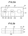
- Fig. 5a is a front view showing a layered body 30 after drying which is manufactured according to another embodiment of the present invention.
- Fig. 5b is a side elevation of the layered body shown in Fig. 5a.
- the green shaped body 31 for the cathode and the green shaped body 32 for the separator are firmly contacted with each other.
- the green shaped bodies 31 and 32 are severally shaped by an extrusion-shaping process and preferably pre-dried.
- the green shaped body 31 is, for example, rectangular in its plan view, and a groove 17A is formed extending along the longitudinal axis thereof.
- the green shaped body 32 has a shape substantially the same as the green shaped body 31, and a groove 18A is formed extending along the longitudinal axis of the rectangle. Two bottom corners of the groove 17A are rounded to a generous radius 14A, and two bottom corners of the groove 18A are rounded to a generous radius 14B, respectively.
- 33A and 33B are joint boundary surfaces of the green shaped bodies 31 and 32. On these joint boundary surfaces, is preferably formed a bond material layer (not shown). Then, the layered body is bound up across its long side with a predetermined number (three in this embodiment) of annular elastic bodies (e.g., rubber band) 34. These elastic bodies 34 are contacted with the top face and both side faces of the green shaped body 31 and both side faces and the bottom face of the green shaped body 32, whereby whole of the layered body 30 is elastically squeezed. In this state, the layered body 30 is sufficiently dried. The drying can be conducted by heating the layered body at a temperature of not exceeding 100°C and/or blasting.
- annular elastic bodies e.g., rubber band
- this layered body 30 is immersed in an elastic material such as a liquid latex or the like, to adhere the elastic material to the layered body and then dried.
- an elastic coating film 35A is formed on the entire exterior surface of the layered body 30, and an elastic coating film 35B is formed on the interior surface of the through-hole 12A.
- this layered body is press-shaped according to a cold isostatic press to manufacture a press-shaped body.
- a conjoint body 36 as shown in Fig. 6b is manufactured by firing this press-shaped body. The firing temperature is appropriately selected according to the kind of the ceramic materials.
- each groove 23A is open at the side face 37c.
- each groove 24A is open at the side face 38c of the separator 38.
- a pair of grooves 23A and 24A facing each other forms an oxidant gas flow passage 22A.
- the boundary surface 33A between the edge banks 37d and 38d and the boundary surface 33B between the intermediate banks 37e and 38e are connected with the oxidant gas flow passage 22A at its flat surfaces parallel with the side faces 37b and 38b, respectively, and not at its each corner portion.
- the side face 37b of the cathode 37 is contiguous to the side face 38b of the separator 38 without difference in level.
- a dense solid electrolyte membrane 19 has its main portion 19a formed on the top face 37a of the cathode 37. Both extended portions 19b cover the side faces 37b of the cathode 37 and further the upper portions of the side faces 38b of the separator 38.
- An anode membrane 20 is formed on the solid electrolyte membrane 19.
- lanthanum strontium manganite powder 100 parts by weight of lanthanum strontium manganite powder were admixed with 3 parts by weight of methyl cellulose and 3 parts by weight of cellulose. To this mixed powder, 14 parts by weight of water were added and kneaded with a kneader. The resultant kneaded product was put into a vacuum pug mill and a round columnar pug shaped body of 50mm diameter and 300mm length for an air electrode was produced.
- lanthanum chromite powder 100 part by weight of lanthanum chromite powder were admixed with 2.5 parts by weight of methyl cellulose and 14 parts by weight of water, and a kneaded product was obtained by using a kneader.
- the resultant kneaded product was put into a vacuum pug mill and a round columnar pug shaped body of 50mm diameter and 300mm length for a separator was produced.
- the shape of the extrusion die was regulated so that every bottom corner of each groove of the shaped body might be rounded to a generous radius.
- the layered body 9A shown in Fig. 2a was manufactured according to the aforementioned process.
- the extrusion rates of both pug shaped bodies were substantially equalized.
- This layered body 9A was put in a thermohygrostatic dryer and dried at 80°C. After drying, the dried layered body was put in an electric furnace, wherein the temperature was increased up to 1,550°C at a temperature increasing rate of 40°C /hr. and kept at 1,550°C for 4 hours to conduct monolithical sintering and the sintered body 21A shown in Fig. 2b was produced.
- This sintered body had dimensions of 7 mm thickness, 21 mm width and 50 mm length.
- the oxidant gas flow passages had a cross-section 3mm high and 3mm wide.
- both A and B as shown in Fig. 2b were 1.5 mm.
- a heat cycle test was conducted. Namely, the temperature of the layered sintered body was increased from room temperature up to 1,200°C at a temperature increasing rate of 200°C /hr., kept at 1,200°C for 30 minutes, decreased from 1,200°C down to 100°C at a temperature decreasing rate of 200°C /hr. and kept at 100°C for 30 minutes. The above temperature rise and fall cycle between 1,200°C and 100°C was repeated and finally the layered sintered body was cooled down to room temperature and examined for crack formation. Ten pieces in total of samples were tested. As the result, even after 20 heat cycles, no crack formation was observed.
- a solid electrolyte membrane and a fuel electrode membrane were formed according to the following process and an electrochemical cell as shown in Fig. 2b was manufactured.
- An yttria-stabilized zirconia membrane 100 ⁇ m thick was formed by flame spraying on the air electrode side of the layered sintered body. Then, this flame-sprayed zirconia membrane was densified by heat-treating at 1,400°C for 3 hours.
- nickel oxide/zirconia mixed powder pasted with polyethylene glycol was screen-printed and fired at 1,400°C for an hour to produce a fuel electrode membrane.
- the electrochemical cell was held by a ceramic manifold, and a nickel mesh was used as a current collector.
- a PyrexTM glass was used for the gas sealing portion between the manifold and electrochemical cell. This PyrexTM glass is melted under power generation conditions at 1,000°C and displays a gas-sealing function.
- As a fuel gas hydrogen gas moistened by bubbling at room temperature was used, and as an oxidant gas, air was used. The air was fed to the air electrode side through the manifold and each oxidant gas flow passage of the electrochemical cell. The hydrogen gas was fed to the fuel electrode side by flowing on the circumference of the electrochemical cell.
- the internal resistance of the electrochemical cell was determined according to a complex impedance method.
- the generating current was made to be 300 mA per unit area of the fuel electrode.
- Each internal resistance at initial stage of power generation and after continuous generation for 100 hours was measured. Change of the internal resistance and whether cracks were formed or not on the electrochemical cell were observed. As the result, even after the continuous generation for 100 hours, neither layer- separation nor crack was observed. Additionally, the initial internal resistance was 0.28 ⁇ ⁇ cm 2 and that after continuous generation for 100 hours was 0.31 ⁇ ⁇ cm 2 .
- Example 2 In the same manner as that of Example 1, a layered sintered body was manufactured. However, the pressure of the each extrusion plunger was adjusted so that the grooves of the electrode might have a depth (A) of 0.5 mm and the grooves of the separator might have a depth (B) of 2.5 mm. As the result, after a 20 times heat cycle test, neither layer separation nor crack was observed. Further, even after the continuous generation for 100 hours, also neither layer separation nor crack was observed. Additionally, the initial internal resistance was 0.30 ⁇ ⁇ cm 2 and that after continuous generation for 100 hours was 0.33 ⁇ ⁇ cm 2 .
- Example 2 In the same manner as that of Example 1, a layered sintered body was manufactured. However, the pressure of the each extrusion plunger was adjusted so that the grooves of the electrode might have a depth (A) of 0.3 mm and the grooves of the separator might have a depth (B) of 2.7 mm. As the result, with respect of one sample, layer separation initiating from near the boundary of the layers was observed after a 20 times heat cycle test. Further, even after a continuous generation for 100 hours, neither layer separation nor crack was observed. Additionally, the initial internal resistance was 0.30 ⁇ ⁇ cm 2 and that after continuous generation for 100 hours was 0.40 ⁇ ⁇ cm 2 .
- Example 2 In the same manner as that of Example 1, a layered sintered body was manufactured. However, the pressure of the each extrusion plunger was adjusted so that the grooves of the electrode might have a depth (A) of 2.0 mm and the grooves of the separator might have a depth (B) of 1.0 mm. As the result, after a 20 times heat cycle test, neither layer separation nor crack was observed. Further, even after the continuous generation for 100 hours, also neither layer separation nor crack was observed. Additionally, the initial internal resistance was 0.27 ⁇ ⁇ cm 2 and that after continuous generation for 100 hours was 0.30 ⁇ ⁇ cm 2 .
- Example 2 In the same manner as that of Example 1, a layered sintered body was manufactured. However, the pressure of the each extrusion plunger was adjusted so that the grooves of the electrode might have a depth (A) of 2.5 mm and the grooves of the separator might have a depth (B) of 0.5 mm. As the result, after a 20 times heat cycle test, neither layer separation nor crack was observed. Further, even after the continuous generation for 100 hours, also neither layer separation nor crack was observed. Additionally, the initial internal resistance was 0.26 ⁇ cm 2 and that after continuous generation for 100 hours was 0.29 ⁇ cm 2 .
- Example 2 In the same manner as that of Example 1, a layered sintered body was manufactured. However, the pressure of the each extrusion plunger was adjusted so that the grooves of the electrode might have a depth (A) of 2.7 7 mm and the grooves of the separator might have a depth (B) of 0.3 mm. As the result, with respect of one sample, layer separation initiating from near the boundary of the layers was observed after a 20 times heat cycle test. Further, even after a continuous generation for 100 hours, neither layer separation nor crack was observed. Additionally, the initial internal resistance was 0.26 ⁇ ⁇ cm 2 and that after continuous generation for 100 hours was 0.36 ⁇ ⁇ cm 2 .
- Example 2 In the same manner as that of Example 1, a layered sintered body was manufactured. However, the pressure of the each extrusion plunger was adjusted so that the grooves of the electrode might have a depth (A) of 3.0 mm and the grooves of the separator might have a depth (B) of 0.0 mm, namely, the separator might be a simple plate. As the result, with respect of 8 samples among 10 samples, layer separation initiating from near the boundary of the layers was observed after a 20 times heat cycle test. Further, after a continuous generation for 100 hours, layer separation from near the boundary of the layers was observed. Additionally, the initial internal resistance was 0.25 ⁇ cm 2 and that after continuous generation for 100 hours was 1.00 ⁇ cm 2 .
- Example 2 In the same manner as that of Example 1, a layered sintered body was manufactured. However, the pressure of the each extrusion plunger was adjusted so that the grooves of the electrode might have a depth (A) of 0.0 mm and the grooves of the separator might have a depth (B) of 3.0 mm, namely, the electrode might be a simple plate. As the result, with respect of 9 samples among 10 samples, layer separation initiating from near the boundary of the layers was observed after a 20 times heat cycle test. Further, after a continuous generation for 100 hours, layer separation from near the boundary of the layers was observed. Additionally, the initial internal resistance was 0.31 ⁇ ⁇ cm 2 and that after continuous generation for 100 hours was 1.41 ⁇ ⁇ cm 2 .
- Example 2 In the same manner as that of Example 1, a layered sintered body was manufactured. However, the layered sintered body had a shape as shown in Fig. 3b. Each oxidant gas flow passage 22B was made to have a diameter of 3.0 mm. The pressure of the each extrusion plunger was adjusted so that the grooves of the electrode might have a depth (A) of 1.5 mm and the grooves of the separator might have a depth (B) of 1.5 mm. As the result, after a 20 times heat cycle test, neither layer separation nor crack was observed. Further, even after the continuous generation for 100 hours, also neither layer- separation nor crack was observed. Additionally, the initial internal resistance was 0.27 ⁇ ⁇ cm 2 and that after continuous generation for 100 hours was 0.28 ⁇ ⁇ cm 2 .
- Pug for air electrode and pug for separator were produced in the same manner as that of Example 1. Then, an electrochemical cell was fabricated according to the process explained with reference to Figs. 5 and 6. However, each shaped body was made to have dimensions of 10 mm thickness, 40 mm width and 100 mm length. These shaped bodies were stacked with interposition therebetween of a paste comprising 50 parts by weight of lanthanum chromite powder, 50 parts by weight of lanthanum manganite powder and some water, dried at 100°C, applied on the surface with a liquid rubber latex and subjected to a hot isostatic press at a load of 4.9 MPa (50 kg/cm 2 ).
- This sintered body was machine finished to provide a layered sintered body having dimensions of 9 mm thickness, 27 mm width and 50 mm length.
- the oxidant gas flow passages had a cross-section 3.0 mm high and 5 mm wide.
- the grooves of the air electrode had a depth (A) of 1.5 mm, and the grooves of the separator also had a depth (B) of 1.5 mm.
- Example 8 In the same manner as that of Example 8, a layered sintered body was manufactured. However, the cross-section of the oxidant gas flow passages was made to have dimensions of 5.0 mm height and 5.0 mm width, and both the depths (A) and (B) were made to be 2.5 mm. As the result, after a 20 times heat cycle test, neither layer separation nor crack was observed. Further, even after the continuous generation for 100 hours, also neither layer separation nor crack was observed. Additionally, the initial internal resistance was 0.31 ⁇ ⁇ cm 2 and that after continuous generation for 100 hours was 0.34 ⁇ ⁇ cm 2 .
- Example 2 In the same manner as that of Example 1, a layered sintered body comprising a cathode of lanthanum manganite and a separator of lanthanum chromite was manufactured. On this layered sintered body, a solid electrolyte membrane and anode membrane were formed according to the following process to provide a water vapor electrolytic cell as shown in Fig. 2b.
- a membrane 60 ⁇ m thick of a 8 mol.% yttria-stabilized zirconia was formed by plasma spray coating on the cathode side of the layered sintered body. Then, this spray coated membrane together with the layered sintered body was heat-treated at 1,400°C for 4 hours in an electric furnace, whereby the spray coated membrane was densified to provide a solid electrolyte membrane.
- a commercially available platinum paste was admixed with a finely powdered 8 mol.% yttria-stabilized zirconia having an average particle diameter of 1 ⁇ m in a proportion of platinum to zirconia of 9 : 1.
- the viscosity of the resulting paste was regulated by adding polyethylene glycol to the mixed powder.
- a membrane of 8 cm 2 in area was formed on the solid electrolyte membrane by means of screen printing process.
- the resultant was fired at 1,300°C for 4 hours in an electric furnace to provide an anode membrane.
- the cell of this example was obtained.
- the cell was once cooled down to room temperature at a temperature decreasing rate of 300°C /min. and then heated again up to 1,000°C at a temperature increasing rate of 300°C /min. The cell was subjected to the 20 times repetition of this cooling-heating cycle. Then, the current density-voltage performance was determined under conditions the same as the above. As the result, the determined current density-voltage performance was substantially the same as that before the cooling-heating cycle. In addition, the cell was taken out after the test and observed. Then, neither layer- separation nor crack was found on the cell.
- a water vapor electrolytic cell was manufactured in the same manner as that of Comparative Example 1. With respect of this cell, the current density-voltage performance was determined in the same manner as Example 10. The result is shown in Table 2. Further with respect of this cell, the cooling-heating cycle was repeated 20 times and then the current density-voltage performance was determined. The result is also shown in Table 2. Voltage (mV) Current Density (mA/cm 2 ) Initial After 20 times cooling-heating cycles 800 0 0 900 48 35 1000 90 61 1100 125 81 1200 176 100 1300 212 120 1500 251 133
- the initial current density-voltage performance was comparable to that of Example 10. However, after conducting the cooling-heating cycle 20 times, the current density was extremely lowered.
Landscapes
- Chemical & Material Sciences (AREA)
- Engineering & Computer Science (AREA)
- Chemical Kinetics & Catalysis (AREA)
- Electrochemistry (AREA)
- Manufacturing & Machinery (AREA)
- General Chemical & Material Sciences (AREA)
- Sustainable Development (AREA)
- Life Sciences & Earth Sciences (AREA)
- Sustainable Energy (AREA)
- Ceramic Engineering (AREA)
- Materials Engineering (AREA)
- Organic Chemistry (AREA)
- Inorganic Chemistry (AREA)
- Metallurgy (AREA)
- Structural Engineering (AREA)
- Analytical Chemistry (AREA)
- Oil, Petroleum & Natural Gas (AREA)
- Fuel Cell (AREA)
- Press-Shaping Or Shaping Using Conveyers (AREA)
Claims (9)
- Gesinterter Schichtkörper für elektrochemische Zellen, bei dem es sich um einen gesinterten Schichtkörper vom planaren Typ handelt, umfassend eine Elektrode (15, 37) und einen darauf geschichteten Separator (16, 38) einer elektrochemischen Zelle, worin eine Vielzahl an Gasströmungsdurchlässen (12, 22) bereitgestellt sind, welcher gesinterte Schichtkörper dadurch gekennzeichnet ist, dass an der Elektrode eine Vielzahl von Nuten (17, 18, 23, 24) an der Seite, die am Separator anliegt, angeordnet ist, dass am Separator eine Vielzahl von Nuten an der Seite, die an der Elektrode anliegt, angeordnet ist, und dass jeder der Gasströmungsdurchlässe durch Koppeln einer der an der Elektrode ausgebildeten Nuten mit jener der am Separator ausgebildeten Nuten, die dieser gegenüberliegt, gebildet ist.
- Gesinterter Schichtkörper nach Anspruch 1, worin die Gasströmungsdurchlässe eine polygonale Querschnittsform aufweisen und jede Ecke der polygonalen Querschnittsform zu einem Radius abgerundet ist.
- Gesinterter Schichtkörper nach Anspruch 1, worin die Gasströmungsdurchlässe eine Querschnittsform aufweisen, die durch einen geschlossenen, abgerundeten Umriss definiert ist.
- Gesinterter Schichtkörper nach einem der Ansprüche 1 bis 3, worin sowohl die in der Elektrode als auch die im Separator bereitgestellten Nuten eine Tiefe von 0,5 bis 10 mm aufweisen.
- Elektrochemische Zelle, umfassend einen gesinterten Schichtkörper vom planaren Typ, umfassend eine Elektrode und einen darauf geschichteten Separator nach einem der Ansprüche 1 bis 4 und weiters umfassend eine auf der Elektrode bereitgestellte Festelektrolytenmembran (19) und eine weitere, auf der Festelektrolytenmembran bereitgestellte Elektrodenmembran (20), welche elektrochemische Zelle dadurch gekennzeichnet ist, dass das Gas in jedem Gasströmungsdurchlass durch den Separator und die Festelektrolytenmembran von äußeren Gasen hermetisch abgedichtet ist.
- Verfahren zur Herstellung eines gesinterten Schichtkörpers (30) mit einer Elektrode und einem darauf geschichteten Separator einer elektrochemischen Zelle,
wobei das Verfahren folgende Schritte umfasst:das kontinuierliche und gleichzeitige Beschicken einer einstückigen Extruderdüse (7, 27) mit Lehm (2, 26A) zur Bildung eines grünen Formkörpers (31) für die Elektrode und mit Lehm (3, 26B) zur Bildung eines grünen Formkörpers (32) für den Separator;das Extrudieren des Lehms aus der Extruderdüse zur Gestalt eines Schichtkörpers, der aus einem grünen Formkörper für die Elektrode und einem grünen Formkörper für den Separator gebildet ist, die paarweise miteinander verbunden sind; und in der Folgedas monolithische Sintern des Schichtkörpers zur Bereitstellung eines gesinterten Körpers mit einer Vielzahl an Gasströmungsdurchlässen, wobei das Verfahren dadurch gekennzeichnet ist, dass eine Vielzahl von Nuten an einer Seite der Elektrode und an einer Seite des Separators bereitgestellt werden, sodass jeder der Gasströmungsdurchlässe durch Koppeln einer der Nuten in der Elektrode mit jener der Nuten des Separators, die dieser gegenüberliegt, gebildet werden. - Verfahren zur Herstellung eines gesinterten Schichtkörpers mit einer Elektrode und einem darauf geschichteten Separator einer elektrochemischen Zelle, wobei das Verfahren folgende Schritte umfasst:das Schichten eines Formkörpers für die Elektrode auf einen Formkörper für den Separator, um einen Schichtkörper bereitzustellen, wobei eine Verbindungsmaterialschicht zwischen der Elektrode und dem Separator auf eine solche Weise eingeschoben ist, dass Durchgangslöcher im Inneren des Schichtkörpers ausgebildet werden, die jeweils einem Gasströmungsdurchlass entsprechen; und daraufhindas monolithische Sintern des Schichtkörpers unter Druck zur Bereitstellung eines gesinterten Schichtkörpers vom planaren Typ, wobei das Verfahren dadurch gekennzeichnet ist, dass eine Vielzahl von Nuten an einer Seite der Elektrode und an einer Seite des Separators bereitgestellt werden, sodass jeder der Gasströmungsdurchlässe durch Koppeln einer der Nuten in der Elektrode mit jener der Nuten des Separators, die dieser gegenüberliegt, gebildet werden.
- Elektrochemische Zelle, umfassend einen gesinterten Schichtkörper nach einem der Ansprüche 1 bis 4.
- Elektrochemische Zelle, umfassend einen durch ein Verfahren nach Anspruch 6 oder 7 hergestellten gesinterten Schichtkörper.
Applications Claiming Priority (6)
| Application Number | Priority Date | Filing Date | Title |
|---|---|---|---|
| JP6718/96 | 1996-01-18 | ||
| JP671896 | 1996-01-18 | ||
| JP671896 | 1996-01-18 | ||
| JP348130/96 | 1996-12-26 | ||
| JP34813096A JP3604848B2 (ja) | 1996-01-18 | 1996-12-26 | 電気化学セル用積層焼結体、電気化学セルおよび電気化学セル用積層焼結体の製造方法 |
| JP34813096 | 1996-12-26 |
Publications (3)
| Publication Number | Publication Date |
|---|---|
| EP0785587A2 EP0785587A2 (de) | 1997-07-23 |
| EP0785587A3 EP0785587A3 (de) | 2000-02-09 |
| EP0785587B1 true EP0785587B1 (de) | 2005-06-22 |
Family
ID=26340915
Family Applications (1)
| Application Number | Title | Priority Date | Filing Date |
|---|---|---|---|
| EP97300239A Expired - Lifetime EP0785587B1 (de) | 1996-01-18 | 1997-01-16 | Gesinterter Mehrschichtkörper für elektrochemische Zelle, elektrochemische Zelle damit und Verfahren ihrer Herstellung |
Country Status (4)
| Country | Link |
|---|---|
| US (2) | US5866275A (de) |
| EP (1) | EP0785587B1 (de) |
| JP (1) | JP3604848B2 (de) |
| DE (1) | DE69733584T2 (de) |
Families Citing this family (25)
| Publication number | Priority date | Publication date | Assignee | Title |
|---|---|---|---|---|
| WO1998021769A1 (fr) * | 1996-11-11 | 1998-05-22 | Gorina, Liliya Fedorovna | Mode de fabrication d'une pile isolee a combustible haute temperature et de ses composants: cathode, anode, passage de courant, couches d'isolation electrique et d'interface, et de l'electrolyte |
| DE59706045D1 (de) * | 1997-08-13 | 2002-02-21 | Siemens Ag | Verfahren zum Herstellen einer isolierenden Komponente für eine Hochtemperatur-Brennstoffzelle und Hochtemperatur-Brennstoffzelle |
| EP0902493B1 (de) * | 1997-09-11 | 2001-01-03 | Sulzer Hexis AG | Elektrochemisch aktives Element zu einer Festoxidbrennstoffzelle |
| DE69905019T2 (de) * | 1998-02-27 | 2003-10-16 | Corning Inc., Corning | Flexible anorganische elektrolytische brennstoffzellenausführung |
| US6458170B1 (en) * | 1998-12-03 | 2002-10-01 | The Regents Of The University Of California | Method for making thin, flat, dense membranes on porous substrates |
| DK174654B1 (da) | 2000-02-02 | 2003-08-11 | Topsoe Haldor As | Faststofoxid brændselscelle og anvendelser heraf |
| EP1344272A2 (de) * | 2000-08-30 | 2003-09-17 | Siemens Aktiengesellschaft | Verfahren zum herstellen einer festkeramischen brennstoffzelle |
| US6916569B2 (en) | 2000-11-23 | 2005-07-12 | Sulzer Hexis Ag | Fuel cell comprising a solid electrolyte layer |
| EP1209753A1 (de) * | 2000-11-23 | 2002-05-29 | Sulzer Hexis AG | Brennstoffzelle mit einer Festelelektrolytschicht |
| JP4252453B2 (ja) * | 2001-09-26 | 2009-04-08 | 日本碍子株式会社 | 電気化学セルおよびその製造方法 |
| YU88103A (sh) * | 2002-05-14 | 2006-08-17 | H.Lundbeck A/S. | Lecenje adhd |
| JP2004362849A (ja) * | 2003-06-03 | 2004-12-24 | Ngk Insulators Ltd | 電気化学セル用基板および電気化学セル |
| AU2004247229B2 (en) * | 2003-06-09 | 2006-12-14 | Saint-Gobain Ceramics & Plastics, Inc. | Fused zirconia-based solid oxide fuel cell |
| US8192888B2 (en) * | 2005-04-19 | 2012-06-05 | Nextech Materials, Ltd. | Two layer electrolyte supported fuel cell stack |
| US7736787B2 (en) * | 2005-09-06 | 2010-06-15 | Nextech Materials, Ltd. | Ceramic membranes with integral seals and support, and electrochemical cells and electrochemical cell stacks including the same |
| JP5105840B2 (ja) * | 2006-11-28 | 2012-12-26 | 京セラ株式会社 | 平板型燃料電池のインターコネクタ及びその製法、平板型燃料電池、平板型燃料電池スタック並びにその製法 |
| US20080318063A1 (en) * | 2007-06-22 | 2008-12-25 | Anderson Jerrel C | Glass laminates with improved weatherability |
| KR100874110B1 (ko) * | 2007-07-20 | 2008-12-15 | 한국과학기술원 | 고체산화물 연료전지용 셀의 연료극 제조방법, 이에 따라제조된 연료극 및 고체산화물 연료전지용 셀 |
| DE102007041513A1 (de) * | 2007-08-31 | 2009-03-05 | Hella Kgaa Hueck & Co. | Anorganische Separatorschicht in Ionen-Akkumulatoren |
| US8790801B2 (en) * | 2007-09-07 | 2014-07-29 | Oerlikon Advanced Technologies Ag | Integrated electrochemical and solar cell |
| TWI463677B (zh) * | 2007-09-07 | 2014-12-01 | Oerlikon Advanced Technologies Ag | 整合式電化學太陽能電池 |
| US7767135B2 (en) * | 2007-10-19 | 2010-08-03 | Corning Incorporated | Method of forming a sintered microfluidic device |
| KR101215418B1 (ko) * | 2011-07-20 | 2012-12-26 | 한국생산기술연구원 | 고체산화물연료전지의 단위셀 제조공정 |
| GB2517928B (en) * | 2013-09-04 | 2018-02-28 | Ceres Ip Co Ltd | Metal supported solid oxide fuel cell |
| JP6608595B2 (ja) * | 2015-02-17 | 2019-11-20 | 日本特殊陶業株式会社 | トンネル付きセラミック部材の製造方法 |
Family Cites Families (14)
| Publication number | Priority date | Publication date | Assignee | Title |
|---|---|---|---|---|
| CS176569B1 (de) * | 1974-07-30 | 1977-06-30 | ||
| US4193860A (en) * | 1978-08-30 | 1980-03-18 | The United States Of America As Represented By The United States Department Of Energy | Liquid-permeable electrode |
| US4339322A (en) * | 1980-04-21 | 1982-07-13 | General Electric Company | Carbon fiber reinforced fluorocarbon-graphite bipolar current collector-separator |
| US4324844A (en) * | 1980-04-28 | 1982-04-13 | Westinghouse Electric Corp. | Variable area fuel cell cooling |
| JPH01292759A (ja) * | 1988-05-19 | 1989-11-27 | Nkk Corp | モノリシック型固体電解質燃料電池 |
| JPH02273465A (ja) * | 1989-04-12 | 1990-11-07 | Nkk Corp | 固体電解質燃料電池の製造方法 |
| US5290642A (en) * | 1990-09-11 | 1994-03-01 | Alliedsignal Aerospace | Method of fabricating a monolithic solid oxide fuel cell |
| US5162167A (en) * | 1990-09-11 | 1992-11-10 | Allied-Signal Inc. | Apparatus and method of fabricating a monolithic solid oxide fuel cell |
| JPH0554897A (ja) * | 1991-08-22 | 1993-03-05 | Mitsubishi Heavy Ind Ltd | 固体電解質セル及びその製造方法 |
| JP2758520B2 (ja) * | 1991-09-27 | 1998-05-28 | 日本碍子株式会社 | 固体電解質型燃料電池の単電池及びこれを用いた発電装置 |
| US5286322A (en) * | 1991-10-18 | 1994-02-15 | Allied-Signal, Inc. | Rapid thermal processing of multilayer tapes for fuel cell applications |
| JPH0668885A (ja) * | 1992-08-21 | 1994-03-11 | Ishikawajima Harima Heavy Ind Co Ltd | 固体電解質型燃料電池の製作方法 |
| GB9305189D0 (en) * | 1993-03-13 | 1993-04-28 | British Nuclear Fuels Plc | Fuel cells |
| US5527363A (en) * | 1993-12-10 | 1996-06-18 | Ballard Power Systems Inc. | Method of fabricating an embossed fluid flow field plate |
-
1996
- 1996-12-26 JP JP34813096A patent/JP3604848B2/ja not_active Expired - Fee Related
-
1997
- 1997-01-14 US US08/783,004 patent/US5866275A/en not_active Expired - Fee Related
- 1997-01-16 EP EP97300239A patent/EP0785587B1/de not_active Expired - Lifetime
- 1997-01-16 DE DE69733584T patent/DE69733584T2/de not_active Expired - Lifetime
-
1998
- 1998-09-15 US US09/153,039 patent/US6179884B1/en not_active Expired - Lifetime
Also Published As
| Publication number | Publication date |
|---|---|
| US6179884B1 (en) | 2001-01-30 |
| US5866275A (en) | 1999-02-02 |
| EP0785587A2 (de) | 1997-07-23 |
| EP0785587A3 (de) | 2000-02-09 |
| DE69733584T2 (de) | 2006-05-11 |
| JPH09259905A (ja) | 1997-10-03 |
| JP3604848B2 (ja) | 2004-12-22 |
| DE69733584D1 (de) | 2005-07-28 |
Similar Documents
| Publication | Publication Date | Title |
|---|---|---|
| EP0785587B1 (de) | Gesinterter Mehrschichtkörper für elektrochemische Zelle, elektrochemische Zelle damit und Verfahren ihrer Herstellung | |
| US6183609B1 (en) | Sintered laminated structures, electrochemical cells and process for producing such sintered laminated structures | |
| US20030148160A1 (en) | Anode-supported tubular solid oxide fuel cell stack and method of fabricating the same | |
| US20070037031A1 (en) | Cermet and ceramic interconnects for a solid oxide fuel cell | |
| US20080246194A1 (en) | Method of producing a ceramic sintered body | |
| DK2701225T3 (en) | Fuel cell and fuel cell stack | |
| JP2003263994A (ja) | 固体電解質型燃料電池 | |
| CN113488689B (zh) | 固体氧化物燃料电池堆及其制备方法 | |
| JP6605969B2 (ja) | 電気化学反応単セル、インターコネクタ−電気化学反応単セル複合体、および、電気化学反応セルスタック | |
| JP3166888B2 (ja) | 固体電解質型燃料電池のスタック | |
| JP4923407B2 (ja) | 固体酸化物形燃料電池の製造方法 | |
| JP2019091584A (ja) | 電気化学反応単セルおよび電気化学反応セルスタック | |
| JP7349847B2 (ja) | 電気化学セル、電気化学反応セルスタック | |
| JP2018006292A (ja) | 電気化学反応単セルの製造方法、および、電気化学反応セルスタックの製造方法 | |
| JP6539179B2 (ja) | 電気化学反応単セルおよび電気化学反応セルスタック | |
| EP3499616B1 (de) | Einzelzelle mit elektrochemischer reaktion und zellstapel mit elektrochemischer reaktion | |
| JP2018032578A (ja) | 電気化学反応セルの製造方法 | |
| JP4010396B2 (ja) | 電気化学装置 | |
| JP2021086786A (ja) | 電気化学反応単セルおよび電気化学反応セルスタック | |
| JPH1064565A (ja) | 固体電解質型燃料電池 | |
| JP7016334B2 (ja) | 電気化学反応単セル、および、電気化学反応セルスタック | |
| JP7132982B2 (ja) | 電気化学反応単セルおよび電気化学反応セルスタック | |
| JPH06111833A (ja) | 固体電解質型燃料電池 | |
| JP4606043B2 (ja) | 固体酸化物形燃料電池及びこれに用いる基板 | |
| JP3681821B2 (ja) | 固体電解質型燃料電池用積層体およびこれを用いた固体電解質型燃料電池 |
Legal Events
| Date | Code | Title | Description |
|---|---|---|---|
| PUAI | Public reference made under article 153(3) epc to a published international application that has entered the european phase |
Free format text: ORIGINAL CODE: 0009012 |
|
| AK | Designated contracting states |
Kind code of ref document: A2 Designated state(s): DE FR GB |
|
| PUAL | Search report despatched |
Free format text: ORIGINAL CODE: 0009013 |
|
| AK | Designated contracting states |
Kind code of ref document: A3 Designated state(s): DE FR GB |
|
| RIC1 | Information provided on ipc code assigned before grant |
Free format text: 7H 01M 8/02 A, 7H 01M 8/12 B, 7C 25B 9/00 B, 7B 01D 53/32 B, 7G 01N 27/419 B, 7H 01M 8/24 B |
|
| 17P | Request for examination filed |
Effective date: 20000508 |
|
| 17Q | First examination report despatched |
Effective date: 20010320 |
|
| GRAP | Despatch of communication of intention to grant a patent |
Free format text: ORIGINAL CODE: EPIDOSNIGR1 |
|
| GRAS | Grant fee paid |
Free format text: ORIGINAL CODE: EPIDOSNIGR3 |
|
| GRAA | (expected) grant |
Free format text: ORIGINAL CODE: 0009210 |
|
| AK | Designated contracting states |
Kind code of ref document: B1 Designated state(s): DE FR GB |
|
| REG | Reference to a national code |
Ref country code: GB Ref legal event code: FG4D |
|
| REF | Corresponds to: |
Ref document number: 69733584 Country of ref document: DE Date of ref document: 20050728 Kind code of ref document: P |
|
| ET | Fr: translation filed | ||
| PLBE | No opposition filed within time limit |
Free format text: ORIGINAL CODE: 0009261 |
|
| STAA | Information on the status of an ep patent application or granted ep patent |
Free format text: STATUS: NO OPPOSITION FILED WITHIN TIME LIMIT |
|
| 26N | No opposition filed |
Effective date: 20060323 |
|
| PGFP | Annual fee paid to national office [announced via postgrant information from national office to epo] |
Ref country code: DE Payment date: 20140108 Year of fee payment: 18 |
|
| PGFP | Annual fee paid to national office [announced via postgrant information from national office to epo] |
Ref country code: FR Payment date: 20140108 Year of fee payment: 18 |
|
| PGFP | Annual fee paid to national office [announced via postgrant information from national office to epo] |
Ref country code: GB Payment date: 20140115 Year of fee payment: 18 |
|
| REG | Reference to a national code |
Ref country code: DE Ref legal event code: R119 Ref document number: 69733584 Country of ref document: DE |
|
| GBPC | Gb: european patent ceased through non-payment of renewal fee |
Effective date: 20150116 |
|
| PG25 | Lapsed in a contracting state [announced via postgrant information from national office to epo] |
Ref country code: GB Free format text: LAPSE BECAUSE OF NON-PAYMENT OF DUE FEES Effective date: 20150116 Ref country code: DE Free format text: LAPSE BECAUSE OF NON-PAYMENT OF DUE FEES Effective date: 20150801 |
|
| REG | Reference to a national code |
Ref country code: FR Ref legal event code: ST Effective date: 20150930 |
|
| PG25 | Lapsed in a contracting state [announced via postgrant information from national office to epo] |
Ref country code: FR Free format text: LAPSE BECAUSE OF NON-PAYMENT OF DUE FEES Effective date: 20150202 |