EP0782941B1 - Procédé et dispositif pour régler la répartition de la puissance électrique dans un véhicule automobile, notamment à propulsion hybride - Google Patents
Procédé et dispositif pour régler la répartition de la puissance électrique dans un véhicule automobile, notamment à propulsion hybride Download PDFInfo
- Publication number
- EP0782941B1 EP0782941B1 EP96120329A EP96120329A EP0782941B1 EP 0782941 B1 EP0782941 B1 EP 0782941B1 EP 96120329 A EP96120329 A EP 96120329A EP 96120329 A EP96120329 A EP 96120329A EP 0782941 B1 EP0782941 B1 EP 0782941B1
- Authority
- EP
- European Patent Office
- Prior art keywords
- power
- battery
- voltage
- supply circuit
- electric
- Prior art date
- Legal status (The legal status is an assumption and is not a legal conclusion. Google has not performed a legal analysis and makes no representation as to the accuracy of the status listed.)
- Expired - Lifetime
Links
Images


Classifications
-
- B—PERFORMING OPERATIONS; TRANSPORTING
- B60—VEHICLES IN GENERAL
- B60W—CONJOINT CONTROL OF VEHICLE SUB-UNITS OF DIFFERENT TYPE OR DIFFERENT FUNCTION; CONTROL SYSTEMS SPECIALLY ADAPTED FOR HYBRID VEHICLES; ROAD VEHICLE DRIVE CONTROL SYSTEMS FOR PURPOSES NOT RELATED TO THE CONTROL OF A PARTICULAR SUB-UNIT
- B60W10/00—Conjoint control of vehicle sub-units of different type or different function
- B60W10/24—Conjoint control of vehicle sub-units of different type or different function including control of energy storage means
- B60W10/26—Conjoint control of vehicle sub-units of different type or different function including control of energy storage means for electrical energy, e.g. batteries or capacitors
-
- B—PERFORMING OPERATIONS; TRANSPORTING
- B60—VEHICLES IN GENERAL
- B60K—ARRANGEMENT OR MOUNTING OF PROPULSION UNITS OR OF TRANSMISSIONS IN VEHICLES; ARRANGEMENT OR MOUNTING OF PLURAL DIVERSE PRIME-MOVERS IN VEHICLES; AUXILIARY DRIVES FOR VEHICLES; INSTRUMENTATION OR DASHBOARDS FOR VEHICLES; ARRANGEMENTS IN CONNECTION WITH COOLING, AIR INTAKE, GAS EXHAUST OR FUEL SUPPLY OF PROPULSION UNITS IN VEHICLES
- B60K6/00—Arrangement or mounting of plural diverse prime-movers for mutual or common propulsion, e.g. hybrid propulsion systems comprising electric motors and internal combustion engines ; Control systems therefor, i.e. systems controlling two or more prime movers, or controlling one of these prime movers and any of the transmission, drive or drive units Informative references: mechanical gearings with secondary electric drive F16H3/72; arrangements for handling mechanical energy structurally associated with the dynamo-electric machine H02K7/00; machines comprising structurally interrelated motor and generator parts H02K51/00; dynamo-electric machines not otherwise provided for in H02K see H02K99/00
- B60K6/20—Arrangement or mounting of plural diverse prime-movers for mutual or common propulsion, e.g. hybrid propulsion systems comprising electric motors and internal combustion engines ; Control systems therefor, i.e. systems controlling two or more prime movers, or controlling one of these prime movers and any of the transmission, drive or drive units Informative references: mechanical gearings with secondary electric drive F16H3/72; arrangements for handling mechanical energy structurally associated with the dynamo-electric machine H02K7/00; machines comprising structurally interrelated motor and generator parts H02K51/00; dynamo-electric machines not otherwise provided for in H02K see H02K99/00 the prime-movers consisting of electric motors and internal combustion engines, e.g. HEVs
- B60K6/42—Arrangement or mounting of plural diverse prime-movers for mutual or common propulsion, e.g. hybrid propulsion systems comprising electric motors and internal combustion engines ; Control systems therefor, i.e. systems controlling two or more prime movers, or controlling one of these prime movers and any of the transmission, drive or drive units Informative references: mechanical gearings with secondary electric drive F16H3/72; arrangements for handling mechanical energy structurally associated with the dynamo-electric machine H02K7/00; machines comprising structurally interrelated motor and generator parts H02K51/00; dynamo-electric machines not otherwise provided for in H02K see H02K99/00 the prime-movers consisting of electric motors and internal combustion engines, e.g. HEVs characterised by the architecture of the hybrid electric vehicle
- B60K6/46—Series type
-
- B—PERFORMING OPERATIONS; TRANSPORTING
- B60—VEHICLES IN GENERAL
- B60L—PROPULSION OF ELECTRICALLY-PROPELLED VEHICLES; SUPPLYING ELECTRIC POWER FOR AUXILIARY EQUIPMENT OF ELECTRICALLY-PROPELLED VEHICLES; ELECTRODYNAMIC BRAKE SYSTEMS FOR VEHICLES IN GENERAL; MAGNETIC SUSPENSION OR LEVITATION FOR VEHICLES; MONITORING OPERATING VARIABLES OF ELECTRICALLY-PROPELLED VEHICLES; ELECTRIC SAFETY DEVICES FOR ELECTRICALLY-PROPELLED VEHICLES
- B60L15/00—Methods, circuits, or devices for controlling the traction-motor speed of electrically-propelled vehicles
- B60L15/20—Methods, circuits, or devices for controlling the traction-motor speed of electrically-propelled vehicles for control of the vehicle or its driving motor to achieve a desired performance, e.g. speed, torque, programmed variation of speed
- B60L15/2045—Methods, circuits, or devices for controlling the traction-motor speed of electrically-propelled vehicles for control of the vehicle or its driving motor to achieve a desired performance, e.g. speed, torque, programmed variation of speed for optimising the use of energy
-
- B—PERFORMING OPERATIONS; TRANSPORTING
- B60—VEHICLES IN GENERAL
- B60L—PROPULSION OF ELECTRICALLY-PROPELLED VEHICLES; SUPPLYING ELECTRIC POWER FOR AUXILIARY EQUIPMENT OF ELECTRICALLY-PROPELLED VEHICLES; ELECTRODYNAMIC BRAKE SYSTEMS FOR VEHICLES IN GENERAL; MAGNETIC SUSPENSION OR LEVITATION FOR VEHICLES; MONITORING OPERATING VARIABLES OF ELECTRICALLY-PROPELLED VEHICLES; ELECTRIC SAFETY DEVICES FOR ELECTRICALLY-PROPELLED VEHICLES
- B60L50/00—Electric propulsion with power supplied within the vehicle
- B60L50/10—Electric propulsion with power supplied within the vehicle using propulsion power supplied by engine-driven generators, e.g. generators driven by combustion engines
- B60L50/13—Electric propulsion with power supplied within the vehicle using propulsion power supplied by engine-driven generators, e.g. generators driven by combustion engines using AC generators and AC motors
-
- B—PERFORMING OPERATIONS; TRANSPORTING
- B60—VEHICLES IN GENERAL
- B60L—PROPULSION OF ELECTRICALLY-PROPELLED VEHICLES; SUPPLYING ELECTRIC POWER FOR AUXILIARY EQUIPMENT OF ELECTRICALLY-PROPELLED VEHICLES; ELECTRODYNAMIC BRAKE SYSTEMS FOR VEHICLES IN GENERAL; MAGNETIC SUSPENSION OR LEVITATION FOR VEHICLES; MONITORING OPERATING VARIABLES OF ELECTRICALLY-PROPELLED VEHICLES; ELECTRIC SAFETY DEVICES FOR ELECTRICALLY-PROPELLED VEHICLES
- B60L50/00—Electric propulsion with power supplied within the vehicle
- B60L50/50—Electric propulsion with power supplied within the vehicle using propulsion power supplied by batteries or fuel cells
- B60L50/51—Electric propulsion with power supplied within the vehicle using propulsion power supplied by batteries or fuel cells characterised by AC-motors
-
- B—PERFORMING OPERATIONS; TRANSPORTING
- B60—VEHICLES IN GENERAL
- B60L—PROPULSION OF ELECTRICALLY-PROPELLED VEHICLES; SUPPLYING ELECTRIC POWER FOR AUXILIARY EQUIPMENT OF ELECTRICALLY-PROPELLED VEHICLES; ELECTRODYNAMIC BRAKE SYSTEMS FOR VEHICLES IN GENERAL; MAGNETIC SUSPENSION OR LEVITATION FOR VEHICLES; MONITORING OPERATING VARIABLES OF ELECTRICALLY-PROPELLED VEHICLES; ELECTRIC SAFETY DEVICES FOR ELECTRICALLY-PROPELLED VEHICLES
- B60L50/00—Electric propulsion with power supplied within the vehicle
- B60L50/50—Electric propulsion with power supplied within the vehicle using propulsion power supplied by batteries or fuel cells
- B60L50/60—Electric propulsion with power supplied within the vehicle using propulsion power supplied by batteries or fuel cells using power supplied by batteries
- B60L50/61—Electric propulsion with power supplied within the vehicle using propulsion power supplied by batteries or fuel cells using power supplied by batteries by batteries charged by engine-driven generators, e.g. series hybrid electric vehicles
-
- B—PERFORMING OPERATIONS; TRANSPORTING
- B60—VEHICLES IN GENERAL
- B60L—PROPULSION OF ELECTRICALLY-PROPELLED VEHICLES; SUPPLYING ELECTRIC POWER FOR AUXILIARY EQUIPMENT OF ELECTRICALLY-PROPELLED VEHICLES; ELECTRODYNAMIC BRAKE SYSTEMS FOR VEHICLES IN GENERAL; MAGNETIC SUSPENSION OR LEVITATION FOR VEHICLES; MONITORING OPERATING VARIABLES OF ELECTRICALLY-PROPELLED VEHICLES; ELECTRIC SAFETY DEVICES FOR ELECTRICALLY-PROPELLED VEHICLES
- B60L58/00—Methods or circuit arrangements for monitoring or controlling batteries or fuel cells, specially adapted for electric vehicles
- B60L58/10—Methods or circuit arrangements for monitoring or controlling batteries or fuel cells, specially adapted for electric vehicles for monitoring or controlling batteries
- B60L58/12—Methods or circuit arrangements for monitoring or controlling batteries or fuel cells, specially adapted for electric vehicles for monitoring or controlling batteries responding to state of charge [SoC]
-
- B—PERFORMING OPERATIONS; TRANSPORTING
- B60—VEHICLES IN GENERAL
- B60L—PROPULSION OF ELECTRICALLY-PROPELLED VEHICLES; SUPPLYING ELECTRIC POWER FOR AUXILIARY EQUIPMENT OF ELECTRICALLY-PROPELLED VEHICLES; ELECTRODYNAMIC BRAKE SYSTEMS FOR VEHICLES IN GENERAL; MAGNETIC SUSPENSION OR LEVITATION FOR VEHICLES; MONITORING OPERATING VARIABLES OF ELECTRICALLY-PROPELLED VEHICLES; ELECTRIC SAFETY DEVICES FOR ELECTRICALLY-PROPELLED VEHICLES
- B60L2200/00—Type of vehicles
- B60L2200/26—Rail vehicles
-
- B—PERFORMING OPERATIONS; TRANSPORTING
- B60—VEHICLES IN GENERAL
- B60L—PROPULSION OF ELECTRICALLY-PROPELLED VEHICLES; SUPPLYING ELECTRIC POWER FOR AUXILIARY EQUIPMENT OF ELECTRICALLY-PROPELLED VEHICLES; ELECTRODYNAMIC BRAKE SYSTEMS FOR VEHICLES IN GENERAL; MAGNETIC SUSPENSION OR LEVITATION FOR VEHICLES; MONITORING OPERATING VARIABLES OF ELECTRICALLY-PROPELLED VEHICLES; ELECTRIC SAFETY DEVICES FOR ELECTRICALLY-PROPELLED VEHICLES
- B60L2210/00—Converter types
- B60L2210/30—AC to DC converters
-
- B—PERFORMING OPERATIONS; TRANSPORTING
- B60—VEHICLES IN GENERAL
- B60L—PROPULSION OF ELECTRICALLY-PROPELLED VEHICLES; SUPPLYING ELECTRIC POWER FOR AUXILIARY EQUIPMENT OF ELECTRICALLY-PROPELLED VEHICLES; ELECTRODYNAMIC BRAKE SYSTEMS FOR VEHICLES IN GENERAL; MAGNETIC SUSPENSION OR LEVITATION FOR VEHICLES; MONITORING OPERATING VARIABLES OF ELECTRICALLY-PROPELLED VEHICLES; ELECTRIC SAFETY DEVICES FOR ELECTRICALLY-PROPELLED VEHICLES
- B60L2240/00—Control parameters of input or output; Target parameters
- B60L2240/40—Drive Train control parameters
- B60L2240/42—Drive Train control parameters related to electric machines
- B60L2240/421—Speed
-
- B—PERFORMING OPERATIONS; TRANSPORTING
- B60—VEHICLES IN GENERAL
- B60L—PROPULSION OF ELECTRICALLY-PROPELLED VEHICLES; SUPPLYING ELECTRIC POWER FOR AUXILIARY EQUIPMENT OF ELECTRICALLY-PROPELLED VEHICLES; ELECTRODYNAMIC BRAKE SYSTEMS FOR VEHICLES IN GENERAL; MAGNETIC SUSPENSION OR LEVITATION FOR VEHICLES; MONITORING OPERATING VARIABLES OF ELECTRICALLY-PROPELLED VEHICLES; ELECTRIC SAFETY DEVICES FOR ELECTRICALLY-PROPELLED VEHICLES
- B60L2240/00—Control parameters of input or output; Target parameters
- B60L2240/40—Drive Train control parameters
- B60L2240/52—Drive Train control parameters related to converters
- B60L2240/527—Voltage
-
- B—PERFORMING OPERATIONS; TRANSPORTING
- B60—VEHICLES IN GENERAL
- B60L—PROPULSION OF ELECTRICALLY-PROPELLED VEHICLES; SUPPLYING ELECTRIC POWER FOR AUXILIARY EQUIPMENT OF ELECTRICALLY-PROPELLED VEHICLES; ELECTRODYNAMIC BRAKE SYSTEMS FOR VEHICLES IN GENERAL; MAGNETIC SUSPENSION OR LEVITATION FOR VEHICLES; MONITORING OPERATING VARIABLES OF ELECTRICALLY-PROPELLED VEHICLES; ELECTRIC SAFETY DEVICES FOR ELECTRICALLY-PROPELLED VEHICLES
- B60L2250/00—Driver interactions
- B60L2250/26—Driver interactions by pedal actuation
-
- B—PERFORMING OPERATIONS; TRANSPORTING
- B60—VEHICLES IN GENERAL
- B60W—CONJOINT CONTROL OF VEHICLE SUB-UNITS OF DIFFERENT TYPE OR DIFFERENT FUNCTION; CONTROL SYSTEMS SPECIALLY ADAPTED FOR HYBRID VEHICLES; ROAD VEHICLE DRIVE CONTROL SYSTEMS FOR PURPOSES NOT RELATED TO THE CONTROL OF A PARTICULAR SUB-UNIT
- B60W2710/00—Output or target parameters relating to a particular sub-units
- B60W2710/08—Electric propulsion units
- B60W2710/086—Power
-
- Y—GENERAL TAGGING OF NEW TECHNOLOGICAL DEVELOPMENTS; GENERAL TAGGING OF CROSS-SECTIONAL TECHNOLOGIES SPANNING OVER SEVERAL SECTIONS OF THE IPC; TECHNICAL SUBJECTS COVERED BY FORMER USPC CROSS-REFERENCE ART COLLECTIONS [XRACs] AND DIGESTS
- Y02—TECHNOLOGIES OR APPLICATIONS FOR MITIGATION OR ADAPTATION AGAINST CLIMATE CHANGE
- Y02T—CLIMATE CHANGE MITIGATION TECHNOLOGIES RELATED TO TRANSPORTATION
- Y02T10/00—Road transport of goods or passengers
- Y02T10/60—Other road transportation technologies with climate change mitigation effect
- Y02T10/62—Hybrid vehicles
-
- Y—GENERAL TAGGING OF NEW TECHNOLOGICAL DEVELOPMENTS; GENERAL TAGGING OF CROSS-SECTIONAL TECHNOLOGIES SPANNING OVER SEVERAL SECTIONS OF THE IPC; TECHNICAL SUBJECTS COVERED BY FORMER USPC CROSS-REFERENCE ART COLLECTIONS [XRACs] AND DIGESTS
- Y02—TECHNOLOGIES OR APPLICATIONS FOR MITIGATION OR ADAPTATION AGAINST CLIMATE CHANGE
- Y02T—CLIMATE CHANGE MITIGATION TECHNOLOGIES RELATED TO TRANSPORTATION
- Y02T10/00—Road transport of goods or passengers
- Y02T10/60—Other road transportation technologies with climate change mitigation effect
- Y02T10/64—Electric machine technologies in electromobility
-
- Y—GENERAL TAGGING OF NEW TECHNOLOGICAL DEVELOPMENTS; GENERAL TAGGING OF CROSS-SECTIONAL TECHNOLOGIES SPANNING OVER SEVERAL SECTIONS OF THE IPC; TECHNICAL SUBJECTS COVERED BY FORMER USPC CROSS-REFERENCE ART COLLECTIONS [XRACs] AND DIGESTS
- Y02—TECHNOLOGIES OR APPLICATIONS FOR MITIGATION OR ADAPTATION AGAINST CLIMATE CHANGE
- Y02T—CLIMATE CHANGE MITIGATION TECHNOLOGIES RELATED TO TRANSPORTATION
- Y02T10/00—Road transport of goods or passengers
- Y02T10/60—Other road transportation technologies with climate change mitigation effect
- Y02T10/70—Energy storage systems for electromobility, e.g. batteries
-
- Y—GENERAL TAGGING OF NEW TECHNOLOGICAL DEVELOPMENTS; GENERAL TAGGING OF CROSS-SECTIONAL TECHNOLOGIES SPANNING OVER SEVERAL SECTIONS OF THE IPC; TECHNICAL SUBJECTS COVERED BY FORMER USPC CROSS-REFERENCE ART COLLECTIONS [XRACs] AND DIGESTS
- Y02—TECHNOLOGIES OR APPLICATIONS FOR MITIGATION OR ADAPTATION AGAINST CLIMATE CHANGE
- Y02T—CLIMATE CHANGE MITIGATION TECHNOLOGIES RELATED TO TRANSPORTATION
- Y02T10/00—Road transport of goods or passengers
- Y02T10/60—Other road transportation technologies with climate change mitigation effect
- Y02T10/7072—Electromobility specific charging systems or methods for batteries, ultracapacitors, supercapacitors or double-layer capacitors
-
- Y—GENERAL TAGGING OF NEW TECHNOLOGICAL DEVELOPMENTS; GENERAL TAGGING OF CROSS-SECTIONAL TECHNOLOGIES SPANNING OVER SEVERAL SECTIONS OF THE IPC; TECHNICAL SUBJECTS COVERED BY FORMER USPC CROSS-REFERENCE ART COLLECTIONS [XRACs] AND DIGESTS
- Y02—TECHNOLOGIES OR APPLICATIONS FOR MITIGATION OR ADAPTATION AGAINST CLIMATE CHANGE
- Y02T—CLIMATE CHANGE MITIGATION TECHNOLOGIES RELATED TO TRANSPORTATION
- Y02T10/00—Road transport of goods or passengers
- Y02T10/60—Other road transportation technologies with climate change mitigation effect
- Y02T10/72—Electric energy management in electromobility
-
- Y—GENERAL TAGGING OF NEW TECHNOLOGICAL DEVELOPMENTS; GENERAL TAGGING OF CROSS-SECTIONAL TECHNOLOGIES SPANNING OVER SEVERAL SECTIONS OF THE IPC; TECHNICAL SUBJECTS COVERED BY FORMER USPC CROSS-REFERENCE ART COLLECTIONS [XRACs] AND DIGESTS
- Y10—TECHNICAL SUBJECTS COVERED BY FORMER USPC
- Y10S—TECHNICAL SUBJECTS COVERED BY FORMER USPC CROSS-REFERENCE ART COLLECTIONS [XRACs] AND DIGESTS
- Y10S903/00—Hybrid electric vehicles, HEVS
- Y10S903/902—Prime movers comprising electrical and internal combustion motors
- Y10S903/903—Prime movers comprising electrical and internal combustion motors having energy storing means, e.g. battery, capacitor
Definitions
- the present invention relates to a method for adjusting the distribution of electrical power in a circuit DC power supply in a vehicle automobile with several electrical components likely to consume and / or produce power on the supply circuit, one of said members electric being an electric power unit likely to cause at least one drive wheel of the vehicle.
- the invention also relates to a system likely to apply such a process.
- the invention applies in particular to vehicles with hybrid propulsion of the series type, provided with a group generator which includes a heat engine driving a electric generator, but it is also applicable to vehicles with parallel or mixed hybrid propulsion series-parallel, as well as purely vehicles where the electrical energy required for the traction is provided by a source other than a group generator, for example a storage battery, a fuel cell or photovoltaic cells.
- a source other than a group generator for example a storage battery, a fuel cell or photovoltaic cells.
- a hybrid powered motor vehicle of the type series includes a generator group with thermal engine coupled to an electric generator, which provides electricity to a power circuit, usually to direct voltage so that a storage battery can be connected to this circuit.
- a propellant assembly having one or more electric motors is powered by the power circuit to drive the driving wheels of the vehicle.
- the thruster assembly can also perform electric regenerative braking, thus providing electrical power to the power circuit.
- This energy can be consumed by other connected devices to the power circuit, for example it can be stored in chemical form in a battery accumulators, or be stored in an accumulator kinetic energy, or be dissipated thermally in a safety device intended to absorb a possible excess energy.
- the traditional method for managing the flow of power uses exact knowledge of powers produced and consumed by all elements of the system. This method requires calculating what is the power that each organ must produce or consume in order to balance the circuit. We must then know precisely the method of adjusting each component of the system to achieve correct adjustment of all. Even if an organ consumes a power which is not important in the functioning of the system, it is necessary to know it, and this in a way precise. Consequently, the application of this method to manage a system where N organs are connected to the supply circuit requires the use of at least N-1 current sensors. These sensors do not offer generally not good accuracy over a wide range which introduces margins of error into the setting and often requires additional settings to provide stability. When a battery is connected to the power circuit it may be necessary to him prioritize in the tuning process, because that it does not tolerate fluctuations very well common, it is fragile and relatively expensive. The implementation of such priority in the process adjustment represents an additional complication.
- document EP-A-0 543 390 describes a vehicle drive control device hybrid series provided with a generator group comprising a internal combustion engine and generator connected to the supply circuit.
- This circuit supplies a powertrain that includes a DC / AC converter and a three-phase electric motor.
- This engine drives two drive wheels via a differential.
- a battery directly connected to the power circuit allows three modes of powering the powertrain depending on the power demanded of it, namely battery only power within a range low power, power only from the generator group in a medium power range, corresponding to a range of good engine efficiency thermal, and the supply by the generator group and the battery in a high power range.
- the regulation of the whole is ensured by a unit electronics which receives the setpoint signals from the conductor and signals representing the state of the system, namely the current produced by the current generator continuous, the current entering or leaving the battery, the supply circuit voltage and motor speed electric. Based on this information, the unit of regulation determines the different power flows in acting on the fuel supply of the engine thermal, on the generator excitation current to obtain a determined circuit voltage power supply, and on the DC / AC converter the propellant assembly. So she orders at the same time the electrical power produced by the generator set and the electrical power consumed by the whole propellant, and it adjusts the balance of the three flows of power concerned by monitoring two of them, at battery terminals and to the output terminals of the generator.
- the present invention aims to avoid the aforementioned drawbacks of the art previous, thanks to a method for adjusting the flow of power between the different elements of the system in a simple, reliable and economical, advantageously applying to different configurations of the drive system, in particular with or without battery, and with or without organ system connected to the supply circuit, without requiring radical changes basic settings for switching from one system to another. Another goal is to obtain a stable and reliable adjustment of the system, in particular by avoiding as much as possible the use of current sensors.
- Another object is to be able to control the operation of a battery by avoiding ripples of the current across its terminals, in order to increase its lifetime.
- the process should offer maximum flexibility in adjusting the flow of power, i.e. allowing a wide range of combinations to achieve optimal system performance, as well as attractive ergonomics vehicle.
- the invention relates to a process of the kind indicated in the preamble, characterized in that in a traction mode, the propellant assembly is defined as a power balancing member, which exchanges a regulated power with the supply circuit, a circuit setpoint voltage is determined supply, an effective circuit voltage is continuously monitored power supply and regulating said regulated power of the balancing member of so as to maintain said effective voltage at said setpoint voltage.
- One of said electrical components can be a generator group capable of to exchange on command a first power with the supply circuit.
- control means can determine said first power to be supplied by the generator group essentially on demand of power or torque given by the driver, without having to adjust this real-time power based on the distribution of power flows electric in the supply circuit.
- the adjustment to be made by a unit electronics consists essentially in monitoring the voltage of the supply circuit, which will increase if consumption is insufficient or decrease if the consumption is too high, compare this effective voltage to a value of setpoint and, in case of deviation, to adjust the power of the balancing device so to bring the voltage back to the set value. In traction mode, it's easy make this adjustment on the thruster assembly, because this is often the main consumer and in most cases includes a converter DC / AC with wide adjustment possibilities.
- the choice of the supply circuit voltage as an essential parameter adjustment is advantageous for several reasons. This is a common parameter for all the organs connected to the circuit, whatever the number and nature of these. This voltage varies in a small range and can be measured accurately.
- the control unit defines the setpoint voltage in function of a desired distribution of power flows, and then the adjustment can be made without measuring these flow, so without using current sensors.
- the voltage-based setting is especially advantageous because the set voltage can be chosen according to the characteristics of the battery and in particular its state of charge, and this choice allows to predetermine the power drawn from the battery or absorbed by it. It allows in particular to easily stabilize the current across the battery a zero value, as will be explained later.
- the method according to the invention also has the advantage of apply in the same way, if necessary, to the mode of electric braking only in traction mode, also with different configurations of the drive system.
- document EP-A-0 645 278 describes a method for controlling a series hybrid vehicle having a buffer battery connected to the supply circuit, where an electronic control unit monitors the voltage and the state of charge of the battery to manage the flows of electric power.
- adjustment by this process is much less simple and stable than that of the present invention, because it requires calculating the effective power of the power unit from measurements of its torque and speed, or of the current and of the voltage of the electric motor and then to feed back on the generator set according to this power and the state of charge of the battery to keep it between certain limits. It is therefore the battery which ensures precise balance of power flows, undergoing almost constantly charge and discharge cycles.
- the present invention also relates to a drive system for motor vehicle, in particular for implementing the method according to the invention, said system comprising several electrical members capable of consume and / or produce power on the supply circuit, one of said organs being an adjustable electric propellant assembly capable of driving at least one driving wheel of the vehicle, and control means arranged to control the power of the power unit, which exchanges a second power with the supply circuit, the control means being arranged to continuously monitor the effective voltage of the supply circuit, characterized in that the control means comprise an electronic unit adjuster associated with the propellant assembly and arranged to adjust the power of the latter in a traction mode on the basis of a defined reference voltage by the control means, so as to maintain said effective voltage at level of said set voltage.
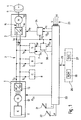
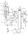
- the example described here relates to the drive system of a motor vehicle with hybrid propulsion of the series type, comprising a generator group 1 arranged to deliver a direct electric current I G with direct voltage U 0 on a two-wire supply circuit 2.
- This circuit supplies a propellant assembly 3 which drives at least one driving wheel 4 of the vehicle by a shaft 5 or by means of any other mechanical transmission means.
- the vehicle generally comprises several driving wheels, driven either by a common electric motor, or by individual electric motors.
- the circuit power supply 2 is also connected to a battery accumulators 6 serving as a buffer, to a safety 7 designed to absorb power excess, and to one or more other organs consumers 8 for example a heater and of air conditioning of the passenger compartment of the vehicle.
- a battery accumulators 6 serving as a buffer
- a safety 7 designed to absorb power excess
- one or more other organs consumers 8 for example a heater and of air conditioning of the passenger compartment of the vehicle.
- the generator group 1 comprises in known manner a heat engine 11, for example of the Otto, Diesel or gas turbine type, driving a three-phase generator 12, for example of the asynchronous or brushless type, and a AC / DC converter 13 which delivers the direct current I G to the supply circuit 2.
- the generator group 1 could comprise a direct current generator or be constituted by any other on-board source with adjustable power, such as '' a fuel cell, photovoltaic cells associated with a DC / DC converter, etc.
- the propellant assembly 3 shown diagrammatically at Figure 1 includes an electronic DC / AC converter 14 which is coupled by a three-phase network 15 to one or several electric machines 16, for example of the type asynchronous or brushless.
- each machine electric 16 is coupled to a single driving wheel 4 by its shaft 5, and it can work as well in engine for traction than in generator for braking electric with recovery, then providing power to supply circuit 2 through the common converter 14.
- the functioning of the training system is managed by an electronic control unit 20 depending on the state of the system and according to the commands given by the conductor, which are shown schematically here by an accelerator pedal 21 delivering a command to traction T and a brake pedal 22 delivering a electric brake control F.
- the control signals T and F each have a variable amplitude representing a performance desired by the driver.
- the two signals T and F could come from the same pedal.
- the control unit 20 receives signals delivered by sensors which are not shown, in order to simplify the presentation.
- the main of these signals represents the effective voltage U0 of the supply circuit 2, i.e. the quantity which plays the essential role in the process according to the invention.
- the other status signals 23 received by the unit 20 are shown schematically in the figure by a signal V, indicating the speed of the shaft 5 of the electric traction machine 16, and a group of signals X capable indicate, for example, the presence of the safety device 7, the engaged state or triggered from consumer 8, etc.
- unit 20 controls the system driven by at least two setpoint signals PGc and U0c.
- the PGc signal continuously indicates to generator group 1 the electrical power it must supply to the supply circuit 2.
- group 1 comprises a electronic management unit which regulates the power output of the group, in particular the IG current, acting in this case on the air supply and in fuel from the engine 11 and on the generator 12 to adjust its resisting torque.
- the signal U0c acts only on the power unit 3. In the present example, it is transmitted to an electronic adjustment unit 24 which also receives the signal representative of the effective voltage U0 of the circuit 2.
- the adjustment unit 24 compares the value U0 with the value U0c and, according to the result of this comparison, set the traction converter 14 to by means of an ST signal which corresponds to an increase or decrease in electrical power of converter 14, therefore also to a variation of the mechanical power of the electric machine 16 operating as a motor or generator.
- the adjustment of the converter 14 can vary the voltage, the current and / or the supply frequency on the three-phase network 15.
- control unit 20 can also deliver a braking torque setpoint F c to the adjustment unit 24 to modify the action accordingly. of the propulsion unit 3, as will be described later.
- the unit 20 can control this member by means of a signal S c , as will be described below.
- control unit 20 is associated or combined with a battery management unit 26 comprising in particular a block 27, which monitors the state of charge (SOC) from battery 6 and provides a corresponding signal, and a block 28 such as a read only memory (ROM) or a device with fuzzy logic, which contains characteristic data of this battery.
- a battery management unit 26 comprising in particular a block 27, which monitors the state of charge (SOC) from battery 6 and provides a corresponding signal
- SOC state of charge
- ROM read only memory
- fuzzy logic which contains characteristic data of this battery.
- a current measurement is preferably avoided in the process according to the invention, it is not excluded in all cases and can be used in particular for security checks or to calculate the state of battery charge.
- methods for determine the state of charge without using sensors current are known.
- the generator group 1 which is the main power supplier in traction mode is controlled directly as a function of the instruction T (or F) given by the driver, without undergoing any feedback from the power unit 3.
- T or F
- the electrical power introduced into the circuit by the generator group is determined a priori, and the circuit is balanced by adjusting one of the consuming members so as to maintain the effective voltage U 0 at the level of the setpoint voltage U 0c . It is then up to the control unit 20 to determine this setpoint voltage as a function of the state of the system and of the commands given by the driver.
- electric braking mode a similar method is applicable, but possibly in a different way since the power supplied then comes from the propulsion unit 3. This is explained below for different configurations and different operating modes of the system. drive, with reference to Figures 2 to 10.
- the drive system shown in Figure 1 has none of the elements 6, 7 and 8. In traction mode, the electric power produced by the generator group 1 must be fully consumed by the whole propellant 3.
- the signals F c , U c and Sc, as well as the battery management unit 26, do not exist in this case.
- Figure 2 shows the simplified block diagram of the control unit 20 for such a configuration.
- the unit 20 includes a load calculation unit 30 which receives the instructions T and F given by the driver and delivers the power reference signal P Gc to the generator group 1.
- the unit 30 also receives at least one signal representative of the state of the power unit, for example the signal V, in order to be able to limit the electric power in order to avoid excessive intensities in the power unit when the electric machine 16 rotates relatively slowly.
- the unit 20 includes a voltage reference unit 31 which supplies a signal U 0c defining a reference voltage which can be constant.
- the unit 31 can then be produced for example in the form of a wired circuit.
- the setpoint voltage U 0c has a variable value, chosen so that the efficiency of the chain is optimal.
- the unit 31 can then contain a range of values of U 0c in a read-only memory, in which it will choose an appropriate value according to the current state of the signals T, F, V and possibly other signals that it could to receive.
- the simple configuration described above also makes it possible to electrically brake the vehicle, that is to say to slow it down by using the driving machine 16 as a generator and the "generator" 12 as a motor, to drive the heat engine 11 operating in Engine brake.
- the generator group 1 will then consume an electrical power determined by the signal P Gc , while the propellant assembly 3 will automatically adjust to this power by maintaining U 0 at the level of U 0c , as described above.
- the voltage U 0 directly depends on the voltage characteristics of the battery.
- account is taken of these characteristics of the battery to control power flows in the system by appropriately choosing the setpoint voltage U 0c .
- FIG. 3 is a schematic diagram showing the current I B (or the power P B ) as a function of the voltage U B at the terminals of battery 6 for different SOC charge states of this battery.
- Current has a positive sign if it enters the battery and negative if it leaves it.
- the battery has a no-load voltage U B0 which varies with the state of charge SOC.
- SOC 60%
- an operating point P 1 has been shown where the battery supplies a current I B1 at a voltage U B1
- another operating point P 2 where the battery absorbs a current I B2 under a voltage U B2 .
- the bundle of curves in FIG. 3 can, for example, be stored in an electronic unit in the form of a three-dimensional table.
- This table can be updated periodically, in particular to take account of aging or other parameters of the battery.
- Another known method consists, by knowing a point of one of the curves, to calculate another point of this curve using an appropriate algorithm.
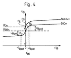
- FIG. 4 schematically represents, in a greatly enlarged manner, any of the curves of FIG. 3 in the vicinity of the vertical axis U B , that is to say in the vicinity of the no-load voltage U B0 for a SOC n charge state.
- a bias voltage U Bpol For a positive or negative current I B to be established at the terminals of the battery, a bias voltage U Bpol must be added or subtracted from the no- load voltage U B0 respectively . Consequently, the curve has a very steep slope between a point P 3 , corresponding to a voltage U B0 -U Bpol and a current -I Bpol , and a point P 4 corresponding to a voltage U B0 + U Bpol and a current + I Bpol . It will be noted that the values ⁇ I Bpol are close to zero, the scale of FIG. 4 being greatly enlarged compared to that of FIG. 3.
- this characteristic is especially useful for stabilizing the distribution of electric powers when it is desired to cancel the battery current I B by an appropriate choice of the reference voltage U 0c .
- the state of charge being SOC n
- U 0c U B0n .
- the chosen setpoint voltage U 0c is for example slightly greater than U B0n .
- This then results in the operating point P 5 , corresponding to a current I B5 which enters the battery. As this current is less than I Bpol , it is very low and practically does not affect the desired distribution of power flows.
- the method according to the invention allows a particularly precise and stable adjustment when it is desired to maintain low or zero values of the current of the battery 6.
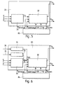
- FIG. 5 shows the arrangement of the control unit 20 for applying the method described above, by managing the operation of the battery 6.
- the unit 31 of FIG. 2 is replaced by a unit for distributing the fluxes of power 32, which receives the signal P C and exchanges with the battery management unit 26 the set of signals 29 shown in FIG. 1.
- the signals delivered by the unit 26 include a signal SOC constantly indicating the state of current charge of the battery 6, two signals P charge and P discharge constantly indicating the limits of the window for operating the battery at this state of charge, namely the maximum admissible power respectively for charging and discharging the battery, and a signal U B which responds to a requested power signal P Bdem transmitted by the unit 32.
- This power is positive to charge the battery, negative to discharge it or zero if we want to maintain the current state of charge.
- the signal U B indicates the voltage corresponding to the requested power P Bdem , as explained above.
- the unit 32 calculates the signal P Bdem as a function of the signal P c , indicating the desired traction or braking power as in the case of FIG. 2, and of a choice of an optimal distribution of the power between the members connected to supply circuit 2. This calculation takes SOC, P Bcharge and P Bdischarge into account .
- the unit 32 then fixes the setpoint voltage U 0c at the value U B supplied by the unit 26, and it delivers to the generator group 1 its power setpoint P Gc .
- the battery 6 will absorb or supply the power indicated by P Bdem , while the propellant assembly will maintain its power at a value equal to P Gc -P Bdem .
- FIG. 6 shows an improved variant of the diagram of FIG. 5, where the unit of distribution of power 32 also receives Rend and Dyn signals optimizing the power distribution in real time, depending on the current operating state various parts of the vehicle.
- the control unit 20 then includes a performance management unit for the vehicle 33 and a dynamic management unit for the vehicle 34.
- Unit 33 receives signals 35 indicating current organ status or performance parameters affected, and it calculates the Rend signal based on these signals and functions or algorithms to define a preferable distribution of power which corresponds to optimal overall performance.
- Unit 34 receives signals 36 showing current dynamic parameters of the vehicle and it calculates the Dyn signal accordingly, for allow unit 32 to anticipate the future state of the system when choosing the optimal distribution of the power.
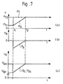
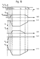
- FIG. 7 illustrate the evolution of certain parameters as a function of time t in the system having the configuration according to FIG. 5, when the action of the driver on the accelerator pedal 21 commands an increase in traction power which can be fully covered by generator group 1.
- Diagram (a) shows that the power PT desired by the driver and consumed by the propellant assembly rises from P T1 to P T2 at time t 1 when the driver presses the accelerator.
- the electric power PG supplied by the generator group 1 in accordance with the setpoint signal P Gc then gradually increases to a value equal to P T2 at time t 2 , then it remains at this value.
- the unit 32 temporarily lowers the voltage U 0 of the supply circuit by imposing a corresponding set value U 0c , as shown in diagram (c).
- the diagrams (a), (b) and (c) of FIG. 8 correspond to those of FIG. 7, but for a case where the power PG of the generator group cannot exceed a value P G3 less than P T2 .
- FIG. 9 illustrates a case of electrical braking in accordance with the present invention in a drive system which comprises, in accordance with FIG. 1, a battery 6 and a safety device 7 and which is controlled in accordance with the diagram in FIG. 5.
- Diagrams (a), (b), (e) and (f) represent the evolution of parameters already described above.
- Diagram (c) represents the setpoint signal S c controlling the safety device 7, and diagram (d) represents the power P S absorbed by this device.
- the vehicle Before an instant t 0 , the vehicle is in traction mode, controlled by a signal T (FIGS. 1 and 5), but the driver releases the accelerator and the signal T disappears at instant t 0 .
- a brake signal F produced by an additional release of the accelerator or by actuation of the brake pedal.
- the control unit 20 then raises the setpoint voltage U 0c , from its value U 01 which corresponded to a zero battery current, until it reaches a value U 02 corresponding to a maximum power of charge P B charge (or less power) of the battery at time t 2 . Beyond this, the additional braking power will be absorbed by the safety device 7 controlled by the signal S c to reach a determined power P S.
- the balance of electrical powers continues to be ensured by the battery 6 operating in the vicinity of its maximum charging power.
- one of the signals X represented in FIG. 1 may indicate to unit 20 the nominal power engaged of the consumer body 8, without the need to measure the precise power absorbed by this organ.
- Figure 10 is a representation similar to that of Figure 9, but illustrates another embodiment of the method according to the invention in electric braking mode by means of the battery 6 and the safety device 7.
- the balancing of the electric powers by adjusting the voltage U 0 is not carried out on the propulsion unit 3, but on the safety member 7.
- a second is then provided electronic adjustment device 38 which controls the power of the safety member 7 in braking mode as does the adjustment unit 24 on the propulsion unit 3 in traction mode.
- the unit 24 In braking mode, the unit 24 no longer receives the voltage setpoint U 0c but a braking torque setpoint F c . It then "forgets" its voltage setting and it controls the negative power PT of the propulsion unit directly as a function of F c .
- the control unit 20 then delivers the voltage setpoint U 0c to the adjustment unit 38, which also receives the value U0 and consequently controls an increase or decrease in the power of the safety device 7 by a signal S F.
- Figure 10 shows the time evolution of the system parameters under the same circumstances as for Figure 9.
- Diagrams (a), (b), (d), (e) and (f) are identical to those in Figure 9.
- the diagram (c) represents the change in the braking torque setpoint F c , producing a change comparable to the braking power P T.
- the parameters represented vary as in Figure 9. From this moment, as the setpoint U 0c can no longer increase so as not to overcharge the battery 6, the increase in the power of electrical braking P T tends to raise the voltage U 0 of the supply circuit, so that the adjustment circuit 38 reacts and increases the power P S of the safety device 7 in order to automatically stabilize the voltage at the value U 0c .
- the braking setpoint F having disappeared, the system returns to the setting in traction mode, U 0c resuming its initial value.
- FIG. 11 illustrates an example of a drive system of a parallel hybrid vehicle according to the invention, where the effect of the generator group 1 is replaced by that of a heat engine 11 mechanically driving the drive wheels by means of its output shaft 40, a gearbox 41 and a transmission shaft 42, in parallel with the electric propeller assembly 3.
- the power of the engine 11 is controlled by the reference signal P Gc coming from the control unit 20.
- the power of this assembly can be adjusted by adjusting the supply voltage U 0 can be carried out exactly as described above.
- a mixed propulsion system for example, if we added to the system of FIG. 1 a mechanical drive link between the motor shaft 11 and the shaft 5 driving the drive wheel 4.
- the method according to the invention can also be used in a vehicle whose drive system is fully electric and powered by the battery 6 in traction mode, as shown in Figure 12. Compared to the system shown in Figure 1, this amounts to deleting the generator group 1 and the corresponding signal P Gc .
- This group could also be replaced by another adjustable electrical energy source such as a fuel cell, the power of which would be controlled by the signal P Gc .
Description
- la figure 1 est un schéma général d'un système d'entraínement d'un véhicule à propulsion hybride série dans lequel est appliqué le procédé selon l'invention;
- la figure 2 est un schéma fonctionnel de l'unité de commande du système de la figure 1, dans le cas où ce système est dépourvu de batterie et d'organe de sécurité;
- la figure 3 est un diagramme schématique des caractéristiques courant/tension aux bornes d'une batterie;
- la figure 4 représente à une échelle agrandie un détail des courbes de la figure 3;
- la figure 5 est un schéma fonctionnel de l'unité de commande du système de la figure 1, dans le cas où le système comporte une batterie;
- la figure 6 représente une variante du schéma de la figure 5;
- la figure 7 représente l'évolution de certaines variables dans le système en fonction du temps, pour une augmentation de demande de puissance qui peut être couverte par le groupe générateur;
- la figure 8 représente les mêmes variables que la figure 7, mais pour une augmentation de demande de puissance qui ne peut pas être couverte entièrement par le groupe générateur;
- la figure 9 représente l'évolution de certaines variables dans le système en fonction du temps pour le cas d'un freinage électrique alimentant la batterie et l'organe de sécurité;
- la figure 10 est analogue à la figure 9, mais illustre une autre forme d'exécution du procédé;
- la figure 11 est analogue à la figure 1, pour le cas d'un véhicule à propulsion hybride parallèle, et
- la figure 12 est analogue à la figure 1, pour le cas d'un véhicule à propulsion purement électrique.
Claims (11)
- Procédé pour régler la répartition de la puissance électrique dans un circuit d'alimentation à tension continue dans un véhicule automobile comportant plusieurs organes électriques (1, 3, 6, 7, 8) susceptibles de consommer et/ou produire de la puissance sur le circuit d'alimentation, l'un desdits organes électriques étant un ensemble propulseur électrique (3) susceptible d'entraíner au moins une roue motrice (4) du véhicule, le procédé étant caractérisé en ce que, dans un mode de traction, on définit l'ensemble propulseur (3) comme organe d'équilibrage de puissance, lequel échange une puissance réglée avec le circuit d'alimentation (2), on détermine une tension de consigne (U0c) du circuit d'alimentation, on surveille continuellement une tension effective (U0) du circuit d'alimentation et l'on règle la puissance de l'organe d'équilibrage de façon à maintenir ladite tension effective au niveau de ladite tension de consigne.
- Procédé selon la revendication 1, dans lequel l'un desdits organes électriques est un groupe générateur (1) susceptible d'échanger sur commande une première puissance avec le circuit d'alimentation (2), caractérisé en ce qu'on commande ladite première puissance sur la base d'une demande de puissance ou de couple (T, F) donnée par un conducteur du véhicule.
- Procédé selon la revendication 1 ou 2, dans lequel lesdits organes électriques comprennent une batterie électrique (6), caractérisé en ce qu'on surveille un état de charge de la batterie (6) et l'on détermine la tension de consigne (U0c) en fonction dudit état de charge.
- Procédé selon la revendication 3, caractérisé en ce que pour déterminer la tension de consigne en fonction de l'état de charge, on utilise une relation caractéristique prédéterminée entre le courant (IB) et la tension (UB) aux bornes de la batterie pour chaque état de charge.
- Procédé selon la revendication 4, caractérisé en ce que pour déterminer une valeur nulle de la puissance échangée entre la batterie (6) et le circuit d'alimentation (2), on détermine la tension de consigne (U0c) comme égale à la tension à vide (UB0) de la batterie pour son état de charge actuel.
- Procédé selon la revendication 4, caractérisé en ce que pour porter la batterie (6) à un état de charge voulu qui est inférieur ou supérieur à l'état de charge actuel, on détermine la tension de consigne (U0c) comme égale à la tension à vide (UB07) de la batterie à l'état de charge voulu.
- Procédé selon l'une des revendications 1 à 3, dans lequel lesdits organes électriques comprennent un organe de sécurité (7) destiné à consommer de la puissance excédentaire lorsque l'ensemble propulseur (3) est utilisé pour un freinage électrique, caractérisé en ce que, dans un mode de freinage électrique, on fait fonctionner l'organe de sécurité (7) à une puissance déterminée et l'on utilise l'ensemble propulseur (3) comme organe d'équilibrage fournissant une puissance au circuit d'alimentation.
- Système d'entraínement pour véhicule automobile, notamment pour la mise en oeuvre du procédé selon la revendication 1, ledit système comportant plusieurs organes électriques (1, 3, 6, 7, 8) susceptibles de consommer et/ou produire de la puissance sur le circuit d'alimentation, l'un desdits organes étant un ensemble propulseur électrique réglable (3) susceptible d'entraíner au moins une roue motrice (4) du véhicule, et des moyens de commande agencés pour commander la puissance de l'ensemble propulseur (3), lequel échange une deuxième puissance avec le circuit d'alimentation (2), les moyens de commande étant agencés pour surveiller continuellement la tension effective (U0) du circuit d'alimentation, caractérisé en ce que les moyens de commande (20 - 38) comportent une unité électronique de réglage (24) associée à l'ensemble propulseur (3) et agencée pour régler la puissance de celui-ci dans un mode de traction sur la base d'une tension de consigne (U0c) définie par les moyens de commande, de façon à maintenir ladite tension effective au niveau de ladite tension de consigne.
- Système d'entraínement selon la revendication 8, caractérisé en ce que l'un desdits organes électriques est un groupe générateur (1) susceptible de fournir sur commande une première puissance à un circuit d'alimentation (2) à tension continue, et en ce que les moyens de commande (20 - 38) sont agencés pour commander ladite première puissance sur la base d'une demande de puissance donnée par un conducteur du véhicule.
- Système d'entraínement selon la revendication 8 ou 9, caractérisé en ce que lesdits organes électriques comprennent une batterie électrique (6) raccordée au circuit d'alimentation (2).
- Système d'entraínement selon l'une des revendications 8 à 10, caractérisé en ce que lesdits organes électriques comprennent un organe de sécurité (7) destiné à consommer de la puissance excédentaire lorsque l'ensemble propulseur (3) est utilisé dans un mode de freinage électrique.
Applications Claiming Priority (2)
| Application Number | Priority Date | Filing Date | Title |
|---|---|---|---|
| FR9600093A FR2743342B1 (fr) | 1996-01-05 | 1996-01-05 | Procede et dispositif pour regler la repartition de la puissance electrique dans un vehicule automobile, notamment la propulsion hybride |
| FR9600093 | 1996-01-05 |
Publications (2)
| Publication Number | Publication Date |
|---|---|
| EP0782941A1 EP0782941A1 (fr) | 1997-07-09 |
| EP0782941B1 true EP0782941B1 (fr) | 2003-03-19 |
Family
ID=9487917
Family Applications (1)
| Application Number | Title | Priority Date | Filing Date |
|---|---|---|---|
| EP96120329A Expired - Lifetime EP0782941B1 (fr) | 1996-01-05 | 1996-12-18 | Procédé et dispositif pour régler la répartition de la puissance électrique dans un véhicule automobile, notamment à propulsion hybride |
Country Status (11)
| Country | Link |
|---|---|
| US (1) | US5847520A (fr) |
| EP (1) | EP0782941B1 (fr) |
| JP (1) | JP3969548B2 (fr) |
| KR (1) | KR970058982A (fr) |
| CN (1) | CN1051044C (fr) |
| AT (1) | ATE234747T1 (fr) |
| AU (1) | AU7650696A (fr) |
| BR (1) | BR9700010A (fr) |
| CA (1) | CA2194319A1 (fr) |
| DE (1) | DE69626771T2 (fr) |
| FR (1) | FR2743342B1 (fr) |
Families Citing this family (87)
| Publication number | Priority date | Publication date | Assignee | Title |
|---|---|---|---|---|
| JP3608017B2 (ja) * | 1996-07-22 | 2005-01-05 | トヨタ自動車株式会社 | 電源システム |
| JP4049833B2 (ja) * | 1996-07-26 | 2008-02-20 | トヨタ自動車株式会社 | 電源装置および電気自動車 |
| JP4372235B2 (ja) * | 1996-08-29 | 2009-11-25 | トヨタ自動車株式会社 | 燃料電池システムおよび電気自動車 |
| DE19731642C1 (de) * | 1997-07-23 | 1999-02-18 | Dbb Fuel Cell Engines Gmbh | Brennstoffzellenfahrzeug |
| US5941328A (en) * | 1997-11-21 | 1999-08-24 | Lockheed Martin Corporation | Electric vehicle with variable efficiency regenerative braking depending upon battery charge state |
| US5929595A (en) * | 1997-11-21 | 1999-07-27 | Lockheed Martin Corporation | Hybrid electric vehicle with traction motor drive allocated between battery and auxiliary source depending upon battery charge state |
| DE19826551C1 (de) * | 1998-06-15 | 1999-11-18 | Siemens Ag | Steuerungssystem für ein aus mindestens einem Energiespeicher und einer Energiequelle bestehendes Hybridsystem |
| US6885920B2 (en) * | 1999-07-30 | 2005-04-26 | Oshkosh Truck Corporation | Control system and method for electric vehicle |
| US6757597B2 (en) | 2001-01-31 | 2004-06-29 | Oshkosh Truck | A/C bus assembly for electronic traction vehicle |
| WO2001015929A1 (fr) * | 1999-08-27 | 2001-03-08 | Yamaha Hatsudoki Kabushiki Kaisha | Système d'entraînement hybride |
| US6196344B1 (en) | 1999-09-10 | 2001-03-06 | Ford Global Technologies, Inc. | Control system and method for a hybrid electric vehicle |
| CA2320003C (fr) * | 1999-09-22 | 2006-03-21 | Honda Giken Kogyo Kabushiki Kaisha | Appareil de commande destine aux vehicules hybrides |
| US6242873B1 (en) * | 2000-01-31 | 2001-06-05 | Azure Dynamics Inc. | Method and apparatus for adaptive hybrid vehicle control |
| JP3654128B2 (ja) * | 2000-04-06 | 2005-06-02 | 日産自動車株式会社 | 車両用制御装置 |
| FR2809998B1 (fr) * | 2000-06-07 | 2004-04-02 | Renault | Procede de commande d'un vehicule hybride a transmission electrique |
| JP3513085B2 (ja) * | 2000-06-27 | 2004-03-31 | 三菱電機株式会社 | 車両用発電機の電圧制御装置 |
| JP4070401B2 (ja) * | 2000-10-31 | 2008-04-02 | 日産ディーゼル工業株式会社 | 車両のハイブリッドシステム |
| US6452352B1 (en) | 2000-11-02 | 2002-09-17 | Ballard Power Systems Corporation | Method of current interaction in an electric motor drive system having a load-dependent current generating system |
| DE10064188A1 (de) * | 2000-12-22 | 2002-07-11 | Magnet Motor Gmbh | Verfahren zum Betreiben eines nichtschienengebundenen Land-Kraftfahrzeugs mit Verbrennungsmotor-Generator-Einheit und Antriebs-Elektromotor, und derartiges Kraftfahrzeug |
| US20040174125A1 (en) * | 2000-12-27 | 2004-09-09 | Transportation Techniques Llc | Method and apparatus for adaptive control of hybrid electric vehicle components |
| US7338335B1 (en) * | 2001-01-23 | 2008-03-04 | Frank Messano | Hybrid electric heavy-duty vehicle drive system |
| US7379797B2 (en) | 2001-01-31 | 2008-05-27 | Oshkosh Truck Corporation | System and method for braking in an electric vehicle |
| US7277782B2 (en) * | 2001-01-31 | 2007-10-02 | Oshkosh Truck Corporation | Control system and method for electric vehicle |
| JP3714405B2 (ja) | 2001-03-15 | 2005-11-09 | 日産自動車株式会社 | 車両の制御装置 |
| DE10137908A1 (de) * | 2001-08-02 | 2003-02-27 | Siemens Ag | Hybridantriebssystem und Verfahren zur Regelung des Hybridantriebssystems |
| US6959777B2 (en) * | 2001-10-05 | 2005-11-01 | Ford Global Technologies, Llc | High voltage energy regulated conversion circuit |
| US7302320B2 (en) | 2001-12-21 | 2007-11-27 | Oshkosh Truck Corporation | Failure mode operation for an electric vehicle |
| US7520354B2 (en) | 2002-05-02 | 2009-04-21 | Oshkosh Truck Corporation | Hybrid vehicle with combustion engine/electric motor drive |
| FR2848602B1 (fr) * | 2002-12-12 | 2008-01-04 | Irisbus France | Systeme de motorisation pour equipement auxiliaire de vehicule |
| US8025115B2 (en) | 2003-06-02 | 2011-09-27 | General Electric Company | Hybrid vehicle power control systems and methods |
| KR100588500B1 (ko) * | 2003-09-24 | 2006-06-13 | 현대자동차주식회사 | 모터를 이용한 사륜구동 장치 및 그 제어방법 |
| US7100362B2 (en) * | 2004-07-30 | 2006-09-05 | Ford Global Technologies, Llc | Vehicle and method for operating a vehicle to reduce exhaust emissions |
| US7439711B2 (en) | 2004-09-27 | 2008-10-21 | Oshkosh Corporation | Energy storage device including a status indicator |
| DE102004051530A1 (de) * | 2004-10-22 | 2006-05-04 | Audi Ag | Kraftfahrzeug mit einem Rekuperationsgenerator |
| US7444944B2 (en) * | 2005-06-15 | 2008-11-04 | General Electric Company | Multiple engine hybrid locomotive |
| EP1935101B1 (fr) * | 2005-09-23 | 2014-04-23 | AFS Trinity Power Corporation | Procede et appareil d'alimentation de dispositifs electoniques et de commande d'une propulsion hybride enfichable comprenant un dispositif de stockage rapide d'energie |
| JP2007137299A (ja) * | 2005-11-21 | 2007-06-07 | Toyota Motor Corp | 電源供給制御装置 |
| DE102006005477B4 (de) * | 2006-02-03 | 2007-10-11 | Veit Wilhelm | Vorrichtung zur Erzeugung von Strom, sowie Kraftfahrzeug mit Elektroantrieb und solcher Vorrichtung |
| US8947531B2 (en) | 2006-06-19 | 2015-02-03 | Oshkosh Corporation | Vehicle diagnostics based on information communicated between vehicles |
| US8139109B2 (en) | 2006-06-19 | 2012-03-20 | Oshkosh Corporation | Vision system for an autonomous vehicle |
| US7436081B2 (en) * | 2007-01-31 | 2008-10-14 | Caterpillar Inc. | System for controlling a hybrid energy system |
| CN108909463A (zh) * | 2007-05-10 | 2018-11-30 | 奥克兰联合服务有限公司 | 多电源电气车辆 |
| US8248984B2 (en) * | 2007-06-20 | 2012-08-21 | I Squared Llc | System and method for interfacing devices |
| JP4363478B2 (ja) | 2007-10-29 | 2009-11-11 | トヨタ自動車株式会社 | 燃料電池の出力制御装置 |
| JP4462366B2 (ja) * | 2008-04-01 | 2010-05-12 | トヨタ自動車株式会社 | 動力出力装置およびこれを備える車両並びに動力出力装置の制御方法 |
| US20100108417A1 (en) * | 2008-10-31 | 2010-05-06 | Curt Douglas Gilmore | Parallel power supplies for hev applications |
| DE102008061956A1 (de) * | 2008-12-12 | 2009-09-17 | Daimler Ag | Verfahren und Anordnung zur Regelung einer Generatorspannung in einem Kraftfahrzeug |
| DE202009015027U1 (de) * | 2009-11-04 | 2010-02-18 | Fischer Panda Gmbh | Vorrichtung zum Steuern eines Fahrzeugs |
| DE202009015026U1 (de) * | 2009-11-04 | 2010-03-04 | Fischer Panda Gmbh | Vorrichtung zum Antrieb eines Fahrzeugs, insbesondere eines Wasserfahrzeugs |
| US8337352B2 (en) | 2010-06-22 | 2012-12-25 | Oshkosh Corporation | Electromechanical variable transmission |
| US9145061B2 (en) * | 2011-12-14 | 2015-09-29 | Mitsubishi Electric Corporation | Hybrid-vehicle power generator control apparatus |
| DE102011088973A1 (de) * | 2011-12-19 | 2013-06-20 | Robert Bosch Gmbh | Verfahren und Vorrichtung zum Anpassen einer Spannungsgrenze in einem Bordnetz |
| DE102012222343A1 (de) | 2012-12-05 | 2014-06-05 | Robert Bosch Gmbh | Verfahren zum Bereitstellen einer Versorgungsspannung und elektrisches Antriebssystem |
| FR3002905B1 (fr) * | 2013-03-05 | 2015-03-27 | Peugeot Citroen Automobiles Sa | Procede de pilotage d'une machine electrique d'un vehicule automobile hybride |
| US9114804B1 (en) | 2013-03-14 | 2015-08-25 | Oshkosh Defense, Llc | Vehicle drive and method with electromechanical variable transmission |
| US9719477B2 (en) | 2013-12-09 | 2017-08-01 | Textron Inc. | Using a DC or AC generator as a starter with fault detection |
| US9272628B2 (en) | 2013-12-09 | 2016-03-01 | Textron Inc. | Using AC induction motor as a generator in a utility vehicle |
| DE102014202103B4 (de) * | 2014-02-05 | 2023-11-16 | Bayerische Motoren Werke Aktiengesellschaft | Verfahren und Steuervorrichtung zum Betrieb eines straßengekoppelten Hybridfahrzeuges |
| US20150283908A1 (en) * | 2014-04-02 | 2015-10-08 | Hamilton Sundstrand Corporation | Systems utilizing a controllable voltage ac generator system |
| US9193273B1 (en) * | 2014-06-15 | 2015-11-24 | Efficient Drivetrains, Inc. | Vehicle with AC-to-DC inverter system for vehicle-to-grid power integration |
| CN105281624B (zh) * | 2014-06-17 | 2021-04-06 | 松下知识产权经营株式会社 | 热动力发电装置和热动力发电系统 |
| JP6350012B2 (ja) * | 2014-06-23 | 2018-07-04 | 三菱自動車工業株式会社 | 車両の回生制御装置 |
| JP2016032977A (ja) * | 2014-07-31 | 2016-03-10 | 株式会社デンソー | 電動パワーステアリングシステムおよび車両制御システム |
| US9878632B2 (en) * | 2014-08-19 | 2018-01-30 | General Electric Company | Vehicle propulsion system having an energy storage system and optimized method of controlling operation thereof |
| EP3017995A1 (fr) * | 2014-11-05 | 2016-05-11 | ABB Technology Oy | Procédé de réglage d'un entraînement électronique régulé et appareil pour sa mise en oeuvre |
| US9650032B2 (en) | 2015-02-17 | 2017-05-16 | Oshkosh Corporation | Multi-mode electromechanical variable transmission |
| US10421350B2 (en) | 2015-10-20 | 2019-09-24 | Oshkosh Corporation | Inline electromechanical variable transmission system |
| US9651120B2 (en) | 2015-02-17 | 2017-05-16 | Oshkosh Corporation | Multi-mode electromechanical variable transmission |
| US10578195B2 (en) | 2015-02-17 | 2020-03-03 | Oshkosh Corporation | Inline electromechanical variable transmission system |
| US9656659B2 (en) | 2015-02-17 | 2017-05-23 | Oshkosh Corporation | Multi-mode electromechanical variable transmission |
| US10584775B2 (en) | 2015-02-17 | 2020-03-10 | Oshkosh Corporation | Inline electromechanical variable transmission system |
| US11701959B2 (en) | 2015-02-17 | 2023-07-18 | Oshkosh Corporation | Inline electromechanical variable transmission system |
| US10982736B2 (en) | 2015-02-17 | 2021-04-20 | Oshkosh Corporation | Multi-mode electromechanical variable transmission |
| DE102016208455A1 (de) * | 2016-05-17 | 2017-11-23 | Bayerische Motoren Werke Aktiengesellschaft | Verfahren und Steuereinheit zur Reduzierung der Zyklisierung eines Energiespeichers |
| CN106129507B (zh) * | 2016-09-05 | 2018-09-21 | 北京新能源汽车股份有限公司 | 一种电动汽车电池充电的控制方法、装置和电动汽车 |
| CN107499259B (zh) * | 2017-09-20 | 2024-04-16 | 中国重汽集团济南动力有限公司 | 一种多轴轮驱电动汽车用分布式控制电配电系统 |
| FR3084318B1 (fr) | 2018-07-25 | 2020-06-26 | Airbus Helicopters | Procede et dispositif de gestion de l'energie d'une installation motrice hybride d'un aeronef multirotor |
| US11396388B2 (en) | 2018-12-20 | 2022-07-26 | The Boeing Company | Optimized power balanced variable thrust transfer orbits to minimize an electric orbit raising duration |
| US11401053B2 (en) * | 2018-12-20 | 2022-08-02 | The Boeing Company | Autonomous control of electric power supplied to a thruster during electric orbit raising |
| US11753188B2 (en) | 2018-12-20 | 2023-09-12 | The Boeing Company | Optimized power balanced low thrust transfer orbits utilizing split thruster execution |
| US11817811B2 (en) | 2019-03-12 | 2023-11-14 | Allegro Microsystems, Llc | Motor controller with power feedback loop |
| DE102019209952A1 (de) * | 2019-07-05 | 2021-01-07 | Zf Friedrichshafen Ag | Verfahren zum Betreiben eines Fahrmischers |
| DE102019121277A1 (de) | 2019-08-07 | 2021-02-11 | Bayerische Motoren Werke Aktiengesellschaft | Mehrspannungs-Speichersystem für ein zumindest teilweise elektrisch angetriebenes Fahrzeug |
| US11803164B2 (en) * | 2020-12-01 | 2023-10-31 | DemandQ, Inc. | Controlling power distribution serving an aggregate of electrical loads behind a meter |
| FR3123324B1 (fr) * | 2021-05-31 | 2023-04-21 | Airbus Helicopters | Procédé d’aide au pilotage d’un giravion en hautes altitudes grâce à l’apport d’une puissance mécanique provenant d’une installation motrice électrique |
| CN113561792B (zh) * | 2021-06-30 | 2023-04-25 | 东风汽车集团股份有限公司 | 混合动力汽车功率平衡控制方法、计算机设备及存储介质 |
| CN113968136B (zh) * | 2021-10-29 | 2023-11-10 | 华人运通(江苏)技术有限公司 | 一种电动汽车的低压能量控制方法、系统、设备及介质 |
Family Cites Families (10)
| Publication number | Priority date | Publication date | Assignee | Title |
|---|---|---|---|---|
| JP2932607B2 (ja) * | 1990-05-23 | 1999-08-09 | 日産自動車株式会社 | 電気自動車 |
| GB9012365D0 (en) * | 1990-06-02 | 1990-07-25 | Jaguar Cars | Motor vehicles |
| DE4133059A1 (de) * | 1991-10-04 | 1993-04-08 | Mannesmann Ag | Antriebsanordnung fuer ein kraftfahrzeug |
| JP3044880B2 (ja) * | 1991-11-22 | 2000-05-22 | トヨタ自動車株式会社 | シリーズハイブリッド車の駆動制御装置 |
| DE4344053B4 (de) * | 1993-01-08 | 2005-06-16 | Volkswagen Ag | Verfahren zum Betrieb eines Hybridfahrzeugs und Vorrichtung zum Durchführen des Verfahrens |
| JP3094745B2 (ja) * | 1993-09-24 | 2000-10-03 | トヨタ自動車株式会社 | ハイブリッド車の発電制御装置 |
| US5359308A (en) * | 1993-10-27 | 1994-10-25 | Ael Defense Corp. | Vehicle energy management system using superconducting magnetic energy storage |
| US5345761A (en) * | 1993-12-02 | 1994-09-13 | Ford Motor Company | Energy management system for hybrid vehicle |
| JP3336777B2 (ja) * | 1994-10-25 | 2002-10-21 | 株式会社エクォス・リサーチ | ハイブリッド車両及びハイブリッド車両の制御方法 |
| US5765656A (en) * | 1996-01-18 | 1998-06-16 | Weaver; Winstead B. | Hybrid electric motor vehicle drive |
-
1996
- 1996-01-05 FR FR9600093A patent/FR2743342B1/fr not_active Expired - Lifetime
- 1996-12-18 DE DE69626771T patent/DE69626771T2/de not_active Expired - Lifetime
- 1996-12-18 EP EP96120329A patent/EP0782941B1/fr not_active Expired - Lifetime
- 1996-12-18 AT AT96120329T patent/ATE234747T1/de active
- 1996-12-24 AU AU76506/96A patent/AU7650696A/en not_active Abandoned
-
1997
- 1997-01-03 CA CA002194319A patent/CA2194319A1/fr not_active Abandoned
- 1997-01-03 US US08/774,729 patent/US5847520A/en not_active Expired - Lifetime
- 1997-01-03 KR KR1019970000006A patent/KR970058982A/ko not_active Application Discontinuation
- 1997-01-03 BR BR9700010A patent/BR9700010A/pt active Search and Examination
- 1997-01-04 CN CN97102923A patent/CN1051044C/zh not_active Expired - Fee Related
- 1997-01-06 JP JP1008797A patent/JP3969548B2/ja not_active Expired - Fee Related
Also Published As
| Publication number | Publication date |
|---|---|
| KR970058982A (ko) | 1997-08-12 |
| FR2743342B1 (fr) | 1998-02-13 |
| DE69626771T2 (de) | 2004-03-25 |
| DE69626771D1 (de) | 2003-04-24 |
| CN1174790A (zh) | 1998-03-04 |
| JPH09331601A (ja) | 1997-12-22 |
| AU7650696A (en) | 1997-07-10 |
| FR2743342A1 (fr) | 1997-07-11 |
| US5847520A (en) | 1998-12-08 |
| CA2194319A1 (fr) | 1997-07-06 |
| EP0782941A1 (fr) | 1997-07-09 |
| CN1051044C (zh) | 2000-04-05 |
| JP3969548B2 (ja) | 2007-09-05 |
| ATE234747T1 (de) | 2003-04-15 |
| BR9700010A (pt) | 1998-11-10 |
Similar Documents
| Publication | Publication Date | Title |
|---|---|---|
| EP0782941B1 (fr) | Procédé et dispositif pour régler la répartition de la puissance électrique dans un véhicule automobile, notamment à propulsion hybride | |
| FR2851516A1 (fr) | Procede de commande de systeme electrique de vehicule | |
| FR2898742A1 (fr) | Dispositif de commande permettant une commande economique et fiable d'un generateur electrique. | |
| EP2885147B1 (fr) | Procede de limitation de couple d'une machine electrique de vehicule hybride comportant un systeme de controle de vitesse | |
| EP1428712B1 (fr) | Chaîne de traction et procedé de réglage pour véhicule hybride série | |
| CA2194320A1 (fr) | Systeme d'entrainement pour vehicule automobile a propulsion hybride et son procede de commande | |
| EP2504195A2 (fr) | Onduleur de pilotage d'un moteur electrique comportant un regulateur integre | |
| EP1224092B1 (fr) | Procede de commande d'un vehicule hybride | |
| EP2073371B1 (fr) | Procédé de pilotage d'un alternateur de véhicule automobile | |
| WO2012159884A2 (fr) | Installation comprenant une source d'energie electrique comportant au moins deux elements de technologies differentes et un onduleur de pilotage d'un moteur electrique a courant alternatif | |
| WO2021043682A1 (fr) | Procédé de gestion de la répartition de couple dans un véhicule hybride | |
| EP1452383B1 (fr) | Système de régulation mécanique du dispositif de transmission de mouvement pour un véhicule automobile | |
| FR3092210A1 (fr) | Procede de gestion de l’alimentation de deux reseaux electriques d’un vehicule automobile connectes entre eux | |
| FR3092212A1 (fr) | Procede et systeme de gestion de l’alimentation d’un reseau de bord d’un vehicule automobile | |
| FR3026992A1 (fr) | Procede de pilotage d'un dispositif de charge de batterie, au regime moteur de ralenti | |
| EP2789096A2 (fr) | Procede et systeme de regulation d'un alternateur de vehicule automobile, et alternateur de vehicule automobile comprenant un tel systeme | |
| FR2801253A1 (fr) | Procede de recuperation d'energie sur un vehicule en deceleration | |
| FR2783768A1 (fr) | Procede de commande d'un vehicule hybride a transmission electrique serie | |
| WO2007122344A2 (fr) | Procede d'optimisation de la generation electrique dans un vehicule | |
| FR2911018A1 (fr) | Procede de controle du couple d'un alternateur d'un vehicule automobile et systeme de mise en oeuvre de ce procede. | |
| EP1454786A2 (fr) | Commande d'une machine électrique d'un véhicule hybride série | |
| EP4331073A1 (fr) | Gestion de la tension de recharge cible d'une batterie électrique rechargeable pour véhicule automobile | |
| FR2809998A1 (fr) | Procede de commande d'un vehicule hybride a transmission electrique | |
| WO2020157394A1 (fr) | Procede de pilotage d'un generateur couple a une roue-libre d'un vehicule automobile | |
| WO2023094264A1 (fr) | Procede de refroidissement optimise d'une batterie de vehicule electrique ou hybride |
Legal Events
| Date | Code | Title | Description |
|---|---|---|---|
| PUAI | Public reference made under article 153(3) epc to a published international application that has entered the european phase |
Free format text: ORIGINAL CODE: 0009012 |
|
| AK | Designated contracting states |
Kind code of ref document: A1 Designated state(s): AT BE CH DE ES GB IT LI NL SE |
|
| 17P | Request for examination filed |
Effective date: 19980109 |
|
| RAP1 | Party data changed (applicant data changed or rights of an application transferred) |
Owner name: THE SWATCH GROUP MANAGEMENT SERVICES AG |
|
| 17Q | First examination report despatched |
Effective date: 19990721 |
|
| GRAG | Despatch of communication of intention to grant |
Free format text: ORIGINAL CODE: EPIDOS AGRA |
|
| GRAG | Despatch of communication of intention to grant |
Free format text: ORIGINAL CODE: EPIDOS AGRA |
|
| GRAH | Despatch of communication of intention to grant a patent |
Free format text: ORIGINAL CODE: EPIDOS IGRA |
|
| GRAH | Despatch of communication of intention to grant a patent |
Free format text: ORIGINAL CODE: EPIDOS IGRA |
|
| GRAA | (expected) grant |
Free format text: ORIGINAL CODE: 0009210 |
|
| AK | Designated contracting states |
Designated state(s): AT BE CH DE ES GB IT LI NL SE |
|
| PG25 | Lapsed in a contracting state [announced via postgrant information from national office to epo] |
Ref country code: NL Free format text: LAPSE BECAUSE OF FAILURE TO SUBMIT A TRANSLATION OF THE DESCRIPTION OR TO PAY THE FEE WITHIN THE PRESCRIBED TIME-LIMIT Effective date: 20030319 Ref country code: GB Free format text: LAPSE BECAUSE OF FAILURE TO SUBMIT A TRANSLATION OF THE DESCRIPTION OR TO PAY THE FEE WITHIN THE PRESCRIBED TIME-LIMIT Effective date: 20030319 |
|
| REG | Reference to a national code |
Ref country code: GB Ref legal event code: FG4D Free format text: NOT ENGLISH |
|
| REG | Reference to a national code |
Ref country code: CH Ref legal event code: EP |
|
| REF | Corresponds to: |
Ref document number: 69626771 Country of ref document: DE Date of ref document: 20030424 Kind code of ref document: P |
|
| PG25 | Lapsed in a contracting state [announced via postgrant information from national office to epo] |
Ref country code: SE Free format text: LAPSE BECAUSE OF FAILURE TO SUBMIT A TRANSLATION OF THE DESCRIPTION OR TO PAY THE FEE WITHIN THE PRESCRIBED TIME-LIMIT Effective date: 20030619 |
|
| REG | Reference to a national code |
Ref country code: CH Ref legal event code: NV Representative=s name: HEPP, WENGER & RYFFEL AG |
|
| NLV1 | Nl: lapsed or annulled due to failure to fulfill the requirements of art. 29p and 29m of the patents act | ||
| GBV | Gb: ep patent (uk) treated as always having been void in accordance with gb section 77(7)/1977 [no translation filed] |
Effective date: 20030319 |
|
| PG25 | Lapsed in a contracting state [announced via postgrant information from national office to epo] |
Ref country code: ES Free format text: LAPSE BECAUSE OF FAILURE TO SUBMIT A TRANSLATION OF THE DESCRIPTION OR TO PAY THE FEE WITHIN THE PRESCRIBED TIME-LIMIT Effective date: 20030930 |
|
| PG25 | Lapsed in a contracting state [announced via postgrant information from national office to epo] |
Ref country code: BE Free format text: LAPSE BECAUSE OF NON-PAYMENT OF DUE FEES Effective date: 20031231 |
|
| PLBE | No opposition filed within time limit |
Free format text: ORIGINAL CODE: 0009261 |
|
| STAA | Information on the status of an ep patent application or granted ep patent |
Free format text: STATUS: NO OPPOSITION FILED WITHIN TIME LIMIT |
|
| 26N | No opposition filed |
Effective date: 20031222 |
|
| BERE | Be: lapsed |
Owner name: THE *SWATCH GROUP MANAGEMENT SERVICES A.G. Effective date: 20031231 |
|
| PGFP | Annual fee paid to national office [announced via postgrant information from national office to epo] |
Ref country code: DE Payment date: 20141121 Year of fee payment: 19 Ref country code: CH Payment date: 20141126 Year of fee payment: 19 |
|
| PGFP | Annual fee paid to national office [announced via postgrant information from national office to epo] |
Ref country code: AT Payment date: 20141124 Year of fee payment: 19 |
|
| PGFP | Annual fee paid to national office [announced via postgrant information from national office to epo] |
Ref country code: IT Payment date: 20141128 Year of fee payment: 19 |
|
| REG | Reference to a national code |
Ref country code: DE Ref legal event code: R119 Ref document number: 69626771 Country of ref document: DE |
|
| REG | Reference to a national code |
Ref country code: CH Ref legal event code: PL |
|
| REG | Reference to a national code |
Ref country code: AT Ref legal event code: MM01 Ref document number: 234747 Country of ref document: AT Kind code of ref document: T Effective date: 20151218 |
|
| PG25 | Lapsed in a contracting state [announced via postgrant information from national office to epo] |
Ref country code: LI Free format text: LAPSE BECAUSE OF NON-PAYMENT OF DUE FEES Effective date: 20151231 Ref country code: CH Free format text: LAPSE BECAUSE OF NON-PAYMENT OF DUE FEES Effective date: 20151231 Ref country code: DE Free format text: LAPSE BECAUSE OF NON-PAYMENT OF DUE FEES Effective date: 20160701 |
|
| PG25 | Lapsed in a contracting state [announced via postgrant information from national office to epo] |
Ref country code: AT Free format text: LAPSE BECAUSE OF NON-PAYMENT OF DUE FEES Effective date: 20151218 |
|
| PG25 | Lapsed in a contracting state [announced via postgrant information from national office to epo] |
Ref country code: IT Free format text: LAPSE BECAUSE OF NON-PAYMENT OF DUE FEES Effective date: 20151218 |