US11401053B2 - Autonomous control of electric power supplied to a thruster during electric orbit raising - Google Patents
Autonomous control of electric power supplied to a thruster during electric orbit raising Download PDFInfo
- Publication number
- US11401053B2 US11401053B2 US16/227,719 US201816227719A US11401053B2 US 11401053 B2 US11401053 B2 US 11401053B2 US 201816227719 A US201816227719 A US 201816227719A US 11401053 B2 US11401053 B2 US 11401053B2
- Authority
- US
- United States
- Prior art keywords
- thruster
- battery
- charge
- electric
- orbit
- Prior art date
- Legal status (The legal status is an assumption and is not a legal conclusion. Google has not performed a legal analysis and makes no representation as to the accuracy of the status listed.)
- Active, expires
Links
- 238000000034 method Methods 0.000 claims abstract description 34
- 239000003380 propellant Substances 0.000 claims abstract description 24
- 238000012545 processing Methods 0.000 claims description 58
- 230000004044 response Effects 0.000 claims description 20
- 238000010304 firing Methods 0.000 claims description 9
- 238000003491 array Methods 0.000 description 7
- 238000010586 diagram Methods 0.000 description 6
- 230000007246 mechanism Effects 0.000 description 3
- 238000000926 separation method Methods 0.000 description 3
- 229910052724 xenon Inorganic materials 0.000 description 3
- FHNFHKCVQCLJFQ-UHFFFAOYSA-N xenon atom Chemical compound [Xe] FHNFHKCVQCLJFQ-UHFFFAOYSA-N 0.000 description 3
- 230000001419 dependent effect Effects 0.000 description 2
- 238000002347 injection Methods 0.000 description 2
- 239000007924 injection Substances 0.000 description 2
- 239000000463 material Substances 0.000 description 2
- 230000007935 neutral effect Effects 0.000 description 2
- 230000001960 triggered effect Effects 0.000 description 2
- 102100033044 Glutathione peroxidase 2 Human genes 0.000 description 1
- 230000005355 Hall effect Effects 0.000 description 1
- 101000871129 Homo sapiens Glutathione peroxidase 2 Proteins 0.000 description 1
- 101000807306 Homo sapiens Ubiquitin-like modifier-activating enzyme 1 Proteins 0.000 description 1
- 102100037160 Ubiquitin-like modifier-activating enzyme 1 Human genes 0.000 description 1
- 230000006978 adaptation Effects 0.000 description 1
- 238000004590 computer program Methods 0.000 description 1
- 238000007599 discharging Methods 0.000 description 1
- 230000005484 gravity Effects 0.000 description 1
- 238000012986 modification Methods 0.000 description 1
- 230000004048 modification Effects 0.000 description 1
- 238000012544 monitoring process Methods 0.000 description 1
- 230000008569 process Effects 0.000 description 1
- 238000012546 transfer Methods 0.000 description 1
- 230000007704 transition Effects 0.000 description 1
Images


Classifications
-
- B64G1/007—
-
- B—PERFORMING OPERATIONS; TRANSPORTING
- B64—AIRCRAFT; AVIATION; COSMONAUTICS
- B64G—COSMONAUTICS; VEHICLES OR EQUIPMENT THEREFOR
- B64G1/00—Cosmonautic vehicles
- B64G1/22—Parts of, or equipment specially adapted for fitting in or to, cosmonautic vehicles
- B64G1/24—Guiding or controlling apparatus, e.g. for attitude control
- B64G1/242—Orbits and trajectories
- B64G1/2427—Transfer orbits
-
- B—PERFORMING OPERATIONS; TRANSPORTING
- B60—VEHICLES IN GENERAL
- B60L—PROPULSION OF ELECTRICALLY-PROPELLED VEHICLES; SUPPLYING ELECTRIC POWER FOR AUXILIARY EQUIPMENT OF ELECTRICALLY-PROPELLED VEHICLES; ELECTRODYNAMIC BRAKE SYSTEMS FOR VEHICLES IN GENERAL; MAGNETIC SUSPENSION OR LEVITATION FOR VEHICLES; MONITORING OPERATING VARIABLES OF ELECTRICALLY-PROPELLED VEHICLES; ELECTRIC SAFETY DEVICES FOR ELECTRICALLY-PROPELLED VEHICLES
- B60L58/00—Methods or circuit arrangements for monitoring or controlling batteries or fuel cells, specially adapted for electric vehicles
- B60L58/10—Methods or circuit arrangements for monitoring or controlling batteries or fuel cells, specially adapted for electric vehicles for monitoring or controlling batteries
- B60L58/12—Methods or circuit arrangements for monitoring or controlling batteries or fuel cells, specially adapted for electric vehicles for monitoring or controlling batteries responding to state of charge [SoC]
- B60L58/14—Preventing excessive discharging
-
- B—PERFORMING OPERATIONS; TRANSPORTING
- B64—AIRCRAFT; AVIATION; COSMONAUTICS
- B64G—COSMONAUTICS; VEHICLES OR EQUIPMENT THEREFOR
- B64G1/00—Cosmonautic vehicles
- B64G1/22—Parts of, or equipment specially adapted for fitting in or to, cosmonautic vehicles
- B64G1/24—Guiding or controlling apparatus, e.g. for attitude control
- B64G1/242—Orbits and trajectories
-
- B—PERFORMING OPERATIONS; TRANSPORTING
- B64—AIRCRAFT; AVIATION; COSMONAUTICS
- B64G—COSMONAUTICS; VEHICLES OR EQUIPMENT THEREFOR
- B64G1/00—Cosmonautic vehicles
- B64G1/22—Parts of, or equipment specially adapted for fitting in or to, cosmonautic vehicles
- B64G1/24—Guiding or controlling apparatus, e.g. for attitude control
- B64G1/26—Guiding or controlling apparatus, e.g. for attitude control using jets
-
- B—PERFORMING OPERATIONS; TRANSPORTING
- B64—AIRCRAFT; AVIATION; COSMONAUTICS
- B64G—COSMONAUTICS; VEHICLES OR EQUIPMENT THEREFOR
- B64G1/00—Cosmonautic vehicles
- B64G1/22—Parts of, or equipment specially adapted for fitting in or to, cosmonautic vehicles
- B64G1/40—Arrangements or adaptations of propulsion systems
- B64G1/405—Ion or plasma engines
-
- B—PERFORMING OPERATIONS; TRANSPORTING
- B64—AIRCRAFT; AVIATION; COSMONAUTICS
- B64G—COSMONAUTICS; VEHICLES OR EQUIPMENT THEREFOR
- B64G1/00—Cosmonautic vehicles
- B64G1/22—Parts of, or equipment specially adapted for fitting in or to, cosmonautic vehicles
- B64G1/42—Arrangements or adaptations of power supply systems
- B64G1/425—Power storage
-
- G—PHYSICS
- G05—CONTROLLING; REGULATING
- G05D—SYSTEMS FOR CONTROLLING OR REGULATING NON-ELECTRIC VARIABLES
- G05D1/00—Control of position, course or altitude of land, water, air, or space vehicles, e.g. automatic pilot
- G05D1/04—Control of altitude or depth
- G05D1/06—Rate of change of altitude or depth
-
- B—PERFORMING OPERATIONS; TRANSPORTING
- B60—VEHICLES IN GENERAL
- B60L—PROPULSION OF ELECTRICALLY-PROPELLED VEHICLES; SUPPLYING ELECTRIC POWER FOR AUXILIARY EQUIPMENT OF ELECTRICALLY-PROPELLED VEHICLES; ELECTRODYNAMIC BRAKE SYSTEMS FOR VEHICLES IN GENERAL; MAGNETIC SUSPENSION OR LEVITATION FOR VEHICLES; MONITORING OPERATING VARIABLES OF ELECTRICALLY-PROPELLED VEHICLES; ELECTRIC SAFETY DEVICES FOR ELECTRICALLY-PROPELLED VEHICLES
- B60L2240/00—Control parameters of input or output; Target parameters
- B60L2240/40—Drive Train control parameters
- B60L2240/52—Drive Train control parameters related to converters
- B60L2240/527—Voltage
-
- B—PERFORMING OPERATIONS; TRANSPORTING
- B60—VEHICLES IN GENERAL
- B60L—PROPULSION OF ELECTRICALLY-PROPELLED VEHICLES; SUPPLYING ELECTRIC POWER FOR AUXILIARY EQUIPMENT OF ELECTRICALLY-PROPELLED VEHICLES; ELECTRODYNAMIC BRAKE SYSTEMS FOR VEHICLES IN GENERAL; MAGNETIC SUSPENSION OR LEVITATION FOR VEHICLES; MONITORING OPERATING VARIABLES OF ELECTRICALLY-PROPELLED VEHICLES; ELECTRIC SAFETY DEVICES FOR ELECTRICALLY-PROPELLED VEHICLES
- B60L58/00—Methods or circuit arrangements for monitoring or controlling batteries or fuel cells, specially adapted for electric vehicles
- B60L58/10—Methods or circuit arrangements for monitoring or controlling batteries or fuel cells, specially adapted for electric vehicles for monitoring or controlling batteries
- B60L58/12—Methods or circuit arrangements for monitoring or controlling batteries or fuel cells, specially adapted for electric vehicles for monitoring or controlling batteries responding to state of charge [SoC]
-
- B—PERFORMING OPERATIONS; TRANSPORTING
- B60—VEHICLES IN GENERAL
- B60W—CONJOINT CONTROL OF VEHICLE SUB-UNITS OF DIFFERENT TYPE OR DIFFERENT FUNCTION; CONTROL SYSTEMS SPECIALLY ADAPTED FOR HYBRID VEHICLES; ROAD VEHICLE DRIVE CONTROL SYSTEMS FOR PURPOSES NOT RELATED TO THE CONTROL OF A PARTICULAR SUB-UNIT
- B60W10/00—Conjoint control of vehicle sub-units of different type or different function
- B60W10/24—Conjoint control of vehicle sub-units of different type or different function including control of energy storage means
- B60W10/26—Conjoint control of vehicle sub-units of different type or different function including control of energy storage means for electrical energy, e.g. batteries or capacitors
-
- B—PERFORMING OPERATIONS; TRANSPORTING
- B60—VEHICLES IN GENERAL
- B60W—CONJOINT CONTROL OF VEHICLE SUB-UNITS OF DIFFERENT TYPE OR DIFFERENT FUNCTION; CONTROL SYSTEMS SPECIALLY ADAPTED FOR HYBRID VEHICLES; ROAD VEHICLE DRIVE CONTROL SYSTEMS FOR PURPOSES NOT RELATED TO THE CONTROL OF A PARTICULAR SUB-UNIT
- B60W2710/00—Output or target parameters relating to a particular sub-units
- B60W2710/08—Electric propulsion units
- B60W2710/086—Power
-
- B—PERFORMING OPERATIONS; TRANSPORTING
- B64—AIRCRAFT; AVIATION; COSMONAUTICS
- B64G—COSMONAUTICS; VEHICLES OR EQUIPMENT THEREFOR
- B64G1/00—Cosmonautic vehicles
- B64G1/10—Artificial satellites; Systems of such satellites; Interplanetary vehicles
- B64G1/1007—Communications satellites
-
- B—PERFORMING OPERATIONS; TRANSPORTING
- B64—AIRCRAFT; AVIATION; COSMONAUTICS
- B64G—COSMONAUTICS; VEHICLES OR EQUIPMENT THEREFOR
- B64G1/00—Cosmonautic vehicles
- B64G1/22—Parts of, or equipment specially adapted for fitting in or to, cosmonautic vehicles
- B64G1/42—Arrangements or adaptations of power supply systems
- B64G1/428—Power distribution and management
-
- B—PERFORMING OPERATIONS; TRANSPORTING
- B64—AIRCRAFT; AVIATION; COSMONAUTICS
- B64G—COSMONAUTICS; VEHICLES OR EQUIPMENT THEREFOR
- B64G1/00—Cosmonautic vehicles
- B64G1/22—Parts of, or equipment specially adapted for fitting in or to, cosmonautic vehicles
- B64G1/42—Arrangements or adaptations of power supply systems
- B64G1/44—Arrangements or adaptations of power supply systems using radiation, e.g. deployable solar arrays
-
- F—MECHANICAL ENGINEERING; LIGHTING; HEATING; WEAPONS; BLASTING
- F03—MACHINES OR ENGINES FOR LIQUIDS; WIND, SPRING, OR WEIGHT MOTORS; PRODUCING MECHANICAL POWER OR A REACTIVE PROPULSIVE THRUST, NOT OTHERWISE PROVIDED FOR
- F03H—PRODUCING A REACTIVE PROPULSIVE THRUST, NOT OTHERWISE PROVIDED FOR
- F03H1/00—Using plasma to produce a reactive propulsive thrust
- F03H1/0006—Details applicable to different types of plasma thrusters
- F03H1/0018—Arrangements or adaptations of power supply systems
-
- H—ELECTRICITY
- H01—ELECTRIC ELEMENTS
- H01M—PROCESSES OR MEANS, e.g. BATTERIES, FOR THE DIRECT CONVERSION OF CHEMICAL ENERGY INTO ELECTRICAL ENERGY
- H01M10/00—Secondary cells; Manufacture thereof
- H01M10/42—Methods or arrangements for servicing or maintenance of secondary cells or secondary half-cells
- H01M10/44—Methods for charging or discharging
-
- H—ELECTRICITY
- H01—ELECTRIC ELEMENTS
- H01M—PROCESSES OR MEANS, e.g. BATTERIES, FOR THE DIRECT CONVERSION OF CHEMICAL ENERGY INTO ELECTRICAL ENERGY
- H01M10/00—Secondary cells; Manufacture thereof
- H01M10/42—Methods or arrangements for servicing or maintenance of secondary cells or secondary half-cells
- H01M10/46—Accumulators structurally combined with charging apparatus
- H01M10/465—Accumulators structurally combined with charging apparatus with solar battery as charging system
-
- H—ELECTRICITY
- H02—GENERATION; CONVERSION OR DISTRIBUTION OF ELECTRIC POWER
- H02J—CIRCUIT ARRANGEMENTS OR SYSTEMS FOR SUPPLYING OR DISTRIBUTING ELECTRIC POWER; SYSTEMS FOR STORING ELECTRIC ENERGY
- H02J7/00—Circuit arrangements for charging or depolarising batteries or for supplying loads from batteries
-
- Y—GENERAL TAGGING OF NEW TECHNOLOGICAL DEVELOPMENTS; GENERAL TAGGING OF CROSS-SECTIONAL TECHNOLOGIES SPANNING OVER SEVERAL SECTIONS OF THE IPC; TECHNICAL SUBJECTS COVERED BY FORMER USPC CROSS-REFERENCE ART COLLECTIONS [XRACs] AND DIGESTS
- Y02—TECHNOLOGIES OR APPLICATIONS FOR MITIGATION OR ADAPTATION AGAINST CLIMATE CHANGE
- Y02E—REDUCTION OF GREENHOUSE GAS [GHG] EMISSIONS, RELATED TO ENERGY GENERATION, TRANSMISSION OR DISTRIBUTION
- Y02E60/00—Enabling technologies; Technologies with a potential or indirect contribution to GHG emissions mitigation
- Y02E60/10—Energy storage using batteries
-
- Y—GENERAL TAGGING OF NEW TECHNOLOGICAL DEVELOPMENTS; GENERAL TAGGING OF CROSS-SECTIONAL TECHNOLOGIES SPANNING OVER SEVERAL SECTIONS OF THE IPC; TECHNICAL SUBJECTS COVERED BY FORMER USPC CROSS-REFERENCE ART COLLECTIONS [XRACs] AND DIGESTS
- Y02—TECHNOLOGIES OR APPLICATIONS FOR MITIGATION OR ADAPTATION AGAINST CLIMATE CHANGE
- Y02T—CLIMATE CHANGE MITIGATION TECHNOLOGIES RELATED TO TRANSPORTATION
- Y02T10/00—Road transport of goods or passengers
- Y02T10/60—Other road transportation technologies with climate change mitigation effect
- Y02T10/70—Energy storage systems for electromobility, e.g. batteries
-
- Y—GENERAL TAGGING OF NEW TECHNOLOGICAL DEVELOPMENTS; GENERAL TAGGING OF CROSS-SECTIONAL TECHNOLOGIES SPANNING OVER SEVERAL SECTIONS OF THE IPC; TECHNICAL SUBJECTS COVERED BY FORMER USPC CROSS-REFERENCE ART COLLECTIONS [XRACs] AND DIGESTS
- Y10—TECHNICAL SUBJECTS COVERED BY FORMER USPC
- Y10S—TECHNICAL SUBJECTS COVERED BY FORMER USPC CROSS-REFERENCE ART COLLECTIONS [XRACs] AND DIGESTS
- Y10S323/00—Electricity: power supply or regulation systems
- Y10S323/909—Remote sensing
Definitions
- the present disclosure relates to spacecraft, satellites and the like and more particularly to autonomous control of electric power supplied to a thruster of a spacecraft during electric orbit raising.
- Electric orbit raising involves moving a spacecraft, such as a satellite, from an initial injection orbit after separation from a launch vehicle to a final orbit or target orbit where the spacecraft will operate during its useful life.
- Thrusters are used during electric orbit raising to move the spacecraft from the initial injection orbit to the target orbit.
- the thrusters use a propellant.
- the amount of thrust generated by each thruster during firing is controlled by an amount of electric power supplied to the thruster and the amount of propellant used during operation of the thruster is determined by the amount of electric power supplied.
- the amount of electric power and propellant used will also be dependent upon the duration of firing of the thruster each time the thruster is fired.
- the thrusters are also used for station keeping once the spacecraft is in the target orbit. Accordingly, minimizing the duration of electric orbit raising and controlling electric power to the thrusters during electric orbit raising is important to preserve as much propellant as possible for station keeping.
- a method for autonomously controlling electric power supplied to a thruster of a spacecraft during electric orbit raising includes determining, by a processor, a state of charge of a battery onboard the spacecraft at an entry into an eclipse during each orbit of a plurality of orbits during the electric orbit raising of the spacecraft. The method also includes determining, by the processor, an electric power level used to fire each thruster of a plurality of thrusters during each orbit beginning after the eclipse, based at least on the state of charge of the battery, and that will provide a shortest electric orbit raising duration and minimize thruster propellant usage during electric orbit raising.
- a system for autonomously controlling electric power supplied to a thruster of a spacecraft during electric orbit raising includes a battery to power the spacecraft and a plurality of thrusters used for electric orbit raising of the spacecraft and station keeping of the spacecraft.
- the system also includes spacecraft control electronics powered by the battery.
- the spacecraft control electronics are configured to control operation of the thrusters.
- the spacecraft control electronics are further configured to determine a state of charge of the battery onboard the spacecraft at an entry into an eclipse during each orbit of a plurality of orbits during the electric orbit raising of the spacecraft.
- the spacecraft control electronics are also configured to determine an electric power level used to fire each thruster of the plurality of thrusters during each orbit beginning after the eclipse, based on the state of charge of the battery, and that will provide a shortest electric orbit raising duration and minimize thruster propellant usage during the electric orbit raising.
- the spacecraft control electronics are further configured to balance the state of charge of the battery for each orbit by autonomously controlling the electric power level and timing during which each thruster is fired during each orbit of the electric orbit raising.
- the spacecraft control electronics are further configured to fire each thruster during sun light and to shut off each thruster during the eclipse of each orbit of the plurality of orbits during electric orbit raising.
- the electric power level used to fire each thruster is determined by determining an electric power level supplied to each thruster by a power processing unit associated with each thruster.
- the electric power level supplied by the power processing unit to the associated thruster is set based on matching a particular state of charge of the battery to a corresponding one of a plurality of predefined operating points of the associated thruster.
- the electric power level supplied by the power processing unit to the associated thruster is set in steps to match the particular state of charge of the battery to the corresponding one of the plurality of predefined operating points of the associated thruster.
- the method and system further include balancing the state of charge of the battery for each orbit by autonomously controlling the electric power level and timing during which each thruster is fired during each orbit of the electric orbit raising.
- the method and system further include firing each thruster during sun light and shutting off each thruster during the eclipse of each orbit of the plurality of orbits during electric orbit raising.
- the electric power level used to fire each thruster is autonomously controlled onboard the spacecraft without control from a ground station or with minimal control from the ground station.
- determining the electric power level used to fire each thruster includes determining an electric power level supplied to each thruster by a power processing unit associated with each thruster.
- the electric power level supplied by the power processing unit to the associated thruster is set based on matching a particular state of charge of the battery to a corresponding one of a plurality of predefined operating points of the associated thruster.
- the electric power level supplied by the power processing unit to the associated thruster is set in steps to match the particular state of charge of the battery to the corresponding one of the plurality of predefined operating points of the associated thruster.
- the method and system further include setting the electric power level supplied by the power processing unit by adding a chosen number of power level steps to a base power level in response to the state of charge of the battery exceeding or being equal to a preset threshold.
- the chosen number of power level steps is determined by matching the state of charge of the battery to a corresponding predefined operating point of the plurality of predefined operating points of the associated thruster.
- the method and system further include setting the electric power level supplied by the power processing unit by subtracting a chosen number of power level steps from a base power level in response to the state of charge of the battery being less than a preset threshold.
- the chosen number of power level steps is determined by matching the state of charge of the battery to a corresponding predefined operating point of the plurality of predefined operating points of the associated thruster.
- the method and system further include switching between a plurality of predefined operating points of the power processing unit associated with each thruster to maintain a balanced state of charge of the battery.
- the plurality of predefined operating points includes a set of parameters of the associated thruster.
- each of the plurality of predefined operating points of the power processing unit are defined by a group of parameters including a discharge current, a discharge voltage and a magnetic current of the power processing unit.
- the method and system further include minimizing thruster propellant usage and minimizing electric orbit raising duration by switching between the predefined operating points of the power processing unit to maintain the balanced state of charge of the battery.
- the method and system further include performing fault protection in response to being unable to maintain a balanced state of charge of the battery.
- performing the fault protection includes performing a level 1 fault protection in response to the state of charge of the battery being below a first preset fault threshold.
- the level 1 fault protection including shutting down the power processing unit associated with each thruster.
- performing the fault protection includes performing a level 2 fault protection in response to the state of charge of the battery being below a second preset fault threshold lower than the first preset fault threshold.
- the level 2 fault protection includes switching an integrated power controller (IPC) off in addition to shutting down the power processing unit associated with each thruster.
- IPC integrated power controller
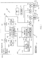
- FIG. 1 is a block schematic diagram of an example of a spacecraft in accordance with an embodiment of the present disclosure.
- FIGS. 2A and 2B are a flow chart of an example of a method for autonomously controlling electric power supplied to a thruster during electric orbit raising of a spacecraft in accordance with an embodiment of the present disclosure.
- FIG. 3 is an illustration of an example of electric orbit raising of a spacecraft in accordance with an embodiment of the present disclosure.
- FIG. 4 is an illustration of an eclipse during electric orbit raising of a spacecraft in accordance with an embodiment of the present disclosure.
- FIG. 5A is a graph illustrating an example of a state of charge (SOC) of a battery during electric orbit raising in accordance with an embodiment of the present disclosure.
- SOC state of charge
- FIG. 5B is a graph illustrating an example of an electric power level supplied to a thruster during electric orbit raising in accordance with an embodiment of the present disclosure.
- FIG. 6 is a table of an example of operating points of a power processing unit to supply power to an associated thruster in accordance with an embodiment of the present disclosure.
- FIG. 1 is a block schematic diagram of an example of a spacecraft 100 in accordance with an embodiment of the present disclosure.
- the spacecraft 100 is a satellite or other space vehicle or apparatus.
- the spacecraft 100 includes a system 102 for autonomously controlling electric power supplied to a thruster 104 of the spacecraft 100 during electric orbit raising.
- An example of electric orbit raising 300 is illustrated in FIG. 3 and is a procedure of transitioning the spacecraft 100 from a separation orbit 302 after separation from a launch vehicle 402 ( FIG. 4 ) to a target orbit 304 where the spacecraft 100 will operate.
- Electric orbit raising 300 includes a series of transition orbits or intermediate orbits 306 during which thrusters 104 are fired to move the spacecraft 100 to the target orbit 304 .
- a position 308 of the sun 410 ( FIG. 4 ) during electric orbit raising 300 is also illustrated in the example of FIG. 3 .
- the spacecraft 100 includes a plurality of thrusters 104 .
- the spacecraft 100 includes two thrusters 104 .
- the thrusters 104 are electric propulsion thrusters, such as Hall Effect thrusters (HET) or similar thrusters.
- the plurality of thrusters 104 are used for electric orbit raising 300 and station keeping when the spacecraft 100 reaches the target orbit 304 .
- the thrusters 104 use a propellant 106 to generate thrust 108 .
- the propellant 106 is stored in a tank 110 .
- the propellant 106 is Xenon gas.
- the propellant 106 is fed to the thrusters 104 by a feed system 112 .
- a propellant flow controller 114 such as a Xenon flow controller (XFC1 and XFC2), for example, is associated with each thruster 104 and operatively couples the feed system 112 to each thruster 104 .
- the amount of thrust 108 generated by each thruster 104 during firing is controlled by an amount of electric power 118 supplied to each thruster 104 and the amount of propellant 106 used during firing of each thruster 104 is determined by the amount of electric power 118 supplied.
- the amount of electric power 118 and propellant 106 used will also be dependent upon the duration of firing each time the thruster 104 is fired.
- a power processing unit (PPU) 120 is also associated with each thruster 104 to control an amount of electric power 118 or electric power level 152 supplied to each thruster 104 during firing.
- Each thruster 104 is mechanically coupled to an exterior 122 of the spacecraft 100 by a gimbaled platform mechanism 124 such as a Xenon gimbaled platform (GXP1 and GPX2) mechanism for example.
- the gimbaled platform mechanism 124 provides autonomous momentum dump capability by moving the thrust direction 116 to dump accumulated momentum due to center of gravity travel of the spacecraft 100 and thruster pointing.
- the spacecraft 100 also includes one or more solar arrays 126 operatively attached to the spacecraft 100 .
- the solar arrays 126 are configured to convert light energy to electric energy and provide electric power 130 to the components 127 of the spacecraft 100 .
- the spacecraft 100 includes a north solar array 126 a and a south solar array 126 b .
- the north solar array 126 a and the south solar array 126 b are mounted on opposite sides of the spacecraft 100 .
- the north solar array 126 a and the south solar array 126 b are electrically coupled to an integrated power controller (IPC) 128 .
- the IPC 128 receives electric power 130 from the solar arrays 126 and controls distribution of the electric power 130 to other components 127 of the spacecraft 100 .
- IPC integrated power controller
- the IPC 128 provides the electric power 130 to the power processing units 120 to operate the thrusters 104 via a 100 volt bus 132 .
- the IPC 128 also distributes electric power 130 to other components 127 of the spacecraft via a 30 volt bus 134 which is connected to secondary bus units 136 .
- the spacecraft 100 also includes a battery 138 to power the spacecraft 100 .
- the battery 138 is a battery pack.
- the spacecraft 100 further includes spacecraft control electronics (SCE) 140 powered by the battery 138 .
- the battery 138 is charged by electric power 130 from the solar arrays 126 through the IPC 128 .
- the IPC 128 controls charging of the battery 138 by the solar arrays 126 .
- a state of charge (SOC) 142 of the battery 138 is monitored by the spacecraft control electronics 140 . Voltages 144 associated with the battery are measured to determine the SOC 142 of the battery 138 at any time. Referring also to FIG. 5A , FIG.
- 5A is a graph 500 illustrating an example of a state of charge (SOC) 142 of a battery 138 during electric orbit raising 300 in accordance with an embodiment of the present disclosure.
- the horizontal axis is time measured in days and the vertical axis is battery SOC 142 measured in a percentage of charge of the battery 138 .
- the spacecraft control electronics 140 transmit control signals 146 to the IPC 128 to control charging the battery 138 in response to at least the SOC 142 of the battery 138 to maintain a SOC 142 of the battery 138 proximate a preset threshold 502 ( FIG. 5A ) or within predetermined limits.
- a preset threshold 502 FIG. 5A
- the preset threshold 502 is about 90% of a full charge of the battery 138 . In other examples or applications, the preset threshold 502 may be set at other preset threshold levels. Maintaining the SOC 142 of the battery 138 proximate the preset threshold 502 or within predetermined limits is also referred to as maintaining a balanced SOC 142 of the battery 308 .
- the spacecraft control electronics 140 include a processor 148 .
- the spacecraft control electronics 140 are configured to perform a set of functions 150 as described in more detail with reference to FIGS. 2A and 2B .
- the spacecraft control electronics 140 are configured to control operation of the thrusters 104 .
- FIG. 4 is an illustration of an eclipse 406 during electric orbit raising 300 of a spacecraft 100 in accordance with an embodiment of the present disclosure.
- the spacecraft control electronics 140 are also configured to determine the SOC 142 of the battery 138 onboard the spacecraft 100 at an entry 404 ( FIG. 4 ) into an eclipse 406 during each orbit 306 of a plurality of orbits 306 during the electric orbit raising 300 of the spacecraft 100 .
- the plurality of orbits 306 are also referred to as intermediate orbits.
- An eclipse 406 occurs during each orbit 306 when the earth 408 is between the spacecraft 100 and the sun 410 .
- the space craft control electronics 140 are also configured to determine an electric power level 152 used to fire each thruster 104 during each orbit 306 beginning after the eclipse 406 .
- the electric power level 152 is determined based on the SOC 142 of the battery 138 .
- the electric power level 152 supplied to each thruster 104 is also determined based on a particular electric power level 152 that will provide a shortest electric orbit raising 300 duration and minimize propellant 106 usage during the electric orbit raising 300 .
- FIG. 5B is a graph 508 illustrating an example of electric power level 152 supplied by a power processing unit 120 to an associated thruster 104 during electric orbit raising 300 to maximize thruster power and minimize electric orbit raising 300 in accordance with an embodiment of the present disclosure.
- the horizontal axis is time measured in days and the vertical axis is thruster command power measured in watts.
- the spacecraft control electronics 140 are additionally configured to balance the SOC 142 of the battery 138 for each orbit 306 by autonomously controlling the electric power level 152 supplied to each thruster 104 and autonomously controlling the timing during which each thruster 104 is fired during each orbit 306 of the electric orbit raising 300 .
- the spacecraft control electronics 140 are further configured to fire each thruster 104 during sun light and shut off each thruster 104 during the eclipse 406 of each orbit 306 of the plurality of orbits 306 during electric orbit raising 300 .
- the electric power level 152 used to fire each thruster 104 is determined by determining an electric power level 152 supplied to each thruster 104 by the power processing unit 120 associated with each thruster 104 .
- the electric power level 152 supplied by the power processing unit 120 to the associated thruster 104 is set based on matching a particular SOC 142 of the battery 138 to a corresponding one of a plurality of predefined operating points 602 ( FIG. 6 ) of the power processing unit 120 and the associated thruster 104 .
- the electric power level 152 supplied by the power processing unit 120 to the associated thruster 104 is set in steps to match the particular SOC 142 of the battery 138 to the corresponding one of the plurality of predefined operating points 602 of the power processing unit 120 and the associated thruster 104 .
- FIGS. 2A and 2B are a flow chart of an example of a method 200 for autonomously controlling electric power 118 supplied to a thruster 104 during electric orbit raising 300 ( FIG. 3 ) of a spacecraft 100 ( FIG. 1 ) in accordance with an embodiment of the present disclosure.
- the method 200 is embodied in and performed by the spacecraft control electronics 140 .
- a state of charge 142 of a battery 138 onboard the spacecraft 100 is determined at an entry 404 ( FIG. 4 ) into an eclipse 406 during each orbit 306 of a plurality of orbits 306 during the electric orbit raising 300 of the spacecraft 100 .
- an electric power level 152 is determined to use to fire each thruster 104 of a plurality of thrusters 104 during each orbit 306 beginning after the eclipse 406 , based at least on the state of charge 142 of the battery 138 , such that the determined electric power level 152 provides a shortest electric orbit raising 300 duration, and minimizes thruster propellant 106 usage during electric orbit raising 300 .
- the state of charge 142 of the battery 138 is balanced for each orbit 306 by autonomously controlling the electric power level 152 and timing during which each thruster 104 is fired during each orbit 306 of the electric orbit raising 300 .
- the state of charge 142 of the battery 138 is balanced by maintaining the state of charge 142 of the battery 138 proximate the preset threshold 502 ( FIG. 5A ) or within predetermined limits.
- the electric power level 152 used to fire each thruster 104 is autonomously controlled onboard the spacecraft 100 without control from a ground station 160 ( FIG. 1 ) or with minimal control from the ground station 160 .
- Determining the electric power level 152 used to fire each thruster 104 includes determining an electric power level 152 supplied to each thruster 104 by a power processing unit 120 associated with each thruster 104 .
- the electric power level 152 supplied by the power processing unit 120 to the associated thruster 104 is set based on matching a particular state of charge 142 of the battery 138 to a corresponding one of a plurality of predefined operating points 602 ( FIG. 6 ) of the associated thruster 104 .
- FIG. 6 is a table 600 of an example of a plurality of predefined operating points 602 of a power processing unit 120 and associated thruster 104 in accordance with an embodiment of the present disclosure.
- Each of the plurality of predefined operating points 602 of the power processing unit 120 and associated thruster 104 are defined by a group of parameters 604 which are supplied by the power processing unit 120 to the associated thruster 104 to control firing of the thruster 104 .
- the parameters 604 include but are not necessarily limited to a discharge power 604 a , a discharge voltage 604 b , a discharge current 604 c , and a magnetic current 604 d of the power processing unit 120 which is supplied to the associated thruster 104 .
- the electric power level 152 supplied by the power processing unit 120 to the associated thruster 104 is set in steps to match the particular state of charge 142 of the battery 138 to the corresponding one of the plurality of predefined operating points 602 ( FIG. 6 ) of the power processing unit 120 and the associated thruster 104 .
- a determination is made whether the state of charge 142 of the battery 138 is greater than or equal to a preset threshold, for example, the preset threshold 502 in FIG. 5 . If the state of charge 142 of the battery 138 is greater than or equal to the preset threshold 502 in block 206 , the method 200 advances to block 208 .
- the electric power level 152 supplied by the power processing unit 120 to the associate thruster 104 is set by adding a chosen number of power level steps to a base power level in response to the state of charge 142 of the battery 138 exceeding or being equal to a preset threshold 502 .
- the chosen number of power level steps is determined by matching the state of charge 142 of the battery 138 to a corresponding one of the plurality of predefined operating points 602 ( FIG. 6 ) of the power processing unit 120 and associated thruster 104 . This process maximizes the amount of thrust 108 produced by each thruster 104 each orbit 306 during electric orbit raising 300 to minimize the duration of electric orbit raising 300 and to conserve propellant 106 .
- the method 200 advances to block 210 .
- the electric power level 152 supplied by the power processing unit 120 to the associated thruster 104 is set by subtracting a chosen number of power level steps from a base power level in response to the state of charge 142 of the battery 138 being less than the preset threshold 502 .
- the chosen number of power level steps is determined by matching the state of charge 142 of the battery 138 to a corresponding one of the plurality of predefined operating points 602 of the power processing unit 120 and the associated thruster 104 .
- the processor 148 of the space craft control electronics 140 are configured to switch between the plurality of predefined operating points 602 of the power processing unit 120 and the associated thruster 104 to maintain a balanced state of charge 142 of the battery 138 .
- the balanced state of charge 142 of the battery 138 is maintained by keeping the state of charge 142 of the battery 138 proximate the preset threshold 502 .
- the plurality of predefined operating points 602 include a set of parameters 604 of the associated thruster 104 as previously described.
- the power processing unit 120 is also configured to provide fine control of a resolution of the discharge current 604 c supplied by the power processing unit 120 to the associated thruster 104 . Fine control includes adjusting the resolution of the discharge current 604 c by the power processing unit 120 to provide more precise control of the electric power 118 supplied by power processing unit 120 to the associated thruster 104 .
- a neutral power balance is maintained by adjusting thruster power settings to correspond to the electric power 130 generated by the solar arrays 126 minus electric power 130 consumed by loads, such as components 127 , and battery charging.
- the neutral power balance is defined as a balance between the amount of electric power 118 used to fire each of the thrusters 104 during each orbit 306 and the electric power 130 generated by the solar arrays 126 reduced by the electric power 130 consumed by loads, such as components 127 consuming electric power 130 , and also reduced by charging the battery 138 during each orbit 306 .
- thruster propellant 106 usage is minimized and the electric orbit raising 300 duration is minimized by switching between the predefined operating points 602 ( FIG. 6 ) of the power processing unit 120 and the associated thruster 104 to maintain the balanced state of charge 142 of the battery 138 .
- Available electric power 118 used to fire the thrusters 104 is maximized by maintaining the balanced state of charge 142 of the battery 142 . Maximizing the available electric power 118 used to fire the thruster 104 minimizes the electric orbit raising 300 duration and preserves propellant 106 for station keeping.
- each thruster 104 is fired during sun light and shut off during the eclipse 406 ( FIG. 4 ) of each orbit 306 of the plurality of orbits 306 during electric orbit raising 300 to minimize thruster propellant 106 usage and to minimize the electric orbit raising 300 duration.
- the operational thruster will be fired at maximum power continuously, including eclipses 406 , to minimize the electric orbit raising 300 duration.
- fault protection is performed in response to being unable to maintain a balanced state of charge 142 of the battery 138 .
- Fault protection prevents the battery 138 from discharging substantially completely.
- fault protection is a flight software (FSW) algorithm that is monitoring a spacecraft parameter, such a state of charge 142 of the battery 138 , and will trigger a response if the parameter exceeds or gets below a predetermined threshold(s).
- the fault response is a sequence of commands that are issued by the FSW to the spacecraft components, such as the power processing units 120 and the integrated power controller 128 , to prevent complete shutdown of the spacecraft components and to protect the spacecraft 100 .
- level 1 (or tier 1) fault protection will be triggered first, then if level 1 fault protection fails to correct the failure condition, level 2 (or tier 2) fault protection is triggered that usually have a more drastic response.
- the fault protection is embodied in and performed by the spacecraft electronics 140 .
- blocks 220 and 222 define two levels of fault protection.
- a level 1 fault protection is performed in response to the state of charge 142 of the battery 138 being below a first preset fault threshold 504 ( FIG. 5A ).
- the level 1 fault protection includes shutting down the power processing unit 120 associated with each thruster 104 .
- the first preset fault threshold 504 is slightly more than a 20% charge of the battery 138 or about 21% of a full or 100% charge of the battery 138 .
- a level 2 fault protection is performed in response to the state of charge 142 of the battery 138 falling below a second preset fault threshold 506 ( FIG. 5A ) that is lower than the first preset fault threshold 504 .
- the level 2 fault protection includes switching the integrated power controller (IPC) 128 ( FIG. 1 ) off in addition to shutting down the power processing unit 120 associated with each thruster 104 .
- the second preset fault threshold 506 is slightly less than a 20% charge of the battery 138 or about 19% of a full or 100% charge of the battery 138 .
- each block in the flowchart or block diagrams may represent a module, segment, or portion of instructions, which comprises one or more executable instructions for implementing the specified logical function(s).
- the functions noted in the block may occur out of the order noted in the figures.
- two blocks shown in succession may, in fact, be executed substantially concurrently, or the blocks may sometimes be executed in the reverse order, depending upon the functionality involved.
Abstract
Description
Claims (20)
Priority Applications (1)
| Application Number | Priority Date | Filing Date | Title |
|---|---|---|---|
| US16/227,719 US11401053B2 (en) | 2018-12-20 | 2018-12-20 | Autonomous control of electric power supplied to a thruster during electric orbit raising |
Applications Claiming Priority (1)
| Application Number | Priority Date | Filing Date | Title |
|---|---|---|---|
| US16/227,719 US11401053B2 (en) | 2018-12-20 | 2018-12-20 | Autonomous control of electric power supplied to a thruster during electric orbit raising |
Publications (2)
| Publication Number | Publication Date |
|---|---|
| US20200198807A1 US20200198807A1 (en) | 2020-06-25 |
| US11401053B2 true US11401053B2 (en) | 2022-08-02 |
Family
ID=71097093
Family Applications (1)
| Application Number | Title | Priority Date | Filing Date |
|---|---|---|---|
| US16/227,719 Active 2040-04-26 US11401053B2 (en) | 2018-12-20 | 2018-12-20 | Autonomous control of electric power supplied to a thruster during electric orbit raising |
Country Status (1)
| Country | Link |
|---|---|
| US (1) | US11401053B2 (en) |
Families Citing this family (5)
| Publication number | Priority date | Publication date | Assignee | Title |
|---|---|---|---|---|
| US11396388B2 (en) | 2018-12-20 | 2022-07-26 | The Boeing Company | Optimized power balanced variable thrust transfer orbits to minimize an electric orbit raising duration |
| US11753188B2 (en) | 2018-12-20 | 2023-09-12 | The Boeing Company | Optimized power balanced low thrust transfer orbits utilizing split thruster execution |
| GB2612359A (en) * | 2021-10-29 | 2023-05-03 | Iceye Oy | Satellite operation and processing of satellite state data |
| US11649072B1 (en) | 2022-05-05 | 2023-05-16 | Maxar Space Llc | Power processing unit (PPU) and electric propulsion system (EPS) for spacecraft |
| EP4299449A1 (en) | 2022-06-27 | 2024-01-03 | Airbus Defence and Space SAS | Method for controlling a plasma thruster |
Citations (63)
| Publication number | Priority date | Publication date | Assignee | Title |
|---|---|---|---|---|
| US4995216A (en) * | 1988-06-14 | 1991-02-26 | Ford New Holland, Inc. | Bale wrapping control apparatus for round balers |
| US5551218A (en) * | 1994-09-19 | 1996-09-03 | Gehl Company | Round baler monitoring and control system |
| US5557510A (en) * | 1993-11-29 | 1996-09-17 | Gehl Company | Control system for a large round baler |
| US5595360A (en) * | 1994-03-25 | 1997-01-21 | Hughes Aircraft Company | Optimal transfer orbit trajectory using electric propulsion |
| FR2743342A1 (en) * | 1996-01-05 | 1997-07-11 | Smh Management Services Ag | METHOD AND DEVICE FOR ADJUSTING THE DISTRIBUTION OF ELECTRIC POWER IN A MOTOR VEHICLE, IN PARTICULAR HYBRID PROPULSION |
| US5685505A (en) * | 1995-01-17 | 1997-11-11 | Meckler; Milton | Wave energy beaming and holograph tracking for power generating spacecraft platforms |
| US6031334A (en) * | 1998-06-17 | 2000-02-29 | Primex Technologies, Inc. | Method and apparatus for selectively distributing power in a thruster system |
| FR2785103A1 (en) * | 1998-10-23 | 2000-04-28 | Agence Spatiale Europeenne | Electrical energy generator for a regulated supply bus used onboard satellites, has three state regulators for solar cell modules |
| US6081710A (en) * | 1997-07-10 | 2000-06-27 | Globalstar L.P. | Dynamic traffic allocation for power control in multiple satellite communication systems |
| US6116543A (en) | 1996-04-05 | 2000-09-12 | Societe Nationale D'etude Et De Construction De Moteurs D'aviation | Method and a system for putting a space vehicle into orbit, using thrusters of high specific impulse |
| EP1059232A2 (en) * | 1999-06-09 | 2000-12-13 | Space Systems / Loral, Inc. | An orbit raising system and method for geosynchronous satellites |
| US6237876B1 (en) | 2000-07-28 | 2001-05-29 | Space Systems/Loral, Inc. | Methods for using satellite state vector prediction to provide three-axis satellite attitude control |
| US6341749B1 (en) * | 1998-09-25 | 2002-01-29 | Hughes Electronics Corporation | Method of simultaneously reducing inclination and eccentricity for geostationary orbit transfer |
| US6449936B1 (en) * | 2000-06-15 | 2002-09-17 | Deere & Company | Pick-up floatation suspension |
| US20030062452A1 (en) * | 2001-09-04 | 2003-04-03 | David Oh | Electric orbit raising with variable thrust |
| US20040083704A1 (en) * | 2002-10-24 | 2004-05-06 | Deere & Company, A Delaware Corporation | Crop recovery machine |
| US20040090195A1 (en) * | 2001-06-11 | 2004-05-13 | Motsenbocker Marvin A. | Efficient control, monitoring and energy devices for vehicles such as watercraft |
| US6755377B1 (en) * | 2001-03-07 | 2004-06-29 | Tether Applications, Inc. | Apparatus for observing and stabilizing electrodynamic tethers |
| US20040232878A1 (en) * | 2003-05-19 | 2004-11-25 | Couch Philip R. | Self-contained, renewable power supply and control system |
| US6845950B1 (en) | 2003-11-26 | 2005-01-25 | Lockheed Martin Corporation | System for high efficiency spacecraft orbit transfer |
| US6942186B1 (en) * | 2001-03-07 | 2005-09-13 | Star Technology And Research, Inc. | Method and apparatus for propulsion and power generation using spinning electrodynamic tethers |
| GB2413861A (en) * | 2004-05-06 | 2005-11-09 | Vega Group Plc | Controlling power to satellite electric propulsion system during eclipses. |
| US20060048481A1 (en) * | 2004-09-07 | 2006-03-09 | Hood William A | Method of initiating automatic feed of bale wrapping material |
| US7197979B2 (en) * | 2005-06-10 | 2007-04-03 | Deere & Company | Controlled bale ejection mechanism |
| US7246775B1 (en) * | 2004-08-02 | 2007-07-24 | Lockheed Martin Corporation | System and method of substantially autonomous geosynchronous time-optimal orbit transfer |
| US20090310391A1 (en) * | 2008-06-17 | 2009-12-17 | The Boeing Company | Solar array peak power extraction |
| US7640852B1 (en) * | 2008-11-21 | 2010-01-05 | Deere & Company | Round baler belt-tensioning cylinder arrangement also used for bale ejection |
| US7694504B1 (en) * | 2008-09-24 | 2010-04-13 | Deere & Company | Secondary feeder rotor behind undershot precutter |
| US20110073714A1 (en) * | 2009-09-29 | 2011-03-31 | Vladimir Hruby | Solar powered spacecraft power system for a hall effect thruster |
| US8056314B1 (en) * | 2010-12-03 | 2011-11-15 | Deere & Company | Wide crop pick-up having primary and secondary stripper plates for converging augers respectively mounted to movable crop guide plate portion and to fixed walls behind the augers |
| US20120097796A1 (en) * | 2010-10-20 | 2012-04-26 | Saghir Munir | Satellite orbit raising using electric propulsion |
| US20120097797A1 (en) * | 2010-10-20 | 2012-04-26 | Space Systems/Loral, Inc. | Spacecraft momentum management |
| RU2459749C1 (en) * | 2010-12-15 | 2012-08-27 | Открытое акционерное общество "Информационные спутниковые системы" имени академика М.Ф. Решетнева" | Method of producing space apparatus |
| US20120217348A1 (en) * | 2011-02-21 | 2012-08-30 | European Space Agency | Earth observation satellite, satellite system, and launching system for launching satellites |
| US8457810B1 (en) * | 2011-04-14 | 2013-06-04 | The Boeing Company | Compound steering law for efficient low thrust transfer orbit trajectory |
| RU2496690C1 (en) * | 2012-03-23 | 2013-10-27 | Открытое акционерное общество "Информационные спутниковые системы" имени академика М.Ф. Решетнева" | Method of constructing spacecraft |
| WO2014021363A1 (en) * | 2012-08-02 | 2014-02-06 | 日産自動車株式会社 | Charging management system for unpiloted conveyance vehicle and charging management method |
| US20140061386A1 (en) * | 2012-05-11 | 2014-03-06 | The Boeing Company | Methods and apparatus for performing propulsion operations using electric propulsion systems |
| US20140109164A1 (en) * | 2011-06-06 | 2014-04-17 | Sony Corporation | Reception apparatus and method, information delivery apparatus and method, and information delivery system |
| US8763957B1 (en) * | 2012-10-08 | 2014-07-01 | Space Systems/Loral, Llc | Spacecraft transfer orbit techniques |
| US8930048B1 (en) * | 2011-04-14 | 2015-01-06 | The Boeing Company | Enhanced compound steering law for general low thrust mission |
| RU2541512C2 (en) * | 2013-03-26 | 2015-02-20 | Открытое акционерное общество "Информационные спутниковые системы" имени академика М.Ф. Решётнева" | Method to control autonomous system of spacecraft power supply |
| KR20150031329A (en) * | 2012-08-02 | 2015-03-23 | 닛산 지도우샤 가부시키가이샤 | Battery unit for unpiloted conveyance vehicles |
| US20150134175A1 (en) * | 2013-11-11 | 2015-05-14 | Deere & Company | Location-based material gathering |
| WO2015075566A1 (en) * | 2013-11-20 | 2015-05-28 | Blacklight Power, Inc. | Power generation systems and methods regarding same |
| US20150156842A1 (en) * | 2012-06-11 | 2015-06-04 | Elm Inc. | High-stability dimmer |
| WO2015130950A2 (en) * | 2014-02-26 | 2015-09-03 | Clark Emerson Cohen | An improved performance and cost global navigation satellite system architecture |
| US20160050851A1 (en) * | 2014-08-25 | 2016-02-25 | Deere & Company | Bale orientation control system and method for agricultural round baler |
| RU2585171C1 (en) * | 2014-12-31 | 2016-05-27 | Российская Федерация, от имени которой выступает Министерство обороны Российской Федерации | Method for operating nickel-hydrogen batteries of modular power supply system (versions) |
| RU2586172C2 (en) * | 2014-08-13 | 2016-06-10 | Российская Федерация, от имени которой выступает Федеральное космическое агентство | Method of controlling parameters of nickel-hydrogen accumulator batteries in power supply system of spacecraft (versions) |
| US20160165803A1 (en) * | 2014-12-11 | 2016-06-16 | Cnh Industrial America Llc | Adjusting bale density setting based on bale weight and/or moisture |
| US20160251092A1 (en) * | 2015-02-26 | 2016-09-01 | Spire Global, Inc. | System and method for power distribution in a autonomous modular system |
| US20160355292A1 (en) * | 2015-06-03 | 2016-12-08 | Deere & Company | Module wrap feed system |
| US20160368624A1 (en) * | 2015-06-16 | 2016-12-22 | Busek Co., Inc. | Geosat propulsion system architecture with electric apogee motor |
| US20170049058A1 (en) * | 2015-08-17 | 2017-02-23 | Deere & Company | Motor-drive for application of wrap material to crop packages |
| RU2611568C1 (en) * | 2016-01-12 | 2017-02-28 | Российская Федерация, от имени которой выступает Федеральное космическое агентство | Method of nickel-hydrogen accumulator batteries operation in power supply system of spacecraft with large service life |
| RU2621694C2 (en) * | 2015-07-01 | 2017-06-07 | Российская Федерация, от имени которой выступает Министерство обороны Российской Федерации | Method for operating nickel-hydrogen accumulator batteries of aircraft electric power system |
| US20170287303A1 (en) * | 2016-04-05 | 2017-10-05 | Deere & Company | System and method for marking and identifying baled crop |
| US20170332556A1 (en) * | 2014-12-02 | 2017-11-23 | Mchale Engineering | Continuous Round Baler |
| RU2661187C1 (en) * | 2017-07-17 | 2018-07-12 | Российская Федерация, от имени которой выступает Министерство обороны Российской Федерации | Method of ground environment of spacecraft power supply system accumulator batteries |
| EP3670360A1 (en) * | 2018-12-20 | 2020-06-24 | The Boeing Company | Optimized power balanced low thrust transfer orbits utilizing split thruster execution |
| EP3672018A1 (en) * | 2018-12-20 | 2020-06-24 | The Boeing Company | Autonomous control of electric power consumption by an apparatus |
| US20200198810A1 (en) | 2018-12-20 | 2020-06-25 | The Boeing Company | Optimized power balanced variable thrust transfer orbits to minimize an electric orbit raising duration |
-
2018
- 2018-12-20 US US16/227,719 patent/US11401053B2/en active Active
Patent Citations (79)
| Publication number | Priority date | Publication date | Assignee | Title |
|---|---|---|---|---|
| US4995216A (en) * | 1988-06-14 | 1991-02-26 | Ford New Holland, Inc. | Bale wrapping control apparatus for round balers |
| US5557510A (en) * | 1993-11-29 | 1996-09-17 | Gehl Company | Control system for a large round baler |
| US5716029A (en) * | 1994-03-25 | 1998-02-10 | Hughes Electronics | Constant sun angle transfer orbit sequence and method using electric propulsion |
| US5595360A (en) * | 1994-03-25 | 1997-01-21 | Hughes Aircraft Company | Optimal transfer orbit trajectory using electric propulsion |
| US5551218A (en) * | 1994-09-19 | 1996-09-03 | Gehl Company | Round baler monitoring and control system |
| US5685505A (en) * | 1995-01-17 | 1997-11-11 | Meckler; Milton | Wave energy beaming and holograph tracking for power generating spacecraft platforms |
| FR2743342A1 (en) * | 1996-01-05 | 1997-07-11 | Smh Management Services Ag | METHOD AND DEVICE FOR ADJUSTING THE DISTRIBUTION OF ELECTRIC POWER IN A MOTOR VEHICLE, IN PARTICULAR HYBRID PROPULSION |
| US5847520A (en) * | 1996-01-05 | 1998-12-08 | Smh Management Services Ag | Method and apparatus for adjusting the electric power distribution in a motor vehicle, in patricular a hybrid-powered vehicle |
| US6116543A (en) | 1996-04-05 | 2000-09-12 | Societe Nationale D'etude Et De Construction De Moteurs D'aviation | Method and a system for putting a space vehicle into orbit, using thrusters of high specific impulse |
| US6081710A (en) * | 1997-07-10 | 2000-06-27 | Globalstar L.P. | Dynamic traffic allocation for power control in multiple satellite communication systems |
| US6031334A (en) * | 1998-06-17 | 2000-02-29 | Primex Technologies, Inc. | Method and apparatus for selectively distributing power in a thruster system |
| US6341749B1 (en) * | 1998-09-25 | 2002-01-29 | Hughes Electronics Corporation | Method of simultaneously reducing inclination and eccentricity for geostationary orbit transfer |
| FR2785103A1 (en) * | 1998-10-23 | 2000-04-28 | Agence Spatiale Europeenne | Electrical energy generator for a regulated supply bus used onboard satellites, has three state regulators for solar cell modules |
| US6181115B1 (en) * | 1998-10-23 | 2001-01-30 | Agence Spatiale Europeenne | Device for generating electrical energy for a power supply bus |
| US7113851B1 (en) * | 1999-06-09 | 2006-09-26 | Walter Gelon | Practical orbit raising system and method for geosynchronous satellites |
| EP1059232A2 (en) * | 1999-06-09 | 2000-12-13 | Space Systems / Loral, Inc. | An orbit raising system and method for geosynchronous satellites |
| US6449936B1 (en) * | 2000-06-15 | 2002-09-17 | Deere & Company | Pick-up floatation suspension |
| US6237876B1 (en) | 2000-07-28 | 2001-05-29 | Space Systems/Loral, Inc. | Methods for using satellite state vector prediction to provide three-axis satellite attitude control |
| US6755377B1 (en) * | 2001-03-07 | 2004-06-29 | Tether Applications, Inc. | Apparatus for observing and stabilizing electrodynamic tethers |
| US6942186B1 (en) * | 2001-03-07 | 2005-09-13 | Star Technology And Research, Inc. | Method and apparatus for propulsion and power generation using spinning electrodynamic tethers |
| US20040090195A1 (en) * | 2001-06-11 | 2004-05-13 | Motsenbocker Marvin A. | Efficient control, monitoring and energy devices for vehicles such as watercraft |
| US20030062452A1 (en) * | 2001-09-04 | 2003-04-03 | David Oh | Electric orbit raising with variable thrust |
| US6543723B1 (en) | 2001-09-04 | 2003-04-08 | Space Systems/Loral, Inc. | Electric orbit raising with variable thrust |
| US20040083704A1 (en) * | 2002-10-24 | 2004-05-06 | Deere & Company, A Delaware Corporation | Crop recovery machine |
| US20040232878A1 (en) * | 2003-05-19 | 2004-11-25 | Couch Philip R. | Self-contained, renewable power supply and control system |
| US6845950B1 (en) | 2003-11-26 | 2005-01-25 | Lockheed Martin Corporation | System for high efficiency spacecraft orbit transfer |
| GB2413861A (en) * | 2004-05-06 | 2005-11-09 | Vega Group Plc | Controlling power to satellite electric propulsion system during eclipses. |
| US7246775B1 (en) * | 2004-08-02 | 2007-07-24 | Lockheed Martin Corporation | System and method of substantially autonomous geosynchronous time-optimal orbit transfer |
| US20060048481A1 (en) * | 2004-09-07 | 2006-03-09 | Hood William A | Method of initiating automatic feed of bale wrapping material |
| US7197979B2 (en) * | 2005-06-10 | 2007-04-03 | Deere & Company | Controlled bale ejection mechanism |
| US8152108B2 (en) * | 2008-06-17 | 2012-04-10 | The Boeing Company | Solar array peak power extraction |
| US20090310391A1 (en) * | 2008-06-17 | 2009-12-17 | The Boeing Company | Solar array peak power extraction |
| WO2009155158A1 (en) * | 2008-06-17 | 2009-12-23 | The Boeing Company | Solar array peak power extraction |
| US7694504B1 (en) * | 2008-09-24 | 2010-04-13 | Deere & Company | Secondary feeder rotor behind undershot precutter |
| US7640852B1 (en) * | 2008-11-21 | 2010-01-05 | Deere & Company | Round baler belt-tensioning cylinder arrangement also used for bale ejection |
| US20110073714A1 (en) * | 2009-09-29 | 2011-03-31 | Vladimir Hruby | Solar powered spacecraft power system for a hall effect thruster |
| US20120097797A1 (en) * | 2010-10-20 | 2012-04-26 | Space Systems/Loral, Inc. | Spacecraft momentum management |
| US20120097796A1 (en) * | 2010-10-20 | 2012-04-26 | Saghir Munir | Satellite orbit raising using electric propulsion |
| US9108748B2 (en) | 2010-10-20 | 2015-08-18 | Space Systems/Loral, Llc | Satellite orbit raising using electric propulsion |
| US8056314B1 (en) * | 2010-12-03 | 2011-11-15 | Deere & Company | Wide crop pick-up having primary and secondary stripper plates for converging augers respectively mounted to movable crop guide plate portion and to fixed walls behind the augers |
| RU2459749C1 (en) * | 2010-12-15 | 2012-08-27 | Открытое акционерное общество "Информационные спутниковые системы" имени академика М.Ф. Решетнева" | Method of producing space apparatus |
| US20120217348A1 (en) * | 2011-02-21 | 2012-08-30 | European Space Agency | Earth observation satellite, satellite system, and launching system for launching satellites |
| US8930048B1 (en) * | 2011-04-14 | 2015-01-06 | The Boeing Company | Enhanced compound steering law for general low thrust mission |
| US8457810B1 (en) * | 2011-04-14 | 2013-06-04 | The Boeing Company | Compound steering law for efficient low thrust transfer orbit trajectory |
| US20140109164A1 (en) * | 2011-06-06 | 2014-04-17 | Sony Corporation | Reception apparatus and method, information delivery apparatus and method, and information delivery system |
| RU2496690C1 (en) * | 2012-03-23 | 2013-10-27 | Открытое акционерное общество "Информационные спутниковые системы" имени академика М.Ф. Решетнева" | Method of constructing spacecraft |
| US20140061386A1 (en) * | 2012-05-11 | 2014-03-06 | The Boeing Company | Methods and apparatus for performing propulsion operations using electric propulsion systems |
| US20150156842A1 (en) * | 2012-06-11 | 2015-06-04 | Elm Inc. | High-stability dimmer |
| KR20150031329A (en) * | 2012-08-02 | 2015-03-23 | 닛산 지도우샤 가부시키가이샤 | Battery unit for unpiloted conveyance vehicles |
| WO2014021363A1 (en) * | 2012-08-02 | 2014-02-06 | 日産自動車株式会社 | Charging management system for unpiloted conveyance vehicle and charging management method |
| US8763957B1 (en) * | 2012-10-08 | 2014-07-01 | Space Systems/Loral, Llc | Spacecraft transfer orbit techniques |
| RU2541512C2 (en) * | 2013-03-26 | 2015-02-20 | Открытое акционерное общество "Информационные спутниковые системы" имени академика М.Ф. Решётнева" | Method to control autonomous system of spacecraft power supply |
| US20150134175A1 (en) * | 2013-11-11 | 2015-05-14 | Deere & Company | Location-based material gathering |
| US20160290223A1 (en) * | 2013-11-20 | 2016-10-06 | Brilliant Light Power, Inc. | Power generation systems and methods regarding same |
| WO2015075566A1 (en) * | 2013-11-20 | 2015-05-28 | Blacklight Power, Inc. | Power generation systems and methods regarding same |
| EP3110695A2 (en) * | 2014-02-26 | 2017-01-04 | Clark Emerson Cohen | An improved performance and cost global navigation satellite system architecture |
| KR20160147724A (en) * | 2014-02-26 | 2016-12-23 | 클라크 에머슨 코헨 | An improved performance and cost global navigation satellite system architecture |
| US20160011318A1 (en) * | 2014-02-26 | 2016-01-14 | Clark Emerson Cohen | Performance and Cost Global Navigation Satellite System Architecture |
| CA2940652A1 (en) * | 2014-02-26 | 2015-09-03 | Clark Emerson Cohen | An improved performance and cost global navigation satellite system architecture |
| AU2015222926A1 (en) * | 2014-02-26 | 2016-10-13 | Clark Emerson Cohen | An improved performance and cost Global Navigation Satellite System architecture |
| WO2015130950A2 (en) * | 2014-02-26 | 2015-09-03 | Clark Emerson Cohen | An improved performance and cost global navigation satellite system architecture |
| RU2586172C2 (en) * | 2014-08-13 | 2016-06-10 | Российская Федерация, от имени которой выступает Федеральное космическое агентство | Method of controlling parameters of nickel-hydrogen accumulator batteries in power supply system of spacecraft (versions) |
| US20160050851A1 (en) * | 2014-08-25 | 2016-02-25 | Deere & Company | Bale orientation control system and method for agricultural round baler |
| US20170332556A1 (en) * | 2014-12-02 | 2017-11-23 | Mchale Engineering | Continuous Round Baler |
| US20160165803A1 (en) * | 2014-12-11 | 2016-06-16 | Cnh Industrial America Llc | Adjusting bale density setting based on bale weight and/or moisture |
| RU2585171C1 (en) * | 2014-12-31 | 2016-05-27 | Российская Федерация, от имени которой выступает Министерство обороны Российской Федерации | Method for operating nickel-hydrogen batteries of modular power supply system (versions) |
| US20160251092A1 (en) * | 2015-02-26 | 2016-09-01 | Spire Global, Inc. | System and method for power distribution in a autonomous modular system |
| US20160355292A1 (en) * | 2015-06-03 | 2016-12-08 | Deere & Company | Module wrap feed system |
| US20160368624A1 (en) * | 2015-06-16 | 2016-12-22 | Busek Co., Inc. | Geosat propulsion system architecture with electric apogee motor |
| RU2621694C2 (en) * | 2015-07-01 | 2017-06-07 | Российская Федерация, от имени которой выступает Министерство обороны Российской Федерации | Method for operating nickel-hydrogen accumulator batteries of aircraft electric power system |
| US20170049058A1 (en) * | 2015-08-17 | 2017-02-23 | Deere & Company | Motor-drive for application of wrap material to crop packages |
| RU2611568C1 (en) * | 2016-01-12 | 2017-02-28 | Российская Федерация, от имени которой выступает Федеральное космическое агентство | Method of nickel-hydrogen accumulator batteries operation in power supply system of spacecraft with large service life |
| US20170287303A1 (en) * | 2016-04-05 | 2017-10-05 | Deere & Company | System and method for marking and identifying baled crop |
| RU2661187C1 (en) * | 2017-07-17 | 2018-07-12 | Российская Федерация, от имени которой выступает Министерство обороны Российской Федерации | Method of ground environment of spacecraft power supply system accumulator batteries |
| EP3670360A1 (en) * | 2018-12-20 | 2020-06-24 | The Boeing Company | Optimized power balanced low thrust transfer orbits utilizing split thruster execution |
| EP3672018A1 (en) * | 2018-12-20 | 2020-06-24 | The Boeing Company | Autonomous control of electric power consumption by an apparatus |
| US20200198808A1 (en) | 2018-12-20 | 2020-06-25 | The Boeing Company | Optimized power balanced low thrust transfer orbits utilizing split thruster execution |
| US20200198810A1 (en) | 2018-12-20 | 2020-06-25 | The Boeing Company | Optimized power balanced variable thrust transfer orbits to minimize an electric orbit raising duration |
| US20200198811A1 (en) | 2018-12-20 | 2020-06-25 | The Boeing Company | Autonomous control of electric power consumption by an apparatus |
Non-Patent Citations (7)
| Title |
|---|
| Chetty, P.R.K. et al. "Topex Electrical Power System," Aerospace Power Systems, Proceedings of the Intersociety Energy Conversion Engineering Conference, IEEE, Boston, Aug. 4-9, 1991, pp. 36-44. |
| European Office Action dated Apr. 29, 2022, for European Patent Application No. 19202923.9, 7 pages. |
| Extended European Search Report dated May 18, 2020 for European Patent Application No. 19210308.3, 9 pages. |
| Extended European Search Report dated May 18, 2020 for European Patent Application No. 19217666.7, 6 pages. |
| Extended European Search Report dated May 4, 2020 for European Patent Application No. 19202923.9, 10 pages. |
| Kimbrel, Michael S. "Optimization of Electric Propulsion Orbit Raising" (Jun. 2002), Massachusetts Institute of Technology, Department of Aeronautics and Astronautics, retrieved from the Internet at: https://dspace.mit.edu/handle/1721.1/82240, 102 pages. |
| Shaff, Sven et al., "Advanced Electric Orbit-Raising Optimization for Operational Purpose" (2015), Astos Solutions GmbH, retrieved from the Internet at: https://www.astos.de/resources?query_string=downloads, 13 pages. |
Also Published As
| Publication number | Publication date |
|---|---|
| US20200198807A1 (en) | 2020-06-25 |
Similar Documents
| Publication | Publication Date | Title |
|---|---|---|
| US11401053B2 (en) | Autonomous control of electric power supplied to a thruster during electric orbit raising | |
| US11753188B2 (en) | Optimized power balanced low thrust transfer orbits utilizing split thruster execution | |
| US11396388B2 (en) | Optimized power balanced variable thrust transfer orbits to minimize an electric orbit raising duration | |
| US7922124B2 (en) | Power optimized system for electric propulsion stationkeeping geosynchronous spacecraft | |
| US20230211895A1 (en) | Method for optimising the orbital transfer of an electrically propelled spacecraft, and satellite using said method | |
| Jameson-Silva et al. | Adaptability of the SSL electric propulsion-140 subsystem for use on a NASA discovery class missions: psyche | |
| EP3482075B1 (en) | Arcjet propulsion systems for spacecraft and related method | |
| Nishiyama et al. | Hayabusa's way back to Earth by microwave discharge ion engines | |
| JP6541880B2 (en) | Satellite and thrust balance adjustment method | |
| Herman et al. | Life with a weak Heart; Prolonging the Grace Mission despite degraded Batteries | |
| Kuninaka et al. | Flight status of cathode-less microwave discharge ion engines onboard HAYABUSA asteroid explorer | |
| Milligan et al. | SMART-1 electric propulsion: an operational perspective | |
| Milligan et al. | SMART1 Electric Propulsion Operations | |
| US20170305579A1 (en) | Power architecture for solar electric propulsion applications | |
| CN114987803A (en) | Spacecraft angular momentum control method and system | |
| Renault et al. | Electric propulsion on ARTEMIS: a development status | |
| Gray et al. | Inmarsat 4F1 plasma propulsion system initial flight operations | |
| Ozaki et al. | In Orbit Operation of 20 mN Class Xenon Ion Engine for ETS-VIII | |
| Gray et al. | Flexible Operations of the Bepicolombo Electric Propulsion System | |
| EP3670361B1 (en) | Method and power supply system for providing electric energy in a flight vehicle | |
| Ceccanti et al. | Earth observation from elliptical orbits with very low altitude perigee | |
| Anshakov et al. | Mathematical models of station keeping for low orbit spacecraft with electric propulsion and limited power supply | |
| Gerard et al. | Eurostar E3000 in-flight experience | |
| JP2018530475A (en) | Propulsion system with differential throttling of electric thrusters | |
| Amorosi | Ion Propulsion System Saves ARTEMIS Satellite |
Legal Events
| Date | Code | Title | Description |
|---|---|---|---|
| AS | Assignment |
Owner name: THE BOEING COMPANY, ILLINOIS Free format text: ASSIGNMENT OF ASSIGNORS INTEREST;ASSIGNORS:MANSOUR, SADEK W.;NOEL, JEFFREY SCOTT;PIO RODA, RAINIER;SIGNING DATES FROM 20181127 TO 20181204;REEL/FRAME:047834/0243 |
|
| FEPP | Fee payment procedure |
Free format text: ENTITY STATUS SET TO UNDISCOUNTED (ORIGINAL EVENT CODE: BIG.); ENTITY STATUS OF PATENT OWNER: LARGE ENTITY |
|
| STPP | Information on status: patent application and granting procedure in general |
Free format text: NON FINAL ACTION MAILED |
|
| STPP | Information on status: patent application and granting procedure in general |
Free format text: RESPONSE TO NON-FINAL OFFICE ACTION ENTERED AND FORWARDED TO EXAMINER |
|
| STPP | Information on status: patent application and granting procedure in general |
Free format text: NOTICE OF ALLOWANCE MAILED -- APPLICATION RECEIVED IN OFFICE OF PUBLICATIONS |
|
| STPP | Information on status: patent application and granting procedure in general |
Free format text: PUBLICATIONS -- ISSUE FEE PAYMENT VERIFIED |
|
| STCF | Information on status: patent grant |
Free format text: PATENTED CASE |
|
| STPP | Information on status: patent application and granting procedure in general |
Free format text: WITHDRAW FROM ISSUE AWAITING ACTION |
|
| STPP | Information on status: patent application and granting procedure in general |
Free format text: DOCKETED NEW CASE - READY FOR EXAMINATION |
|
| STPP | Information on status: patent application and granting procedure in general |
Free format text: NOTICE OF ALLOWANCE MAILED -- APPLICATION RECEIVED IN OFFICE OF PUBLICATIONS |
|
| STPP | Information on status: patent application and granting procedure in general |
Free format text: AWAITING TC RESP., ISSUE FEE NOT PAID |
|
| STPP | Information on status: patent application and granting procedure in general |
Free format text: PUBLICATIONS -- ISSUE FEE PAYMENT VERIFIED |
|
| STCF | Information on status: patent grant |
Free format text: PATENTED CASE |