EP0780816B1 - Vorrichtung zum Erfassen der Anwesenheit und Geschwindigkeit eines Aufzeichnungsmediums - Google Patents
Vorrichtung zum Erfassen der Anwesenheit und Geschwindigkeit eines Aufzeichnungsmediums Download PDFInfo
- Publication number
- EP0780816B1 EP0780816B1 EP96309257.2A EP96309257A EP0780816B1 EP 0780816 B1 EP0780816 B1 EP 0780816B1 EP 96309257 A EP96309257 A EP 96309257A EP 0780816 B1 EP0780816 B1 EP 0780816B1
- Authority
- EP
- European Patent Office
- Prior art keywords
- record medium
- feed path
- roller means
- speed
- pulses
- Prior art date
- Legal status (The legal status is an assumption and is not a legal conclusion. Google has not performed a legal analysis and makes no representation as to the accuracy of the status listed.)
- Expired - Lifetime
Links
- 230000004044 response Effects 0.000 claims description 7
- 238000000034 method Methods 0.000 claims description 5
- 230000007246 mechanism Effects 0.000 description 10
- 230000009471 action Effects 0.000 description 3
- 230000003287 optical effect Effects 0.000 description 2
- 230000003466 anti-cipated effect Effects 0.000 description 1
- 238000010276 construction Methods 0.000 description 1
- 238000010586 diagram Methods 0.000 description 1
- 210000003195 fascia Anatomy 0.000 description 1
- 239000011159 matrix material Substances 0.000 description 1
- 230000008569 process Effects 0.000 description 1
- 238000011084 recovery Methods 0.000 description 1
- 230000008439 repair process Effects 0.000 description 1
Images
Classifications
-
- G—PHYSICS
- G07—CHECKING-DEVICES
- G07F—COIN-FREED OR LIKE APPARATUS
- G07F19/00—Complete banking systems; Coded card-freed arrangements adapted for dispensing or receiving monies or the like and posting such transactions to existing accounts, e.g. automatic teller machines
- G07F19/20—Automatic teller machines [ATMs]
-
- B—PERFORMING OPERATIONS; TRANSPORTING
- B65—CONVEYING; PACKING; STORING; HANDLING THIN OR FILAMENTARY MATERIAL
- B65H—HANDLING THIN OR FILAMENTARY MATERIAL, e.g. SHEETS, WEBS, CABLES
- B65H26/00—Warning or safety devices, e.g. automatic fault detectors, stop-motions, for web-advancing mechanisms
- B65H26/02—Warning or safety devices, e.g. automatic fault detectors, stop-motions, for web-advancing mechanisms responsive to presence of irregularities in running webs
-
- G—PHYSICS
- G07—CHECKING-DEVICES
- G07F—COIN-FREED OR LIKE APPARATUS
- G07F19/00—Complete banking systems; Coded card-freed arrangements adapted for dispensing or receiving monies or the like and posting such transactions to existing accounts, e.g. automatic teller machines
- G07F19/20—Automatic teller machines [ATMs]
- G07F19/201—Accessories of ATMs
-
- G—PHYSICS
- G07—CHECKING-DEVICES
- G07G—REGISTERING THE RECEIPT OF CASH, VALUABLES, OR TOKENS
- G07G5/00—Receipt-giving machines
-
- B—PERFORMING OPERATIONS; TRANSPORTING
- B65—CONVEYING; PACKING; STORING; HANDLING THIN OR FILAMENTARY MATERIAL
- B65H—HANDLING THIN OR FILAMENTARY MATERIAL, e.g. SHEETS, WEBS, CABLES
- B65H2220/00—Function indicators
- B65H2220/01—Function indicators indicating an entity as a function of which control, adjustment or change is performed, i.e. input
-
- B—PERFORMING OPERATIONS; TRANSPORTING
- B65—CONVEYING; PACKING; STORING; HANDLING THIN OR FILAMENTARY MATERIAL
- B65H—HANDLING THIN OR FILAMENTARY MATERIAL, e.g. SHEETS, WEBS, CABLES
- B65H2511/00—Dimensions; Position; Numbers; Identification; Occurrences
- B65H2511/50—Occurence
- B65H2511/51—Presence
-
- B—PERFORMING OPERATIONS; TRANSPORTING
- B65—CONVEYING; PACKING; STORING; HANDLING THIN OR FILAMENTARY MATERIAL
- B65H—HANDLING THIN OR FILAMENTARY MATERIAL, e.g. SHEETS, WEBS, CABLES
- B65H2511/00—Dimensions; Position; Numbers; Identification; Occurrences
- B65H2511/50—Occurence
- B65H2511/515—Absence
-
- B—PERFORMING OPERATIONS; TRANSPORTING
- B65—CONVEYING; PACKING; STORING; HANDLING THIN OR FILAMENTARY MATERIAL
- B65H—HANDLING THIN OR FILAMENTARY MATERIAL, e.g. SHEETS, WEBS, CABLES
- B65H2513/00—Dynamic entities; Timing aspects
- B65H2513/10—Speed
-
- B—PERFORMING OPERATIONS; TRANSPORTING
- B65—CONVEYING; PACKING; STORING; HANDLING THIN OR FILAMENTARY MATERIAL
- B65H—HANDLING THIN OR FILAMENTARY MATERIAL, e.g. SHEETS, WEBS, CABLES
- B65H2553/00—Sensing or detecting means
- B65H2553/40—Sensing or detecting means using optical, e.g. photographic, elements
- B65H2553/41—Photoelectric detectors
- B65H2553/412—Photoelectric detectors in barrier arrangements, i.e. emitter facing a receptor element
-
- B—PERFORMING OPERATIONS; TRANSPORTING
- B65—CONVEYING; PACKING; STORING; HANDLING THIN OR FILAMENTARY MATERIAL
- B65H—HANDLING THIN OR FILAMENTARY MATERIAL, e.g. SHEETS, WEBS, CABLES
- B65H2701/00—Handled material; Storage means
- B65H2701/10—Handled articles or webs
- B65H2701/19—Specific article or web
- B65H2701/1936—Tickets or coupons
Definitions
- the present invention relates to an apparatus for detecting the presence of a record medium, and more particularly relates to such an apparatus in which both the presence of the record medium is detected and the speed of motion of the record medium is measured during the passage of the record medium along a feed path (which may be formed by drive belts or rollers).
- a machine for controlling the movement whilst printing of a medium is disclosed in EP-A-0.376.576 .
- the speed of feeding of the medium is controlled to be uniform to synchronize with the operation of the printer.
- the apparatus which is the subject of the present invention may be employed in a variety of applications in which it is desired to detect the presence and speed of motion of record media as said media traverse a feed path.
- One such application is in a printer module which is employed in automated teller machines (ATMs) widely used by financial institutions such as banks.
- ATMs automated teller machines
- the printer module is capable of printing an account balance or a receipt of an ATM transaction, for a customer who uses the ATM.
- the printer module prints, say a transaction receipt, on a continuous roll of paper and cuts the paper to size after the receipt is printed.
- the receipt is then transported to a receipt slot in the front fascia of the ATM for collection by the user of the ATM.
- the continuous roll of receipt paper is mounted on a spindle the ends of which are each received in a recess in the printer.
- the leading portion of the roll of paper is received by feed means which transport this portion of the paper, extending from the paper roll, through a dot matrix printer which prints text on the paper a dot line at a time, the paper being advanced a predetermined distance between each dot line.
- feed means which transport this portion of the paper, extending from the paper roll, through a dot matrix printer which prints text on the paper a dot line at a time, the paper being advanced a predetermined distance between each dot line.
- an apparatus for detecting the presence of a record medium in a feed path and for sensing the speed of said record medium as it passes along said feed path characterized by roller means moveable between a first position when said record medium is not present in said feed path and a second position when said record medium is passing along said feed path, said roller means being arranged to be rotated by virtue of engagement with said record medium when in said second position, sensing means operative to provide an indication of the absence of said record medium when said roller means is in said first position, pulse generating means arranged to generate a series of pulses in response to rotation of said roller means, and electronic control means responsive to the pulses generated by said pulse generating means and arranged to make a determination of the speed of said record medium as it passes along said feed path.
- a method for detecting the presence of a record medium in a feed path and for sensing the speed of said record medium as it passes along said feed path characterized by the steps of: providing roller means moveable between a first position when said record medium is not present in said feed path and a second position when said record medium is passing along said feed path, said roller means being arranged to be rotated by virtue of engagement with said record medium when in said second position; indicating the absence of said record medium when said roller means is in said first position; generating a series of pulses in response to rotation of said roller means, and determining the speed of said record medium as it passes along said feed path in response to the pulses generated.
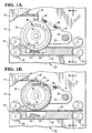
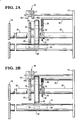
- Figs 1 and 2 include a partial showing of frame members 10 and 12 of a media transportation mechanism indicated generally by the reference numeral 14, and forming part of a printer.
- the aforementioned media transportation mechanism 14 includes feed rollers 16 (omitted from Fig. 2 for the sake of clarity) and guide means 20 located adjacent the feed rollers 16, to form a feed path 22 through the media transportation mechanism 14.
- a media presence detector in the form of a microswitch 24 is located in a recess 26 in the guide means 20.
- roller 28 Positioned above the recess 26 in the guide means 20, as viewed in Figs 1 and 2 , is a roller 28 which is of plastic construction.
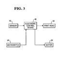
- the roller 28 is not driven by the motor 29 ( Fig. 3 ) which powers the drive rollers 16 in the transportation mechanism 14. Instead, the roller 28, which is rotatably mounted on a shaft 30, rotates under the influence of a record medium 31 transported along the feed path 22 so as to engage the roller 28, as illustrated in Figs 1B and 2B .
- the record medium 31 is a leading portion of a paper roll (not shown), the record medium 31 being driven by the feed rollers 16 in the direction of the arrow A towards a printhead 52 ( Fig. 3 ) for the printing of information thereon.
- the shaft 30 is mounted on one end of an arm 32, the other end of which is secured to a bearing 34 which in turn rotates freely on a shaft 36 (a portion of which has been removed for clarity) which is mounted between the frame members 10, 12.
- the arm 32 is urged to rotate in a counterclockwise direction as viewed in Fig. 1 by a spring 38 which is connected at one end to the arm 32, and is connected at its other end to a stud 39 fixed in the frame member 12.
- the roller 28 is urged by the spring 38 into engagement with the record medium 31, as illustrated in Figs 1B and 2B .
- a circular timing disc 40 having a series of evenly spaced projections 42 and spaces 44 positioned around its circumference. If desired, other indicia, such as spaced markings on the disc 40, could be employed in place of the projections and spaces.
- the disc 40 is mounted on the shaft 30 such that rotation of the roller 28 will result in a corresponding rotation of the disc 40.
- An optical sensor 45 is positioned in operative relation to the periphery of the disc 40 to sense the projections 42 and spaces 44 as the timing disc 40 rotates, when the roller 28 rotates by virtue of engagement with the record medium 31 as the record medium moves along the feed path 22, as illustrated in Figs 1B and 2B .
- the sensor 45 includes a light emitting diode (LED) 451 and a sensor element 452 which are separated by a gap into which the periphery of a portion of the timing disc 40 is received when the roller 28 is urged away from the feed path 22, as discussed above.
- LED light emitting diode
- the optical sensor 45 is coupled to an electronic control means 48.
- the electronic control means 48 is arranged to count pulses generated by the sensor 45 in response to rotation of the disc 40.
- the electronic control means 48 is arranged to measure periodically the time taken for the sensor element 452 to detect a predetermined number of pulses, say ten pulses, due to the passage of the record medium 31 along the feed path 22, and makes a determination as to whether the time taken lies within a predetermined range.
- This predetermined range corresponds to the range of speeds at which the print head 52 can print legible text on the record medium 31. This range of speeds will be different for different printers. If the record medium 31 is travelling at a speed outside of this range the text printed on the medium 31 by the printhead 52 will be illegible.
- control means 48 For as long as the control means 48 makes a determination that the above-mentioned time taken lies within said predetermined range, the control means 48 instructs the transportation mechanism 14 to continue to forward the medium 31 to the printhead 52 for printing. However, if the control means 48 makes a determination that the above-mentioned time taken lies outside said predetermined range, then the control means 48 will deactivate the printer. The printer will remain deactivated until the problem, which resulted in the medium 31 travelling at an unacceptable speed, has been solved. Further action taken at this time will depend on the type of apparatus in which the printer is embodied.
- the printer is part of an automated teller machine (ATM) then the ATM may display a message on its display to inform the user that the ATM is incapable of printing a receipt at this time.
- ATM may also instigate recovery procedures or request repair by a field engineer, by informing the central control facility of the financial institution operating the ATM. These processes do not form part of the present invention and for this reason will not be described further here.
- the control means 48 may also take further action as described above.
- the switch 24 also sends a continuous signal to the control means 48 when the switch 24 is opened. This ensures that the presence of the record medium 31 is detected even if the medium 31 becomes jammed in the feed path 22 with the timing disc 40 in a position such that one of the spaces 44 between the projections 42 lies between the LED 451 and the sensor element 452, such that the sensor 45 does not detect the presence of the record medium 31. If this situation occurs the control means can again actuate a recovery program or request external assistance, as discussed above.
- the roller 28 is urged by the spring 38 into engagement with the microswitch 24, thereby closing the microswitch 24 as seen in Figs 1A and 2A .
- the microswitch 24 is coupled to the electronic control means 48 whereby the electronic control means 48 is provided with a definite indication as to whether or not a record medium is present in the feed path 22.
- the data processor 46 may be arranged to count the number of pulses produced in a predetermined time, in order to make a determination of the speed of motion of the record medium 31.
Landscapes
- Physics & Mathematics (AREA)
- General Physics & Mathematics (AREA)
- Business, Economics & Management (AREA)
- Accounting & Taxation (AREA)
- Finance (AREA)
- Conveying Record Carriers (AREA)
- Controlling Sheets Or Webs (AREA)
- Handling Of Sheets (AREA)
Claims (9)
- Vorrichtung zur Feststellung des Vorhandenseins eines Aufzeichnungsmmediums (31) in einem Vorschubpfad (22) und zum Messen der Geschwindigkeit diese Aufzeichnungmmediums (31) auf seinem Weg entlang diesem Vorschubpfad (22), gekennzeichnet durch ein Rollenmmittel (28), welches zwischen einer ersten Stellung, wenn das das Aufzeichnungsmmedium (31) auf dem Vorschubpfad (22) nicht vorhanden ist, und einer zweiten Stellung, wenn das das Aufzeichnungsmmedium (31) auf dem Vorschubpfad (22) läuft, beweglich ist, wobei das Rollenmmittel (28) so angeordnet ist, dass es, wenn es sich in der zweiter Stellung befindet, durch einen Eingriff mit dem Aufzeichnungsmmedium (31) gedreht wird, wobei ein Sensormmedium (24) in Betrieb ist und eine Anzeige das Nichtvorhandensein des Aufzeichnungsmediums medium(31) meldet, wenn das dasRollenmmittel (28) sich in der ersten Stellung befindet; wobei ein Impulserzeugungsmmittel (40, 45) so angeordnet ist, dass es als Reaktion auf die Drehung des Rollenmmittels (28) eine Reihe von Impulsen erzeugt, und ein elektronisches Steuerungsmmittel (48), das auf die vom Impulserzeugungsmmittel (40, 45) erzeugten Impulse reagiert, und das so angeordnet ist, dass eine Bestimmung der Geschwindigkeit des Rollenmmittels (31) stattfinden kann, wenn letzteres auf dem Vorschubpfad (22) läuft.
- Vorrichtung gemäß Patentanspruch 1, gekennzeichnet dadurch, dass das das Steuerungsmittel (48) so angeordnet ist, dass es - basierend auf der Anzahl der vom Impulserzeugungsmittel (40, 45) innerhalb eines vorbestimmten Zeitabstands erzeugten Impulse - eine Entscheidung bezüglich der Fortbewegungsgeschwindigkeit des Aufzeichnungsmediums (31) treffen kann.
- Vorrichtung gemäß Patentanspruch 1, dadurch gekennzeichnet, dass das Steuerungsmittel (48) so angeordnet ist, dass es - basierend auf der Zeitdauer, innerhalb der das Impulserzeugungsmittel (40, 45) die vorbestimmte Anzahl an Impulsen erzeugt - eine Entscheidung bezüglich der Fortbewegungsgeschwindigkeit des Aufzeichnungsmediums (31) treffen kann.
- Vorrichtung gemäß irgendeiner der oben aufgeführten Patentansprüche, dadurch gekennzeichnet, dass im Sensormedium (24) ein Mikroschalter in Relation zum Rollenmittels (28) so angeordnet ist, dass der Schalter (24) vom Rollenmittel (28) geschlossen wird, wenn sich kein Aufzeichnungsmedium zwischen Schalter (24) und Rollenmittel (28) befindet, und dass er offen ist, wenn das Aufzeichnungsmedium (31) das Rollenmittel (28) vom Schalter (24) fernhält.
- Vorrichtung gemäß irgendeiner der oben aufgeführten Patentansprüche, dadurch gekennzeichnet, dass zum Impulserzeugungsmittel (40, 45) eine mit dem Rollenmittel (28) dergestalt gekoppelte Timing-Scheibe (40) gehört, dass diese sich dreht, wenn sich das Rollenmittel (28) dreht, und dass diese eine Mehrzahl von Timing-Elementen (42) enthält.
- Vorrichtung gemäß Patentanspruch 5, dadurch gekennzeichnet, dass zum Impulserzeugungsmittel (40, 45) eine Leuchtdiode (LED) (451) und ein zum Messen des Ausgangs von Leuchtdiode (LED) (451) angeordnetes Sensor-Element (452) gehören, wobei der Ausgang von den Elementen (42) der Timing-Scheibe (40) unterbrochen wird - wodurch Impulse erzeugt werden - wenn sich ein Teil der Timing-Scheibe (40) zwischen der LED (451) und dem Sensor-Element (452) befindet.
- Vorrichtung gemäß Patentanspruch 6, dadurch gekennzeichnet, dass die Leuchtdiode (LED) (451) und das Sensor-Element (452) so oberhalb der Timing-Scheibe (40) montiert sind, dass Impulse nur erzeugt werden, wenn sich das Aufzeichnungsmedium (31) im Vorschubpfad (22) befindet, und damit das Rollenmittel (28) und die damit verbundene Timing-Scheibe (40) vom Vorschubpfad (22) fernhält.
- Vorrichtung gemäß irgendeinem der oben aufgeführten Patentansprüche, dadurch gekennzeichnet, dass das Steuerungsmittel (48) dazu angebracht ist, festzustellen, ob sich das Aufzeichnungsmedium (31) mit einer innerhalb eines vorbestimmten Geschwindigkeitsbereichs liegenden Geschwindigkeit bewegt, bei welcher der Text, der von einem zum Ausdruck von Informationen auf dem Aufzeichnungsmedium (31) eingesetzten Druckerkopf (52) gedruckt wird, leserlich ist, und [dieses Steuerungsmittel] ein Signal ausgibt, das diese Feststellung charakterisiert.
- Verfahren zur Feststellung des Vorhandenseins eines Aufzeichnungsmediums (31) in einem Vorschubpfad (22) und zum Abtasten der Geschwindigkeit des Aufzeichnungsmediums (31) auf seinem Weg durch den Vorschubpfad (22), gekennzeichnet durch folgende Schritte: Vorhaltung eines Rollenmittels (28), welches zwischen einer ersten Stellung, wenn das Aufzeichnungsmediums (31) auf demEingabepfad (22) nicht vorhanden ist, und einer zweiten Stellung, wenn das Aufzeichnungsmedium (31) auf dem Vorschubpfad (22) läuft, beweglich ist, wobei das Rollenmittel (28) so angeordnet ist, dass es, wenn es sich in der zweiten Stellung befindet, durch ein Eingreifen mit dem Aufzeichnungsmedium (31) gedreht wird, und dass eine Anzeige das Nichtvohandensein des Aufzeichnungsmediums (31) meldet, wenn sich das Rollenmittel (28) in der ersten Stellung befindet; dass als Reaktion auf die Drehung des Rollenmittels (28) eine Reihe von Impulsen erzeugt wird und eine Feststellung der Geschwindigkeit des Rollenmittels (31) erfolgt, mit der letzteres in Reaktion auf die erzeugten Impulse auf dem Vorschubpfad (22) läuft.
Applications Claiming Priority (2)
| Application Number | Priority Date | Filing Date | Title |
|---|---|---|---|
| GBGB9526338.0A GB9526338D0 (en) | 1995-12-22 | 1995-12-22 | An apparatus for detecting the presence and speed of a record medium |
| GB9526338 | 1995-12-22 |
Publications (3)
| Publication Number | Publication Date |
|---|---|
| EP0780816A2 EP0780816A2 (de) | 1997-06-25 |
| EP0780816A3 EP0780816A3 (de) | 2003-06-25 |
| EP0780816B1 true EP0780816B1 (de) | 2014-08-06 |
Family
ID=10785937
Family Applications (1)
| Application Number | Title | Priority Date | Filing Date |
|---|---|---|---|
| EP96309257.2A Expired - Lifetime EP0780816B1 (de) | 1995-12-22 | 1996-12-18 | Vorrichtung zum Erfassen der Anwesenheit und Geschwindigkeit eines Aufzeichnungsmediums |
Country Status (5)
| Country | Link |
|---|---|
| US (1) | US5900639A (de) |
| EP (1) | EP0780816B1 (de) |
| JP (1) | JP3786379B2 (de) |
| GB (1) | GB9526338D0 (de) |
| ZA (1) | ZA9610817B (de) |
Families Citing this family (2)
| Publication number | Priority date | Publication date | Assignee | Title |
|---|---|---|---|---|
| JP2002511064A (ja) * | 1997-05-12 | 2002-04-09 | コグニス・ドイチュラント・ゲゼルシャフト・ミット・ベシュレンクテル・ハフツング | 染毛製剤の製法 |
| US6765191B2 (en) * | 2001-08-20 | 2004-07-20 | The Goodyear Tire & Rubber Company | Roller switch |
Citations (1)
| Publication number | Priority date | Publication date | Assignee | Title |
|---|---|---|---|---|
| EP0347889A2 (de) * | 1988-06-22 | 1989-12-27 | Ikegami Tsushinki Co., Ltd. | Bogenzuführvorrichtung |
Family Cites Families (4)
| Publication number | Priority date | Publication date | Assignee | Title |
|---|---|---|---|---|
| US4067267A (en) * | 1974-10-21 | 1978-01-10 | Docutel Corporation | Depository system |
| GB8722622D0 (en) * | 1987-09-25 | 1987-11-04 | Halo Retail Systems Ltd | Dot-matrix printers |
| GB8830421D0 (en) * | 1988-12-30 | 1989-03-01 | Alcatel Business Systems | Postage stamp machine |
| US5291225A (en) * | 1990-06-13 | 1994-03-01 | Tokyo Electric Co., Ltd. | Device for determining paper size based on time data |
-
1995
- 1995-12-22 GB GBGB9526338.0A patent/GB9526338D0/en active Pending
-
1996
- 1996-06-14 US US08/664,949 patent/US5900639A/en not_active Expired - Lifetime
- 1996-12-18 EP EP96309257.2A patent/EP0780816B1/de not_active Expired - Lifetime
- 1996-12-20 ZA ZA9610817A patent/ZA9610817B/xx unknown
- 1996-12-24 JP JP34336796A patent/JP3786379B2/ja not_active Expired - Lifetime
Patent Citations (1)
| Publication number | Priority date | Publication date | Assignee | Title |
|---|---|---|---|---|
| EP0347889A2 (de) * | 1988-06-22 | 1989-12-27 | Ikegami Tsushinki Co., Ltd. | Bogenzuführvorrichtung |
Also Published As
| Publication number | Publication date |
|---|---|
| US5900639A (en) | 1999-05-04 |
| JP3786379B2 (ja) | 2006-06-14 |
| GB9526338D0 (en) | 1996-02-21 |
| EP0780816A2 (de) | 1997-06-25 |
| ZA9610817B (en) | 1997-06-24 |
| EP0780816A3 (de) | 2003-06-25 |
| JPH09231326A (ja) | 1997-09-05 |
Similar Documents
| Publication | Publication Date | Title |
|---|---|---|
| EP0104022B1 (de) | Aufzeichnungsgerät | |
| US3917142A (en) | Paper motion sensor apparatus | |
| CA1118696A (en) | Automatic margin setting apparatus for a scanned sheet of paper | |
| JPS5831313B2 (ja) | 印刷装置 | |
| JPH0252787A (ja) | マイクロプロセッサ制御による感熱プリンタ | |
| US6530704B2 (en) | Platen mechanism, a printing device with the platen mechanism, and a method of controlling the printing device | |
| US6247774B1 (en) | Postage meter machine | |
| US6966714B2 (en) | Duplex check printer having a separately driven document inverting loop | |
| EP0780816B1 (de) | Vorrichtung zum Erfassen der Anwesenheit und Geschwindigkeit eines Aufzeichnungsmediums | |
| JP3851076B2 (ja) | 印刷装置 | |
| US5588761A (en) | Document printer having skew detection | |
| US5685655A (en) | Security system for unattended printing mechanism | |
| US4982887A (en) | Tag size differentiating system for continuous tag printing machines | |
| JPS6118652A (ja) | 媒体の給送装置 | |
| JPS5839486A (ja) | 印字媒体の給送装置 | |
| US4268182A (en) | Device for detecting travel condition of inkribbon for printers | |
| GB2214133A (en) | Disfiguring used ink ribbons by perforation | |
| JPH05105268A (ja) | 画像形成装置の用紙検知装置 | |
| US4926193A (en) | Thermal transfer ribbon cartridge including ribbon perforating means | |
| CN114193945B (zh) | 一种收银打印机卡纸检测系统、方法及收银打印机 | |
| JP2937714B2 (ja) | 通帳処理装置 | |
| JP2004098499A (ja) | 発券プリンタ | |
| JP3119757B2 (ja) | 刻印用リボンの送り検出方法および検出装置 | |
| JP2763206B2 (ja) | 通帳印字装置 | |
| JP2000355446A (ja) | 記録媒体検出装置及び検出方法並びに記録装置 |
Legal Events
| Date | Code | Title | Description |
|---|---|---|---|
| PUAI | Public reference made under article 153(3) epc to a published international application that has entered the european phase |
Free format text: ORIGINAL CODE: 0009012 |
|
| AK | Designated contracting states |
Kind code of ref document: A2 Designated state(s): DE ES FR GB IT |
|
| RHK1 | Main classification (correction) | ||
| RHK1 | Main classification (correction) |
Ipc: G07F 7/10 |
|
| PUAL | Search report despatched |
Free format text: ORIGINAL CODE: 0009013 |
|
| AK | Designated contracting states |
Designated state(s): DE ES FR GB IT |
|
| RIC1 | Information provided on ipc code assigned before grant |
Ipc: 7G 07F 19/00 B Ipc: 7G 07G 5/00 B Ipc: 7G 07F 7/10 A |
|
| 17P | Request for examination filed |
Effective date: 20031229 |
|
| RDAF | Communication despatched that patent is revoked |
Free format text: ORIGINAL CODE: EPIDOSNREV1 |
|
| RDAE | Information deleted related to despatch of communication that patent is revoked |
Free format text: ORIGINAL CODE: EPIDOSDREV1 |
|
| RAP1 | Party data changed (applicant data changed or rights of an application transferred) |
Owner name: NCR INTERNATIONAL, INC. |
|
| 17Q | First examination report despatched |
Effective date: 20110929 |
|
| REG | Reference to a national code |
Ref country code: DE Ref legal event code: R079 Ref document number: 69638659 Country of ref document: DE Free format text: PREVIOUS MAIN CLASS: G07F0007100000 Ipc: B65H0007020000 |
|
| RIC1 | Information provided on ipc code assigned before grant |
Ipc: G07F 19/00 20060101ALI20140417BHEP Ipc: B65H 7/02 20060101AFI20140417BHEP Ipc: B65H 26/02 20060101ALI20140417BHEP |
|
| GRAP | Despatch of communication of intention to grant a patent |
Free format text: ORIGINAL CODE: EPIDOSNIGR1 |
|
| GRAS | Grant fee paid |
Free format text: ORIGINAL CODE: EPIDOSNIGR3 |
|
| GRAA | (expected) grant |
Free format text: ORIGINAL CODE: 0009210 |
|
| INTG | Intention to grant announced |
Effective date: 20140610 |
|
| AK | Designated contracting states |
Kind code of ref document: B1 Designated state(s): DE ES FR GB IT |
|
| REG | Reference to a national code |
Ref country code: GB Ref legal event code: FG4D |
|
| REG | Reference to a national code |
Ref country code: DE Ref legal event code: R084 Ref document number: 69638659 Country of ref document: DE |
|
| REG | Reference to a national code |
Ref country code: DE Ref legal event code: R096 Ref document number: 69638659 Country of ref document: DE Effective date: 20140911 |
|
| REG | Reference to a national code |
Ref country code: GB Ref legal event code: 746 Effective date: 20140901 |
|
| REG | Reference to a national code |
Ref country code: DE Ref legal event code: R084 Ref document number: 69638659 Country of ref document: DE Effective date: 20140811 |
|
| PG25 | Lapsed in a contracting state [announced via postgrant information from national office to epo] |
Ref country code: ES Free format text: LAPSE BECAUSE OF FAILURE TO SUBMIT A TRANSLATION OF THE DESCRIPTION OR TO PAY THE FEE WITHIN THE PRESCRIBED TIME-LIMIT Effective date: 20140806 |
|
| PG25 | Lapsed in a contracting state [announced via postgrant information from national office to epo] |
Ref country code: IT Free format text: LAPSE BECAUSE OF FAILURE TO SUBMIT A TRANSLATION OF THE DESCRIPTION OR TO PAY THE FEE WITHIN THE PRESCRIBED TIME-LIMIT Effective date: 20140806 |
|
| REG | Reference to a national code |
Ref country code: DE Ref legal event code: R097 Ref document number: 69638659 Country of ref document: DE |
|
| PLBE | No opposition filed within time limit |
Free format text: ORIGINAL CODE: 0009261 |
|
| STAA | Information on the status of an ep patent application or granted ep patent |
Free format text: STATUS: NO OPPOSITION FILED WITHIN TIME LIMIT |
|
| 26N | No opposition filed |
Effective date: 20150507 |
|
| REG | Reference to a national code |
Ref country code: FR Ref legal event code: PLFP Year of fee payment: 20 |
|
| PGFP | Annual fee paid to national office [announced via postgrant information from national office to epo] |
Ref country code: GB Payment date: 20151229 Year of fee payment: 20 |
|
| PGFP | Annual fee paid to national office [announced via postgrant information from national office to epo] |
Ref country code: FR Payment date: 20151217 Year of fee payment: 20 |
|
| PGFP | Annual fee paid to national office [announced via postgrant information from national office to epo] |
Ref country code: DE Payment date: 20151229 Year of fee payment: 20 |
|
| REG | Reference to a national code |
Ref country code: DE Ref legal event code: R071 Ref document number: 69638659 Country of ref document: DE |
|
| REG | Reference to a national code |
Ref country code: GB Ref legal event code: PE20 Expiry date: 20161217 |
|
| PG25 | Lapsed in a contracting state [announced via postgrant information from national office to epo] |
Ref country code: GB Free format text: LAPSE BECAUSE OF EXPIRATION OF PROTECTION Effective date: 20161217 |