EP0780591B1 - Schaltkupplung für ein Motorrad - Google Patents
Schaltkupplung für ein Motorrad Download PDFInfo
- Publication number
- EP0780591B1 EP0780591B1 EP96890176A EP96890176A EP0780591B1 EP 0780591 B1 EP0780591 B1 EP 0780591B1 EP 96890176 A EP96890176 A EP 96890176A EP 96890176 A EP96890176 A EP 96890176A EP 0780591 B1 EP0780591 B1 EP 0780591B1
- Authority
- EP
- European Patent Office
- Prior art keywords
- clutch
- engine
- torque
- force
- pressure
- Prior art date
- Legal status (The legal status is an assumption and is not a legal conclusion. Google has not performed a legal analysis and makes no representation as to the accuracy of the status listed.)
- Expired - Lifetime
Links
Images

Classifications
-
- F—MECHANICAL ENGINEERING; LIGHTING; HEATING; WEAPONS; BLASTING
- F16—ENGINEERING ELEMENTS AND UNITS; GENERAL MEASURES FOR PRODUCING AND MAINTAINING EFFECTIVE FUNCTIONING OF MACHINES OR INSTALLATIONS; THERMAL INSULATION IN GENERAL
- F16D—COUPLINGS FOR TRANSMITTING ROTATION; CLUTCHES; BRAKES
- F16D25/00—Fluid-actuated clutches
- F16D25/12—Details not specific to one of the before-mentioned types
- F16D25/14—Fluid pressure control
-
- F—MECHANICAL ENGINEERING; LIGHTING; HEATING; WEAPONS; BLASTING
- F16—ENGINEERING ELEMENTS AND UNITS; GENERAL MEASURES FOR PRODUCING AND MAINTAINING EFFECTIVE FUNCTIONING OF MACHINES OR INSTALLATIONS; THERMAL INSULATION IN GENERAL
- F16D—COUPLINGS FOR TRANSMITTING ROTATION; CLUTCHES; BRAKES
- F16D48/00—External control of clutches
- F16D48/02—Control by fluid pressure
-
- F—MECHANICAL ENGINEERING; LIGHTING; HEATING; WEAPONS; BLASTING
- F16—ENGINEERING ELEMENTS AND UNITS; GENERAL MEASURES FOR PRODUCING AND MAINTAINING EFFECTIVE FUNCTIONING OF MACHINES OR INSTALLATIONS; THERMAL INSULATION IN GENERAL
- F16D—COUPLINGS FOR TRANSMITTING ROTATION; CLUTCHES; BRAKES
- F16D48/00—External control of clutches
- F16D48/02—Control by fluid pressure
- F16D2048/0209—Control by fluid pressure characterised by fluid valves having control pistons, e.g. spools
-
- F—MECHANICAL ENGINEERING; LIGHTING; HEATING; WEAPONS; BLASTING
- F16—ENGINEERING ELEMENTS AND UNITS; GENERAL MEASURES FOR PRODUCING AND MAINTAINING EFFECTIVE FUNCTIONING OF MACHINES OR INSTALLATIONS; THERMAL INSULATION IN GENERAL
- F16D—COUPLINGS FOR TRANSMITTING ROTATION; CLUTCHES; BRAKES
- F16D48/00—External control of clutches
- F16D48/02—Control by fluid pressure
- F16D48/04—Control by fluid pressure providing power assistance
- F16D2048/045—Vacuum boosters therefor
Definitions
- the invention relates to a clutch for a motorcycle with interlocking, an inner and an outer basket associated slats and with a disengaging device for at least one clutch spring loaded pressure body for pressing the fins.
- the slip torque of the clutch to reduce in push mode consists of over on one Driver provided cams a clutch adjustment in the sense of a To achieve relief of the clutch plates.
- the reduction of the slip moment the clutch is only in both embodiments effective in overrun, namely in a predetermined, not controllable Extent.
- the proposed solutions are comparative complex.
- the invention is therefore based on the object of a clutch for motorcycle of the type described in such a way that the torque transmission between the motor and the driven rear wheel in a predefinable Range independent of the closing force of the clutch spring advantageous compensation of any drive-side irregularities allowed.
- the invention solves this problem in that the pressure body over a Control device depending on the motor load with a closing force the clutch spring can be acted upon by opposing force.
- the clutch force acting on the plates compared to that of the Clutch spring or the clutch springs applied maximum closing force be reduced accordingly, so that even in the partial load range or Overrun the clutch torque taking into account the respective operating conditions can be reduced so that the engine side, on the Driving characteristics of the motorcycle disturbing irregularities can be compensated for by slipping the clutch.
- the purpose is to apply the pressure body in the opposite direction to the closing force controlled with the aid of a control device depending on the engine load.
- the possible influence on the clutch force also gives the opportunity the clutch torque additionally depending on an operating parameter, for example depending on the position of a gear shift, the Speed of the driven rear wheel or engine speed, to control and to intervene advantageously in the driving behavior of the motorcycle.
- the control device for the application of the pressure body only need for this to be given these parameters as reference variables.
- the control device can in further Development of the invention from a connected to an intake pipe of the engine, attacking the pressure element via a piston or a membrane Vacuum chamber exist. Since the vacuum in the intake pipe of the engine from whose load depends directly on the pressure body with the vacuum of the intake pipe the desired dependence of Coupling force safe from the engine load.
- the vacuum in the vacuum chamber can be connected via a piston or a membrane a pivot bearing on the rotating with the slats Pressure bodies are transmitted, with the size of the piston or membrane surface the force acting on the pressure hull on the respective design conditions can be coordinated. Is an additional operating parameter to take into account, so can between the intake manifold and the Vacuum chamber a corresponding control valve can be provided, via the the vacuum in the vacuum chamber can be regulated.
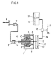
- the Clutch 1 via a generally provided on the handlebar of the motorcycle Hand lever 2 can be operated via a release device 3, the from a displaceable by a piston 4 on the pressure body 5 of the clutch 1 attacking control rod 6 exists.
- a pressure medium cylinder 7 which can be actuated via the hand lever 2, so that when pulling the hand lever 2, the pressure element 5 via the adjusting rod 6 against the closing force of the clutch springs 8 with a relief of Slats 9 and 10 is adjusted.
- you release the hand lever 2 the Pressure body 5 pressed over the clutch springs 8 against the plates 9 and 10 and the clutch 1 engaged.
- the pressure body 5 is also in the opposite direction via a control device 11 to the closing force of the clutch springs 8 depending on the engine load acted upon.
- a vacuum chamber 12 is provided, which over a membrane 13 or a piston is closed, the membrane 13 or the piston z. B. connected by the actuating rod 6 to the pressure body 5 is.
- This vacuum chamber 12 is on the intake pipe 14 of the engine connected so that the pressure body 5 in dependence on the negative pressure Intake pipe 14 is relieved.
- the vacuum in the vacuum chamber 12 via a control valve 15 depending on certain Operating parameters are controlled.
- the actuator 16 for the control valve 15 must be controlled accordingly via the control line 17 for this purpose become.
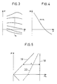
- the course of the engine torque M, which is dependent on the speed n, of an internal combustion engine at various negative pressures p in the intake manifold 14 is shown schematically in FIG. 3 in a characteristic field.
- the different torques M can be assigned certain negative pressures p.
- FIG. 4 This dependence is shown in which the negative pressure p in the intake pipe 14 has been plotted on the abscissa and the torque M for the rotational speed n 1 has been plotted on the ordinate.
- the characteristic curve obtained immediately shows that the negative pressure p in the intake pipe 14 of the engine can be used as a measure of the engine load, in particular if the respective engine speed n is additionally taken into account via the control valve 16.
- FIG. 5 shows a coordinate system on whose ordinate the torque M and on the abscissa the clutch torque M k can be read.
- the constant clutch torque caused by the clutch springs 8 is represented by the line 18.
- the slip limit 19 would be reached in each case if the effective clutch torque, taking into account the transmission ratios in the drive connection between the engine and clutch, corresponds to the effective engine torque M.
- the distance s between the lines 18 and 19 measured in the direction of the abscissa thus to a certain extent determines the safety against the clutch slipping. The greater the engine torque M, the smaller this security becomes.
- the interlocking slats 9 and 10 are in an inner basket 22 and an outer basket 23 held.
- This shaft 25 which is mounted in a housing 26, is driven by the countershaft connected to a manual transmission, the input gears designated 27 are.
- the actuating rod 6 for the pressure body 5 performed so that when the piston 4 is acted upon the release device 3 the pressure body 5 via a rotary bearing 28 in the usual way against the force of Clutch springs 8 can be lifted from the plates 9 and 10.
- the clutch 1 is on the clutch springs 8 indented again.
- this forms Coupling housing 29 on the front side is closed off by a membrane 13 Vacuum chamber 12, namely within a housing cover 30, the one Has connection 31 for a vacuum line 32 to the intake pipe 14, such as this is shown in FIG. 1. Since the membrane 13 with the pressure body 5 Is connected tensile via the rotary bearing 28, the pressure body 5 is counteracted the closing force of the clutch springs 8 depending on the engine load imposed what with a corresponding reduction in the slip limit is connected, as has already been explained in more detail.
Landscapes
- Engineering & Computer Science (AREA)
- General Engineering & Computer Science (AREA)
- Physics & Mathematics (AREA)
- Fluid Mechanics (AREA)
- Mechanical Engineering (AREA)
- Hydraulic Clutches, Magnetic Clutches, Fluid Clutches, And Fluid Joints (AREA)
- Mechanical Operated Clutches (AREA)
Description
- Fig. 1
- eine erfindungsgemäße Schaltkupplung für ein Motorrad in einem schematischen Blockschaltbild,
- Fig. 2
- eine erfindungsgemäße Schaltkupplung in einem Axialschnitt in einem größeren Maßstab,
- Fig. 3
- ein Diagramm, das den schematischen Drehmomentverlauf des Motors eines Motorrades über der Motordrehzahl in Abhängigkeit vom Unterdruck im Ansaugrohr veranschaulicht,
- Fig. 4
- ein Diagramm, in dem der Zusammenhäng zwischen dem Drehmoment und dem Ansaugdruck im Ansaugrohr bei einer bestimmten Drehzahl zu erkennen ist, und
- Fig. 5
- ein Diagramm, das die Beziehungen zwischen dem Drehmoment des Motors und dem Rutschmoment der Schaltkupplung wiederspiegelt.
Claims (6)
- Schaltkupplung (1) für ein Motorrad mit ineinandergreifenden, einem Innen- und einem Außenkorb (22 bzw. 23) zugeordneten Lamellen (9, 10) und mit einer Ausrückeinrichtung (3) für einen durch wenigstens eine Kupplungsfeder (8) belasteten Druckkörper (5) zur Kraftbeaufschlagung der Lamellen (9, 10), dadurch gekennzeichnet, daß der Druckkörper (5) über eine Steuereinrichtung (11) in Abhängigkeit von der Motorbelastung mit einer zur Schließkraft der Kupplungsfeder (8) gegensinnigen Kraft beaufschlagbar ist.
- Schaltkupplung nach Anspruch 1, dadurch gekennzeichnet, daß die Beaufschlagungskraft für den Druckkörper (5) zusätzlich in Abhängigkeit eines Betriebsparameters, beispielsweise in Abhängigkeit von der Stellung einer Getriebegangschaltung, der Drehzahl des getriebenen Hinterrades oder der Motordrehzahl, steuerbar ist.
- Schaltkupplung nach Anspruch 1 oder 2, dadurch gekennzeichnet, daß die Steuereinrichtung (11) aus einer an ein Ansaugrohr (14) des Motors angeschlossenen, über einen Kolben oder eine Membran (13) am Druckkörper (5) angreifenden Unterdruckkammer (12) besteht.
- Schaltkupplung nach den Ansprüchen 2 und 3, dadurch gekennzeichnet, daß zwischen dem Ansaugrohr (14) und der Unterdruckkammer (12) ein Steuerventil (15) vorgesehen ist.
- Schaltkupplung nach einem der Ansprüche 1 bis 4, dadurch gekennzeichnet, daß das Gehäuse (29) der Schaltkupplung (1) einen Unterdruckraum (12) bildet, der durch eine mit dem Druckkörper (5) über ein Drehlager verbundene Membran (13) abgeschlossen ist.
- Schaltkupplung nach Anspruch 5, dadurch gekennzeichnet, daß der Unterdruckraum (12) zwischen einem Gehäusedeckel (30) und der Membran (13) gebildet ist.
Applications Claiming Priority (3)
| Application Number | Priority Date | Filing Date | Title |
|---|---|---|---|
| AT2092/95 | 1995-12-22 | ||
| AT0209295A AT403507B (de) | 1995-12-22 | 1995-12-22 | Schaltkupplung für ein motorrad |
| AT209295 | 1995-12-22 |
Publications (3)
| Publication Number | Publication Date |
|---|---|
| EP0780591A2 EP0780591A2 (de) | 1997-06-25 |
| EP0780591A3 EP0780591A3 (de) | 1998-04-08 |
| EP0780591B1 true EP0780591B1 (de) | 2000-05-10 |
Family
ID=3527580
Family Applications (1)
| Application Number | Title | Priority Date | Filing Date |
|---|---|---|---|
| EP96890176A Expired - Lifetime EP0780591B1 (de) | 1995-12-22 | 1996-11-27 | Schaltkupplung für ein Motorrad |
Country Status (6)
| Country | Link |
|---|---|
| US (1) | US5860892A (de) |
| EP (1) | EP0780591B1 (de) |
| JP (1) | JPH09280272A (de) |
| AT (1) | AT403507B (de) |
| DE (1) | DE59605183D1 (de) |
| ES (1) | ES2146862T3 (de) |
Cited By (2)
| Publication number | Priority date | Publication date | Assignee | Title |
|---|---|---|---|---|
| CN105221597A (zh) * | 2015-09-28 | 2016-01-06 | 浙江新棉纺织有限公司 | 一种爪形离合器控制装置 |
| US9260153B2 (en) | 2005-07-14 | 2016-02-16 | Bayerische Motoren Werke Aktiengesellschaft | Vehicle in particular a motorcycle and engine/gearbox unit for a vehicle |
Families Citing this family (11)
| Publication number | Priority date | Publication date | Assignee | Title |
|---|---|---|---|---|
| US6165104A (en) | 1995-12-29 | 2000-12-26 | Robert Bosch Gmbh | System for controlling a clutch and/or a motor of a vehicle |
| US6409005B1 (en) * | 2000-08-03 | 2002-06-25 | Michael L. Heston | Clutch control system |
| DE10051374A1 (de) * | 2000-10-17 | 2002-04-18 | Zahnradfabrik Friedrichshafen | Kupplungsbetätigungseinrichtung |
| US7150348B2 (en) * | 2003-10-07 | 2006-12-19 | Magneti Marelli Powertrain Usa Llc | Ergonomic clutch actuator |
| EP1953405B1 (de) | 2007-02-05 | 2012-06-13 | Hoerbiger Antriebstechnik GmbH | Motorrad-Kupplung |
| JP2008232425A (ja) * | 2007-02-23 | 2008-10-02 | Yamaha Motor Co Ltd | 変速制御装置、鞍乗型車両、及び変速機の制御方法 |
| US20090107794A1 (en) | 2007-10-31 | 2009-04-30 | Brp-Rotax Gmbh & Co. Kg | Clutch actuation system |
| JP5132409B2 (ja) * | 2008-04-25 | 2013-01-30 | ヤマハ発動機株式会社 | 変速機構の制御装置、制御方法及び原動機付き車両の制御方法 |
| GB2476982A (en) * | 2010-01-19 | 2011-07-20 | Nissan Motor Mfg | Clutch having a controllable valve between input and output actuators |
| US8746429B1 (en) | 2012-01-12 | 2014-06-10 | Todd Patterson | Pneumatic lock-up clutch |
| US9206863B2 (en) | 2013-01-09 | 2015-12-08 | Mark Patterson | Clutch engagement mechanism |
Family Cites Families (10)
| Publication number | Priority date | Publication date | Assignee | Title |
|---|---|---|---|---|
| GB1543386A (en) * | 1975-05-12 | 1979-04-04 | Nissan Motor | Clutch control apparatus |
| JPS51147824A (en) * | 1975-06-13 | 1976-12-18 | Nissan Motor Co Ltd | Automatic clutch control system |
| DE3146738A1 (de) * | 1981-11-25 | 1983-06-01 | Emil Weber Fabrik für Ölhydraulik GmbH & Co, 7129 Güglingen | Vorrichtung zum automatischen ausruecken der kupplung eines kraftfahrzeugs |
| DE3373329D1 (en) * | 1982-07-02 | 1987-10-08 | Honda Motor Co Ltd | Friction clutch device |
| DE3445743A1 (de) * | 1984-12-14 | 1986-06-19 | Knorr-Bremse AG, 8000 München | Vorrichtung zum ausruecken einer einen motorischen antrieb mit einem kompressor verbindenden kupplung |
| IT1199954B (it) * | 1985-02-28 | 1989-01-05 | Stefano Venturini | Dispositivo di servofrizione per l'automatizzazione del funzionamento della frizione nei veicoli in genere |
| DE3737899A1 (de) * | 1987-11-07 | 1989-08-03 | Sachs Systemtechnik Gmbh | Vorrichtung zur automatischen betaetigung einer reibungskupplung |
| FR2645805B1 (fr) * | 1989-04-17 | 1995-07-13 | Luk Lamellen & Kupplungsbau | Procede de commande d'un embrayage a friction automatise agissant entre un moteur d'entrainement et une transmission, appareillage pour la mise en oeuvre du procede, et regulation associee d'un embrayage a friction |
| GB9101164D0 (en) * | 1991-01-18 | 1991-02-27 | Automotive Prod Plc | Clutch control system |
| US5469946A (en) * | 1994-02-01 | 1995-11-28 | Nguyen; Phuong H. | Clutch actuation system |
-
1995
- 1995-12-22 AT AT0209295A patent/AT403507B/de not_active IP Right Cessation
-
1996
- 1996-11-27 DE DE59605183T patent/DE59605183D1/de not_active Expired - Lifetime
- 1996-11-27 ES ES96890176T patent/ES2146862T3/es not_active Expired - Lifetime
- 1996-11-27 EP EP96890176A patent/EP0780591B1/de not_active Expired - Lifetime
- 1996-12-12 US US08/766,437 patent/US5860892A/en not_active Expired - Lifetime
- 1996-12-20 JP JP8342031A patent/JPH09280272A/ja active Pending
Cited By (3)
| Publication number | Priority date | Publication date | Assignee | Title |
|---|---|---|---|---|
| US9260153B2 (en) | 2005-07-14 | 2016-02-16 | Bayerische Motoren Werke Aktiengesellschaft | Vehicle in particular a motorcycle and engine/gearbox unit for a vehicle |
| CN105221597A (zh) * | 2015-09-28 | 2016-01-06 | 浙江新棉纺织有限公司 | 一种爪形离合器控制装置 |
| CN105221597B (zh) * | 2015-09-28 | 2017-10-31 | 安徽省创安体育用品有限公司 | 一种爪形离合器控制装置 |
Also Published As
| Publication number | Publication date |
|---|---|
| AT403507B (de) | 1998-03-25 |
| EP0780591A3 (de) | 1998-04-08 |
| DE59605183D1 (de) | 2000-06-15 |
| US5860892A (en) | 1999-01-19 |
| ATA209295A (de) | 1997-07-15 |
| JPH09280272A (ja) | 1997-10-28 |
| ES2146862T3 (es) | 2000-08-16 |
| EP0780591A2 (de) | 1997-06-25 |
Similar Documents
| Publication | Publication Date | Title |
|---|---|---|
| DE3042562C2 (de) | ||
| DE19637001A1 (de) | Kraftfahrzeug mit einer Einrichtung zur Betätigung des Drehmomentübertragungssystems und des Getriebes | |
| DE19721036A1 (de) | Fahrzeug mit einer Druckmittelanlage | |
| DE69601236T2 (de) | Steuerverfahren und -system für eine pneumatisch betätigte Kupplung | |
| AT403507B (de) | Schaltkupplung für ein motorrad | |
| DE2457928A1 (de) | Steuerung fuer hydraulikkupplung | |
| DE10201306A1 (de) | Kupplungsbetätigungssystem sowie darin verwendeter hydraulischer Mechanismus | |
| DE69207006T2 (de) | Verfahren zur steuerung einer automatischen kupplung und dazugehöriges automatisches getriebe | |
| DE68906116T2 (de) | Regelsystem fuer ein wahlweise zwei- oder vierradangetriebenes kraftfahrzeug mit einem stufenlos regelbaren umschlingungsgetriebe. | |
| DE3019274C2 (de) | ||
| EP0324928B1 (de) | Getriebesteuerung für ein stufenlos arbeitendes Getriebe | |
| EP0736708B1 (de) | Vorrichtung zum Verstellen des Fördervolumens einer Hydropumpe | |
| DE69017406T2 (de) | Hydraulische Steuerung für ein stufenloses Fahrzeuggetriebe mit zwei je nach Schalthebel Position aktivierbaren Schaltventilen. | |
| DE3504001C2 (de) | ||
| DE69403196T2 (de) | Getriebeeinheit, insbesondere für fahrzeuge und steuerverfahren dafür | |
| DE3914792C2 (de) | ||
| DE68902251T2 (de) | Einrichtung zur steuerung der uebertragungskupplung in einem fahrzeug mit vierradantrieb. | |
| DE60038351T2 (de) | Steuerung einer Startkupplung für ein stufenloses Getriebe | |
| EP0136544B1 (de) | Vorrichtung zum Reduzieren des Bremsmomentes von Brennkraftmaschinen in Kraftfahrzeugen | |
| DE3341160A1 (de) | Sperre-steuereinrichtung fuer einen drehmomentwandler in einem fahrzeug-automatikgetriebe | |
| EP0928374B1 (de) | Automatisch gesteuerte kupplung | |
| EP0470950B1 (de) | Vorrichtung zur elektro-hydraulischen betätigung einer ein verteilerdifferentialgetriebe eines kraftfahrzeugs sperrenden kupplung | |
| DE19730030A1 (de) | Betätigungseinrichtung | |
| DE3710080C1 (de) | Selbsttaetige Schaltvorrichtung eines Planetenraeder-Gangwechselgetriebes mit Mitteln zum Sperren des Einrueckens einer Rueckwaerts-Kupplung und/oder -Bremse | |
| DE2447531C2 (de) | Drosseldruckventil |
Legal Events
| Date | Code | Title | Description |
|---|---|---|---|
| PUAI | Public reference made under article 153(3) epc to a published international application that has entered the european phase |
Free format text: ORIGINAL CODE: 0009012 |
|
| AK | Designated contracting states |
Kind code of ref document: A2 Designated state(s): CH DE ES FR GB IT LI |
|
| PUAL | Search report despatched |
Free format text: ORIGINAL CODE: 0009013 |
|
| AK | Designated contracting states |
Kind code of ref document: A3 Designated state(s): CH DE ES FR GB IT LI |
|
| 17P | Request for examination filed |
Effective date: 19980928 |
|
| 17Q | First examination report despatched |
Effective date: 19981204 |
|
| GRAG | Despatch of communication of intention to grant |
Free format text: ORIGINAL CODE: EPIDOS AGRA |
|
| GRAG | Despatch of communication of intention to grant |
Free format text: ORIGINAL CODE: EPIDOS AGRA |
|
| GRAH | Despatch of communication of intention to grant a patent |
Free format text: ORIGINAL CODE: EPIDOS IGRA |
|
| GRAH | Despatch of communication of intention to grant a patent |
Free format text: ORIGINAL CODE: EPIDOS IGRA |
|
| GRAA | (expected) grant |
Free format text: ORIGINAL CODE: 0009210 |
|
| AK | Designated contracting states |
Kind code of ref document: B1 Designated state(s): CH DE ES FR GB IT LI |
|
| REG | Reference to a national code |
Ref country code: CH Ref legal event code: EP |
|
| REF | Corresponds to: |
Ref document number: 59605183 Country of ref document: DE Date of ref document: 20000615 |
|
| GBT | Gb: translation of ep patent filed (gb section 77(6)(a)/1977) |
Effective date: 20000602 |
|
| REG | Reference to a national code |
Ref country code: CH Ref legal event code: NV Representative=s name: DIPL.-ING. W. STEUDTNER |
|
| ET | Fr: translation filed | ||
| ITF | It: translation for a ep patent filed | ||
| REG | Reference to a national code |
Ref country code: ES Ref legal event code: FG2A Ref document number: 2146862 Country of ref document: ES Kind code of ref document: T3 |
|
| PLBE | No opposition filed within time limit |
Free format text: ORIGINAL CODE: 0009261 |
|
| STAA | Information on the status of an ep patent application or granted ep patent |
Free format text: STATUS: NO OPPOSITION FILED WITHIN TIME LIMIT |
|
| 26N | No opposition filed | ||
| PGFP | Annual fee paid to national office [announced via postgrant information from national office to epo] |
Ref country code: ES Payment date: 20011119 Year of fee payment: 6 |
|
| PGFP | Annual fee paid to national office [announced via postgrant information from national office to epo] |
Ref country code: FR Payment date: 20011127 Year of fee payment: 6 |
|
| PGFP | Annual fee paid to national office [announced via postgrant information from national office to epo] |
Ref country code: CH Payment date: 20011130 Year of fee payment: 6 |
|
| REG | Reference to a national code |
Ref country code: GB Ref legal event code: IF02 |
|
| PG25 | Lapsed in a contracting state [announced via postgrant information from national office to epo] |
Ref country code: ES Free format text: LAPSE BECAUSE OF NON-PAYMENT OF DUE FEES Effective date: 20021128 |
|
| PG25 | Lapsed in a contracting state [announced via postgrant information from national office to epo] |
Ref country code: LI Free format text: LAPSE BECAUSE OF NON-PAYMENT OF DUE FEES Effective date: 20021130 Ref country code: CH Free format text: LAPSE BECAUSE OF NON-PAYMENT OF DUE FEES Effective date: 20021130 |
|
| REG | Reference to a national code |
Ref country code: CH Ref legal event code: PL |
|
| PG25 | Lapsed in a contracting state [announced via postgrant information from national office to epo] |
Ref country code: FR Free format text: LAPSE BECAUSE OF NON-PAYMENT OF DUE FEES Effective date: 20030731 |
|
| REG | Reference to a national code |
Ref country code: FR Ref legal event code: ST |
|
| REG | Reference to a national code |
Ref country code: ES Ref legal event code: FD2A Effective date: 20031213 |
|
| REG | Reference to a national code |
Ref country code: DE Ref legal event code: R082 Ref document number: 59605183 Country of ref document: DE Representative=s name: PATENTANWAELTE BERNHARDT/WOLFF PARTNERSCHAFT, DE |
|
| PGFP | Annual fee paid to national office [announced via postgrant information from national office to epo] |
Ref country code: DE Payment date: 20151022 Year of fee payment: 20 Ref country code: GB Payment date: 20151027 Year of fee payment: 20 Ref country code: IT Payment date: 20151023 Year of fee payment: 20 |
|
| REG | Reference to a national code |
Ref country code: DE Ref legal event code: R071 Ref document number: 59605183 Country of ref document: DE |
|
| REG | Reference to a national code |
Ref country code: GB Ref legal event code: PE20 Expiry date: 20161126 |
|
| PG25 | Lapsed in a contracting state [announced via postgrant information from national office to epo] |
Ref country code: GB Free format text: LAPSE BECAUSE OF EXPIRATION OF PROTECTION Effective date: 20161126 |