EP0780552B1 - Pot d'échappement de véhicule automobile - Google Patents
Pot d'échappement de véhicule automobile Download PDFInfo
- Publication number
- EP0780552B1 EP0780552B1 EP96402533A EP96402533A EP0780552B1 EP 0780552 B1 EP0780552 B1 EP 0780552B1 EP 96402533 A EP96402533 A EP 96402533A EP 96402533 A EP96402533 A EP 96402533A EP 0780552 B1 EP0780552 B1 EP 0780552B1
- Authority
- EP
- European Patent Office
- Prior art keywords
- steel
- central part
- compris entre
- degrees celsius
- exhaust
- Prior art date
- Legal status (The legal status is an assumption and is not a legal conclusion. Google has not performed a legal analysis and makes no representation as to the accuracy of the status listed.)
- Expired - Lifetime
Links
Images
Classifications
-
- F—MECHANICAL ENGINEERING; LIGHTING; HEATING; WEAPONS; BLASTING
- F01—MACHINES OR ENGINES IN GENERAL; ENGINE PLANTS IN GENERAL; STEAM ENGINES
- F01N—GAS-FLOW SILENCERS OR EXHAUST APPARATUS FOR MACHINES OR ENGINES IN GENERAL; GAS-FLOW SILENCERS OR EXHAUST APPARATUS FOR INTERNAL-COMBUSTION ENGINES
- F01N1/00—Silencing apparatus characterised by method of silencing
-
- F—MECHANICAL ENGINEERING; LIGHTING; HEATING; WEAPONS; BLASTING
- F01—MACHINES OR ENGINES IN GENERAL; ENGINE PLANTS IN GENERAL; STEAM ENGINES
- F01N—GAS-FLOW SILENCERS OR EXHAUST APPARATUS FOR MACHINES OR ENGINES IN GENERAL; GAS-FLOW SILENCERS OR EXHAUST APPARATUS FOR INTERNAL-COMBUSTION ENGINES
- F01N13/00—Exhaust or silencing apparatus characterised by constructional features
- F01N13/16—Selection of particular materials
-
- C—CHEMISTRY; METALLURGY
- C21—METALLURGY OF IRON
- C21D—MODIFYING THE PHYSICAL STRUCTURE OF FERROUS METALS; GENERAL DEVICES FOR HEAT TREATMENT OF FERROUS OR NON-FERROUS METALS OR ALLOYS; MAKING METAL MALLEABLE, e.g. BY DECARBURISATION OR TEMPERING
- C21D8/00—Modifying the physical properties of ferrous metals or ferrous alloys by deformation combined with, or followed by, heat treatment
- C21D8/02—Modifying the physical properties of ferrous metals or ferrous alloys by deformation combined with, or followed by, heat treatment during manufacturing of plates or strips
- C21D8/0221—Modifying the physical properties of ferrous metals or ferrous alloys by deformation combined with, or followed by, heat treatment during manufacturing of plates or strips characterised by the working steps
- C21D8/0226—Hot rolling
-
- C—CHEMISTRY; METALLURGY
- C22—METALLURGY; FERROUS OR NON-FERROUS ALLOYS; TREATMENT OF ALLOYS OR NON-FERROUS METALS
- C22C—ALLOYS
- C22C38/00—Ferrous alloys, e.g. steel alloys
-
- F—MECHANICAL ENGINEERING; LIGHTING; HEATING; WEAPONS; BLASTING
- F01—MACHINES OR ENGINES IN GENERAL; ENGINE PLANTS IN GENERAL; STEAM ENGINES
- F01N—GAS-FLOW SILENCERS OR EXHAUST APPARATUS FOR MACHINES OR ENGINES IN GENERAL; GAS-FLOW SILENCERS OR EXHAUST APPARATUS FOR INTERNAL-COMBUSTION ENGINES
- F01N2510/00—Surface coverings
- F01N2510/08—Surface coverings for corrosion prevention
Definitions
- the present invention relates to an exhaust pipe motor vehicle.
- a motor vehicle exhaust pipe is made up an outer shell, an inner shell and a central part made up of perforated pipes and assembled transverse partitions between them to form a chicane, called tripaille.
- the central part of the exhaust pipes, as well as their inner shell must withstand very acidic and very basics of condensates that form during use when expansion therein of the burnt gases from the vehicle combustion engine automobile.
- European Patent No. 007,131 describes such a particular type of enamel, the manufacturing and implementation of which complex and therefore entail an additional cost compared to the use of standard enamels.
- the present invention provides an exhaust for motor vehicle, resistant to severe attack by condensates which are formed in its central part, and which is of a low cost.
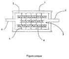
- an exhaust pipe motor vehicle consists of an outer casing 1, a inner casing 2 and a central part 3.
- the central part 3 consists of perforated tubing 4 and transverse partitions 5 assembled together to form a baffle allowing the expansion of the burnt gases of the combustion engine of the motor vehicle.
- Exhaust also includes tubing inlet 6, connecting it to the engine exhaust manifold and a outlet pipe 7 allowing gases to be evacuated to the atmosphere exhaust relaxed and rid of a certain amount of harmful particles.
- the steel is obtained by hot rolling at a final rolling temperature exceeding the point Ar 3 to obtain a strip, which is coiled at a temperature above 600 degrees Celsius, and after cold rolling, is subjected to recrystallization annealing.
- recrystallization annealing which can be indifferently a base bell annealing or a continuous annealing.
- the strip winding temperature is greater than 700 degrees Celsius.
- the steel is obtained by hot rolling at a final rolling temperature exceeding the point Ar 3 to obtain a strip, which is coiled at a temperature above 700 degrees Celsius, and after cold rolling, is subjected to recrystallization annealing. .
- the strip winding temperature is greater than 750 degrees Celsius.
- Annealing is a base decarburizing annealing in an expanded coil, that is to say a bell annealing of the coil wound in turns contiguous.
- the non-contiguous turn coil is heated in a bell under HNx atmosphere up to about 600 degrees Celsius, then continue the annealing by subjecting it to a current of water vapour.
- the steel is obtained by hot rolling at a final rolling temperature exceeding the point Ar 3 to obtain a strip, which is coiled at a temperature above 600 degrees Celsius, and after cold rolling, is subjected to recrystallization annealing. , basic annealing or continuous annealing.
- the strip is wound at a temperature greater than 700 degrees Celsius.
- the central part 3 can be made of an enameled steel exhaust pipe, perfectly resistant to corrosion, easy to use, using a standard type of enamel, while avoiding the defects linked to the annealing of enamel and defects of the "nail stroke defect" type, and which is low cost.
- the inner casing 2 of the exhaust pipe can be made either of stainless steel or aluminized steel, as well as the outer casing 1.
- the best compromise between efficiency, i.e. essentially corrosion resistance, and cost, consists in making either an exhaust pipe whose central part 3 and the inner envelope 2 are made of enamelled steel, the outer casing 1 being made of aluminized steel, ie an exhaust pipe whose central part 3 is in enamelled steel, the inner envelope 2 is in stainless steel and the outer casing 1 is made of aluminized steel.
- Two exhaust pipes were produced with an envelope inner 2 in stainless steel, outer casing 1 in steel aluminized and a central part 3 in enamelled steel.
- the steel was obtained by hot rolling at a temperature final rolling equal to 890 degrees Celsius to obtain a strip, which was wound at a temperature of 760 degrees Celsius, and after cold rolling, was subjected to recrystallization annealing in coil expanded.
- This central part 3 was enameled by immersing it in a bath of enamel of common mass resistant to heat and corrosion, having the following composition in weight percent: S i O 2 54 Z r O 2 2 P 2 O 5 1 B 2 O 3 14 Al 2 O 3 3 C a O 4 B a O 5 Na 2 O 11 K 2 O 2 Li 2 O 2 N i O 1 C o O 0.5 C u O 0.5.
- the steel was obtained by hot rolling at a temperature final rolling equal to 890 degrees Celsius to obtain a strip, which was wound at a temperature of 710 degrees Celsius, and after cold rolling, was subjected to continuous recrystallization annealing.
- This central part 3 has been enamelled by immersing it in a bath of the same enamel as before.
- the use of enamelled steels to make at least the central part of a pot exhaust said steel having a composition according to the invention, allows guarantee good resistance of the enamelled steel to the thermal shocks it undergoes in operation, that is to say that the cracking of the enamel is avoided.
- steel containing in thousandths of a percent weight between 0 and 10 carbon and between 50 and 150 titanium has a better resistance to thermal shock than steel containing in thousandths of per hundred weight between 0 and 4 of carbon and between 0 and 10 of titanium, which still has very good resistance to thermal shock, better than standard mild steels.
Landscapes
- Engineering & Computer Science (AREA)
- Chemical & Material Sciences (AREA)
- Mechanical Engineering (AREA)
- Materials Engineering (AREA)
- Organic Chemistry (AREA)
- Metallurgy (AREA)
- General Engineering & Computer Science (AREA)
- Combustion & Propulsion (AREA)
- Crystallography & Structural Chemistry (AREA)
- Thermal Sciences (AREA)
- Physics & Mathematics (AREA)
- Exhaust Silencers (AREA)
- Heat Treatment Of Sheet Steel (AREA)
- Control Of Throttle Valves Provided In The Intake System Or In The Exhaust System (AREA)
- Heat Treatment Of Steel (AREA)
- Valve Device For Special Equipments (AREA)
- Exhaust-Gas Circulating Devices (AREA)
Description
- carbone compris entre 0 et 10
- manganèse compris entre 150 et 400
- phosphore compris entre 0 et 20
- soufre compris entre 10 et 30
- aluminium compris entre 10 et 50
- titane compris entre 50 et 150
- cuivre compris entre 10 et 60
- azote compris entre 5 et 15,
- le feuillard est bobiné à une température supérieure à 700 degrés Celsius.
- carbone compris entre 0 et 100
- manganèse compris entre 0 et 500
- phosphore compris entre 0 et 30
- soufre compris entre 0 et 40
- aluminium compris entre 0 et 60
- titane compris entre 0 et 200
- cuivre compris entre 0 et 60
- azote compris entre 0 et 15,
- carbone compris entre 0 et 4
- manganèse compris entre 150 et 400
- phosphore compris entre 10 et 15
- soufre compris entre 15 et 40
- aluminium compris entre 10 et 50
- titane compris entre 0 et 10
- cuivre compris entre 20 et 30
- azote compris entre 1,5 et 7,5,
- carbone compris entre 0 et 10
- manganèse compris entre 150 et 400
- phosphore compris entre 0 et 20
- soufre compris entre 10 et 30
- aluminium compris entre 10 et 50
- titane compris entre 50 et 150
- cuivre compris entre 10 et 60
- azote compris entre 5 et 15,
- carbone égal à 2
- manganèse égal à 270
- phosphore égal à 12
- soufre égal à 22
- aluminium égal à 18
- titane égal à 1
- cuivre égal à 22
- azote égal à 4,
| SiO2 | 54 |
| ZrO2 | 2 |
| P2O5 | 1 |
| B2O3 | 14 |
| Al2O3 | 3 |
| CaO | 4 |
| BaO | 5 |
| Na2O | 11 |
| K2O | 2 |
| Li2O | 2 |
| NiO | 1 |
| CoO | 0,5 |
| CuO | 0,5. |
- carbone égal à 2
- manganèse égal à 200
- phosphore égal à 15
- soufre égal à 20
- aluminium égal à 30
- titane égal à 100
- cuivre égal à 40
- azote égal à 9,
Claims (2)
- Pot d'échappement de véhicule automobile, constitué d'une enveloppe extérieure (1), une enveloppe intérieure (2) et une partie centrale (3) constituée de tubulures perforées (4) et de cloisons transversales (5) assemblées entre elles pour former chicanes, caractérisé en ce que l'enveloppe intérieure (2) et ou la partie centrale (3) est réalisée en un acier émaillé, l'acier ayant la composition suivante en millièmes de pour-cent poids :le reste étant du fer et des impuretés résiduelles,carbone compris entre 0 et 10manganèse compris entre 150 et 400phosphore compris entre 0 et 20soufre compris entre 10 et 30aluminium compris entre 10 et 50titane compris entre 50 et 150cuivre compris entre 10 et 60azote compris entre 5 et 15,
ledit acier étant obtenu par laminage à chaud à une température finale de laminage dépassant le point Ar3 pour obtenir un feuillard, lequel est bobiné à une température supérieure à 600 degrés Celsius, et après laminage à froid, est soumis à un recuit de recristallisation. - Pot d'échappement de véhicule automobile selon la revendication 1, caractérisé en ce que le feuillard est bobiné à une température supérieure à 700 degrés Celsius.
Applications Claiming Priority (2)
| Application Number | Priority Date | Filing Date | Title |
|---|---|---|---|
| FR9515087 | 1995-12-20 | ||
| FR9515087A FR2742802B1 (fr) | 1995-12-20 | 1995-12-20 | Pot d'echappement de vehicule automobile |
Publications (2)
| Publication Number | Publication Date |
|---|---|
| EP0780552A1 EP0780552A1 (fr) | 1997-06-25 |
| EP0780552B1 true EP0780552B1 (fr) | 2001-09-12 |
Family
ID=9485673
Family Applications (1)
| Application Number | Title | Priority Date | Filing Date |
|---|---|---|---|
| EP96402533A Expired - Lifetime EP0780552B1 (fr) | 1995-12-20 | 1996-11-26 | Pot d'échappement de véhicule automobile |
Country Status (10)
| Country | Link |
|---|---|
| US (1) | US5739485A (fr) |
| EP (1) | EP0780552B1 (fr) |
| JP (1) | JPH09189223A (fr) |
| KR (1) | KR970044261A (fr) |
| AT (1) | ATE205580T1 (fr) |
| DE (1) | DE69615137T2 (fr) |
| DK (1) | DK0780552T3 (fr) |
| ES (1) | ES2161997T3 (fr) |
| FR (1) | FR2742802B1 (fr) |
| PT (1) | PT780552E (fr) |
Families Citing this family (5)
| Publication number | Priority date | Publication date | Assignee | Title |
|---|---|---|---|---|
| US6571910B2 (en) | 2000-12-20 | 2003-06-03 | Quiet Storm, Llc | Method and apparatus for improved noise attenuation in a dissipative internal combustion engine exhaust muffler |
| ES2247383T3 (es) * | 2001-10-29 | 2006-03-01 | Nippon Steel Corporation | Lamina de acero para el esmaltado vitreo excelente en sus posibilidades de ser trabajada y de resistencia a la formacion de escamas, y metodo para producir la misma. |
| US6837235B2 (en) * | 2002-03-14 | 2005-01-04 | Ssw Holdings Company, Inc. | Porcelain oven rack |
| US20070272231A1 (en) * | 2006-05-25 | 2007-11-29 | Ssw Holding Company, Inc. | Oven rack having an integral lubricious, dry porcelain surface |
| CN108251752B (zh) * | 2018-01-18 | 2019-11-22 | 唐山钢铁集团有限责任公司 | 一种机动车消音片基板及其生产方法 |
Family Cites Families (10)
| Publication number | Priority date | Publication date | Assignee | Title |
|---|---|---|---|---|
| AU2433671A (en) * | 1970-02-06 | 1972-07-20 | Armco Steel Corporation | Product and method for making drawing quality enameling stock |
| US4141724A (en) * | 1978-06-21 | 1979-02-27 | United States Steel Corporation | Low-cost, high temperature oxidation-resistant steel |
| DE2962334D1 (en) * | 1978-07-07 | 1982-04-29 | Reimbold & Strick | Enamelled sound absorber and method for its enamelling |
| US4254684A (en) * | 1979-01-25 | 1981-03-10 | Helpinstill Iii Charles T | Breakdown piano |
| DE2917586C2 (de) * | 1979-04-30 | 1982-11-18 | Werner Dr.-Ing. 8450 Amberg Baumann | Auspufftopf aus emailliertem Stahlblech |
| US4264684A (en) * | 1979-12-17 | 1981-04-28 | Bethlehem Steel Corporation | Zinc-alloy coated ferrous product resistant to embrittlement |
| JPH01275736A (ja) * | 1988-04-28 | 1989-11-06 | Nippon Steel Corp | 加工性に優れた連続鋳造製ほうろう用鋼板およびその製造法 |
| CA2036374A1 (fr) * | 1989-07-19 | 1991-01-20 | Kazunori Osawa | Methode de production de toles d'acier a emailler a adherence amelioree |
| JPH04154919A (ja) * | 1990-10-15 | 1992-05-27 | Sumitomo Metal Ind Ltd | 加工性に優れたほうろう用冷延鋼板の製造法 |
| DE9318921U1 (de) * | 1993-12-09 | 1994-02-03 | Audi Ag, 85057 Ingolstadt | Auspuffanlage für eine Diesel-Brennkraftmaschine |
-
1995
- 1995-12-20 FR FR9515087A patent/FR2742802B1/fr not_active Expired - Fee Related
-
1996
- 1996-11-26 DK DK96402533T patent/DK0780552T3/da active
- 1996-11-26 DE DE69615137T patent/DE69615137T2/de not_active Expired - Fee Related
- 1996-11-26 PT PT96402533T patent/PT780552E/pt unknown
- 1996-11-26 AT AT96402533T patent/ATE205580T1/de not_active IP Right Cessation
- 1996-11-26 EP EP96402533A patent/EP0780552B1/fr not_active Expired - Lifetime
- 1996-11-26 ES ES96402533T patent/ES2161997T3/es not_active Expired - Lifetime
- 1996-12-20 JP JP8355278A patent/JPH09189223A/ja not_active Withdrawn
- 1996-12-20 KR KR1019960069233A patent/KR970044261A/ko not_active Abandoned
- 1996-12-20 US US08/772,272 patent/US5739485A/en not_active Expired - Fee Related
Also Published As
| Publication number | Publication date |
|---|---|
| JPH09189223A (ja) | 1997-07-22 |
| FR2742802A1 (fr) | 1997-06-27 |
| PT780552E (pt) | 2002-02-28 |
| KR970044261A (ko) | 1997-07-26 |
| DE69615137T2 (de) | 2002-06-20 |
| EP0780552A1 (fr) | 1997-06-25 |
| ATE205580T1 (de) | 2001-09-15 |
| FR2742802B1 (fr) | 1998-01-30 |
| US5739485A (en) | 1998-04-14 |
| ES2161997T3 (es) | 2001-12-16 |
| DE69615137D1 (de) | 2001-10-18 |
| DK0780552T3 (da) | 2001-12-31 |
Similar Documents
| Publication | Publication Date | Title |
|---|---|---|
| EP1999287B1 (fr) | Procede de recuit et de preparation en continu d'une bande d'acier a haute resistance en vue de sa galvanisation au trempe | |
| EP0835947B1 (fr) | Tole aluminiée à faible émissivité et procédé pour obtenir ledit produit | |
| FR2835533A1 (fr) | TOLE EN ALLIAGE Al-Si-Mg POUR PEAU DE CARROSSERIE AUTOMOBILE | |
| EP0780552B1 (fr) | Pot d'échappement de véhicule automobile | |
| FR2472022A1 (fr) | Procede de production d'une tole d'acier laminee a deux phases dont une est formee par refroidissement rapide apres recuit continu | |
| JP2008523243A (ja) | 高張力鋼ストリップを溶融浸漬コーティングする方法 | |
| EP3972462B1 (fr) | Article culinaire comportant une calotte en aluminium | |
| RU2341581C2 (ru) | Железо-хром-алюминиевый сплав | |
| FR2480311A1 (fr) | Tole d'acier laminee a froid a faible limite d'allongement et haute resistance apte a un emboutissage profond | |
| FR2773819A1 (fr) | Alliage d'aluminium pour boitier d'aerosol | |
| FR2707669A1 (fr) | Procédé de fabrication d'une feuille mince apte à la confection d'éléments constitutifs de boîtes. | |
| FR2694575A1 (fr) | Procédé pour le traitement de revêtements en MCrAlZ. | |
| FR2775297A1 (fr) | Tole dotee d'un revetement d'aluminium resistant a la fissuration | |
| CN100561078C (zh) | 铝包铜毛细管的生产工艺 | |
| CH636379A5 (fr) | Alliage d'aluminium et ses applications. | |
| FI4437155T3 (fi) | Sinkkipinnoitettu Mn:ää sisältävä kehittynyt erityisluja teräs ja sen valmistusmenetelmä | |
| BE1008566A6 (fr) | Substrat aluminie, son utilisation et methode pour le fabriquer. | |
| JP5589262B2 (ja) | 断熱鋼板及び金属製真空二重容器 | |
| FR2622632A1 (fr) | Pot d'echappement catalytique pour gaz brules de moteurs thermiques | |
| FR3096248A1 (fr) | Article culinaire comportant une paroi laterale amincie | |
| JP6075707B2 (ja) | 電極材料、点火プラグ用電極、及び点火プラグ | |
| FR2471415A1 (fr) | Procede de recuit final pour une tole ou bande d'acier a grains orientes pour applications electriques | |
| JPS5935667A (ja) | 鋼管の表面処理方法 | |
| FR2930023A1 (fr) | Procede de traitement de surface d'un echangeur de chaleur resistant a la corrosion | |
| JPS59103919A (ja) | 車両用排気系部品の製造方法 |
Legal Events
| Date | Code | Title | Description |
|---|---|---|---|
| PUAI | Public reference made under article 153(3) epc to a published international application that has entered the european phase |
Free format text: ORIGINAL CODE: 0009012 |
|
| AK | Designated contracting states |
Kind code of ref document: A1 Designated state(s): AT BE CH DE DK ES FI FR GB GR IE IT LI LU NL PT SE |
|
| 17P | Request for examination filed |
Effective date: 19970707 |
|
| 17Q | First examination report despatched |
Effective date: 19991227 |
|
| GRAG | Despatch of communication of intention to grant |
Free format text: ORIGINAL CODE: EPIDOS AGRA |
|
| GRAG | Despatch of communication of intention to grant |
Free format text: ORIGINAL CODE: EPIDOS AGRA |
|
| GRAG | Despatch of communication of intention to grant |
Free format text: ORIGINAL CODE: EPIDOS AGRA |
|
| GRAH | Despatch of communication of intention to grant a patent |
Free format text: ORIGINAL CODE: EPIDOS IGRA |
|
| GRAH | Despatch of communication of intention to grant a patent |
Free format text: ORIGINAL CODE: EPIDOS IGRA |
|
| GRAA | (expected) grant |
Free format text: ORIGINAL CODE: 0009210 |
|
| AK | Designated contracting states |
Kind code of ref document: B1 Designated state(s): AT BE CH DE DK ES FI FR GB GR IE IT LI LU NL PT SE |
|
| REF | Corresponds to: |
Ref document number: 205580 Country of ref document: AT Date of ref document: 20010915 Kind code of ref document: T |
|
| REG | Reference to a national code |
Ref country code: CH Ref legal event code: EP |
|
| REG | Reference to a national code |
Ref country code: IE Ref legal event code: FG4D Free format text: FRENCH |
|
| REF | Corresponds to: |
Ref document number: 69615137 Country of ref document: DE Date of ref document: 20011018 |
|
| REG | Reference to a national code |
Ref country code: ES Ref legal event code: FG2A Ref document number: 2161997 Country of ref document: ES Kind code of ref document: T3 |
|
| REG | Reference to a national code |
Ref country code: DK Ref legal event code: T3 |
|
| REG | Reference to a national code |
Ref country code: GB Ref legal event code: IF02 |
|
| GBT | Gb: translation of ep patent filed (gb section 77(6)(a)/1977) |
Effective date: 20011214 |
|
| REG | Reference to a national code |
Ref country code: PT Ref legal event code: SC4A Free format text: AVAILABILITY OF NATIONAL TRANSLATION Effective date: 20011108 Ref country code: GR Ref legal event code: EP Ref document number: 20010402046 Country of ref document: GR |
|
| PLBE | No opposition filed within time limit |
Free format text: ORIGINAL CODE: 0009261 |
|
| STAA | Information on the status of an ep patent application or granted ep patent |
Free format text: STATUS: NO OPPOSITION FILED WITHIN TIME LIMIT |
|
| 26N | No opposition filed | ||
| PGFP | Annual fee paid to national office [announced via postgrant information from national office to epo] |
Ref country code: CH Payment date: 20021017 Year of fee payment: 7 |
|
| PGFP | Annual fee paid to national office [announced via postgrant information from national office to epo] |
Ref country code: PT Payment date: 20021021 Year of fee payment: 7 |
|
| PGFP | Annual fee paid to national office [announced via postgrant information from national office to epo] |
Ref country code: IE Payment date: 20021023 Year of fee payment: 7 |
|
| PGFP | Annual fee paid to national office [announced via postgrant information from national office to epo] |
Ref country code: GR Payment date: 20021024 Year of fee payment: 7 |
|
| PGFP | Annual fee paid to national office [announced via postgrant information from national office to epo] |
Ref country code: SE Payment date: 20021028 Year of fee payment: 7 Ref country code: DK Payment date: 20021028 Year of fee payment: 7 |
|
| PGFP | Annual fee paid to national office [announced via postgrant information from national office to epo] |
Ref country code: AT Payment date: 20021029 Year of fee payment: 7 |
|
| PGFP | Annual fee paid to national office [announced via postgrant information from national office to epo] |
Ref country code: GB Payment date: 20021030 Year of fee payment: 7 Ref country code: FI Payment date: 20021030 Year of fee payment: 7 |
|
| PGFP | Annual fee paid to national office [announced via postgrant information from national office to epo] |
Ref country code: FR Payment date: 20021104 Year of fee payment: 7 |
|
| PGFP | Annual fee paid to national office [announced via postgrant information from national office to epo] |
Ref country code: LU Payment date: 20021105 Year of fee payment: 7 |
|
| PGFP | Annual fee paid to national office [announced via postgrant information from national office to epo] |
Ref country code: DE Payment date: 20021111 Year of fee payment: 7 |
|
| PGFP | Annual fee paid to national office [announced via postgrant information from national office to epo] |
Ref country code: NL Payment date: 20021114 Year of fee payment: 7 |
|
| PGFP | Annual fee paid to national office [announced via postgrant information from national office to epo] |
Ref country code: ES Payment date: 20021118 Year of fee payment: 7 |
|
| PGFP | Annual fee paid to national office [announced via postgrant information from national office to epo] |
Ref country code: BE Payment date: 20021122 Year of fee payment: 7 |
|
| PG25 | Lapsed in a contracting state [announced via postgrant information from national office to epo] |
Ref country code: LU Free format text: LAPSE BECAUSE OF NON-PAYMENT OF DUE FEES Effective date: 20031126 Ref country code: IE Free format text: LAPSE BECAUSE OF NON-PAYMENT OF DUE FEES Effective date: 20031126 Ref country code: GB Free format text: LAPSE BECAUSE OF NON-PAYMENT OF DUE FEES Effective date: 20031126 Ref country code: FI Free format text: LAPSE BECAUSE OF NON-PAYMENT OF DUE FEES Effective date: 20031126 Ref country code: AT Free format text: LAPSE BECAUSE OF NON-PAYMENT OF DUE FEES Effective date: 20031126 |
|
| PG25 | Lapsed in a contracting state [announced via postgrant information from national office to epo] |
Ref country code: SE Free format text: LAPSE BECAUSE OF NON-PAYMENT OF DUE FEES Effective date: 20031127 Ref country code: ES Free format text: LAPSE BECAUSE OF NON-PAYMENT OF DUE FEES Effective date: 20031127 |
|
| PG25 | Lapsed in a contracting state [announced via postgrant information from national office to epo] |
Ref country code: LI Free format text: LAPSE BECAUSE OF NON-PAYMENT OF DUE FEES Effective date: 20031130 Ref country code: CH Free format text: LAPSE BECAUSE OF NON-PAYMENT OF DUE FEES Effective date: 20031130 Ref country code: BE Free format text: LAPSE BECAUSE OF NON-PAYMENT OF DUE FEES Effective date: 20031130 |
|
| PG25 | Lapsed in a contracting state [announced via postgrant information from national office to epo] |
Ref country code: DK Free format text: LAPSE BECAUSE OF NON-PAYMENT OF DUE FEES Effective date: 20031201 |
|
| BERE | Be: lapsed |
Owner name: S.A. *SOLLAC Effective date: 20031130 |
|
| PG25 | Lapsed in a contracting state [announced via postgrant information from national office to epo] |
Ref country code: PT Free format text: LAPSE BECAUSE OF NON-PAYMENT OF DUE FEES Effective date: 20040531 |
|
| PG25 | Lapsed in a contracting state [announced via postgrant information from national office to epo] |
Ref country code: NL Free format text: LAPSE BECAUSE OF NON-PAYMENT OF DUE FEES Effective date: 20040601 |
|
| PG25 | Lapsed in a contracting state [announced via postgrant information from national office to epo] |
Ref country code: DE Free format text: LAPSE BECAUSE OF NON-PAYMENT OF DUE FEES Effective date: 20040602 |
|
| PG25 | Lapsed in a contracting state [announced via postgrant information from national office to epo] |
Ref country code: GR Free format text: LAPSE BECAUSE OF NON-PAYMENT OF DUE FEES Effective date: 20040603 |
|
| EUG | Se: european patent has lapsed | ||
| REG | Reference to a national code |
Ref country code: DK Ref legal event code: EBP |
|
| GBPC | Gb: european patent ceased through non-payment of renewal fee |
Effective date: 20031126 |
|
| REG | Reference to a national code |
Ref country code: CH Ref legal event code: PL |
|
| PG25 | Lapsed in a contracting state [announced via postgrant information from national office to epo] |
Ref country code: FR Free format text: LAPSE BECAUSE OF NON-PAYMENT OF DUE FEES Effective date: 20040730 |
|
| NLV4 | Nl: lapsed or anulled due to non-payment of the annual fee |
Effective date: 20040601 |
|
| REG | Reference to a national code |
Ref country code: IE Ref legal event code: MM4A |
|
| REG | Reference to a national code |
Ref country code: PT Ref legal event code: MM4A Free format text: LAPSE DUE TO NON-PAYMENT OF FEES Effective date: 20040531 |
|
| REG | Reference to a national code |
Ref country code: FR Ref legal event code: ST |
|
| REG | Reference to a national code |
Ref country code: ES Ref legal event code: FD2A Effective date: 20031127 |
|
| PG25 | Lapsed in a contracting state [announced via postgrant information from national office to epo] |
Ref country code: IT Free format text: LAPSE BECAUSE OF NON-PAYMENT OF DUE FEES;WARNING: LAPSES OF ITALIAN PATENTS WITH EFFECTIVE DATE BEFORE 2007 MAY HAVE OCCURRED AT ANY TIME BEFORE 2007. THE CORRECT EFFECTIVE DATE MAY BE DIFFERENT FROM THE ONE RECORDED. Effective date: 20051126 |