EP0779224B1 - Verpackung für Teile eines Microwellenofens - Google Patents
Verpackung für Teile eines Microwellenofens Download PDFInfo
- Publication number
- EP0779224B1 EP0779224B1 EP96118529A EP96118529A EP0779224B1 EP 0779224 B1 EP0779224 B1 EP 0779224B1 EP 96118529 A EP96118529 A EP 96118529A EP 96118529 A EP96118529 A EP 96118529A EP 0779224 B1 EP0779224 B1 EP 0779224B1
- Authority
- EP
- European Patent Office
- Prior art keywords
- holder
- holding
- oven
- tray
- glass tray
- Prior art date
- Legal status (The legal status is an assumption and is not a legal conclusion. Google has not performed a legal analysis and makes no representation as to the accuracy of the status listed.)
- Expired - Lifetime
Links
Images


Classifications
-
- B—PERFORMING OPERATIONS; TRANSPORTING
- B65—CONVEYING; PACKING; STORING; HANDLING THIN OR FILAMENTARY MATERIAL
- B65D—CONTAINERS FOR STORAGE OR TRANSPORT OF ARTICLES OR MATERIALS, e.g. BAGS, BARRELS, BOTTLES, BOXES, CANS, CARTONS, CRATES, DRUMS, JARS, TANKS, HOPPERS, FORWARDING CONTAINERS; ACCESSORIES, CLOSURES, OR FITTINGS THEREFOR; PACKAGING ELEMENTS; PACKAGES
- B65D5/00—Rigid or semi-rigid containers of polygonal cross-section, e.g. boxes, cartons or trays, formed by folding or erecting one or more blanks made of paper
- B65D5/42—Details of containers or of foldable or erectable container blanks
- B65D5/44—Integral, inserted or attached portions forming internal or external fittings
- B65D5/50—Internal supporting or protecting elements for contents
- B65D5/5028—Elements formed separately from the container body
- B65D5/5035—Paper elements
- B65D5/5069—Capping elements, i.e. elements which are located onto one or more ends of the contents, before the contents are inserted into the package
-
- B—PERFORMING OPERATIONS; TRANSPORTING
- B65—CONVEYING; PACKING; STORING; HANDLING THIN OR FILAMENTARY MATERIAL
- B65D—CONTAINERS FOR STORAGE OR TRANSPORT OF ARTICLES OR MATERIALS, e.g. BAGS, BARRELS, BOTTLES, BOXES, CANS, CARTONS, CRATES, DRUMS, JARS, TANKS, HOPPERS, FORWARDING CONTAINERS; ACCESSORIES, CLOSURES, OR FITTINGS THEREFOR; PACKAGING ELEMENTS; PACKAGES
- B65D5/00—Rigid or semi-rigid containers of polygonal cross-section, e.g. boxes, cartons or trays, formed by folding or erecting one or more blanks made of paper
- B65D5/42—Details of containers or of foldable or erectable container blanks
- B65D5/44—Integral, inserted or attached portions forming internal or external fittings
- B65D5/50—Internal supporting or protecting elements for contents
- B65D5/5028—Elements formed separately from the container body
- B65D5/5035—Paper elements
-
- B—PERFORMING OPERATIONS; TRANSPORTING
- B65—CONVEYING; PACKING; STORING; HANDLING THIN OR FILAMENTARY MATERIAL
- B65D—CONTAINERS FOR STORAGE OR TRANSPORT OF ARTICLES OR MATERIALS, e.g. BAGS, BARRELS, BOTTLES, BOXES, CANS, CARTONS, CRATES, DRUMS, JARS, TANKS, HOPPERS, FORWARDING CONTAINERS; ACCESSORIES, CLOSURES, OR FITTINGS THEREFOR; PACKAGING ELEMENTS; PACKAGES
- B65D81/00—Containers, packaging elements, or packages, for contents presenting particular transport or storage problems, or adapted to be used for non-packaging purposes after removal of contents
- B65D81/02—Containers, packaging elements, or packages, for contents presenting particular transport or storage problems, or adapted to be used for non-packaging purposes after removal of contents specially adapted to protect contents from mechanical damage
- B65D81/05—Containers, packaging elements, or packages, for contents presenting particular transport or storage problems, or adapted to be used for non-packaging purposes after removal of contents specially adapted to protect contents from mechanical damage maintaining contents at spaced relation from package walls, or from other contents
-
- B—PERFORMING OPERATIONS; TRANSPORTING
- B65—CONVEYING; PACKING; STORING; HANDLING THIN OR FILAMENTARY MATERIAL
- B65D—CONTAINERS FOR STORAGE OR TRANSPORT OF ARTICLES OR MATERIALS, e.g. BAGS, BARRELS, BOTTLES, BOXES, CANS, CARTONS, CRATES, DRUMS, JARS, TANKS, HOPPERS, FORWARDING CONTAINERS; ACCESSORIES, CLOSURES, OR FITTINGS THEREFOR; PACKAGING ELEMENTS; PACKAGES
- B65D2585/00—Containers, packaging elements or packages specially adapted for particular articles or materials
- B65D2585/68—Containers, packaging elements or packages specially adapted for particular articles or materials for machines, engines, or vehicles in assembled or dismantled form
- B65D2585/6802—Containers, packaging elements or packages specially adapted for particular articles or materials for machines, engines, or vehicles in assembled or dismantled form specific machines, engines or vehicles
- B65D2585/6815—Containers, packaging elements or packages specially adapted for particular articles or materials for machines, engines, or vehicles in assembled or dismantled form specific machines, engines or vehicles kitchen devices, including unspecified devices, e.g. Haushaltgeräte
- B65D2585/682—Containers, packaging elements or packages specially adapted for particular articles or materials for machines, engines, or vehicles in assembled or dismantled form specific machines, engines or vehicles kitchen devices, including unspecified devices, e.g. Haushaltgeräte cookers or dryers
Definitions
- the present invention relates to a holder for internal elements, such as a glass tray and a rotating ring having a roller of a packaged microwave oven as it is mentioned in the preamble of claim 1.
- a holder for internal elements, such as a glass tray and a rotating ring having a roller of a packaged microwave oven as it is mentioned in the preamble of claim 1.
- Such a holder is known from the EP-A-0716985.
- the microwave ovens In a process for producing and transporting microwave ovens, the microwave ovens must be packaged prior to transporting them. That is, the microwave ovens are tightly packaged in respective boxes. Each typical microwave oven has a cubic configuration, so that the box for packaging the oven has a cubic configuration corresponding to the oven and has a size of being almost equal to that of the oven. While the ovens are packaged in the boxes, the internal elements of each oven, such as the glass tray and rotating ring, are preferably held in their places inside the cavity of the packaged oven, thus saving the internal space of the box and thereby achieving the recent trend of compactness of the packaged oven.
- the packaged oven While a packaged oven is handled during transportation, the packaged oven may be carelessly impacted or vibrated, so that the oven's internal elements such as the glass tray and the rotating ring may move inside the oven's cavity, thus causing a scratch or damage of the cavity walls of the oven.
- the above internal elements must be stably held in their positions inside the cavity of the packaged oven.
- the internal elements positioned inside the oven's cavity are held by a holder, which not only holds the internal elements but also absorbs and intercepts an external shock, thereby preventing the internal elements from moving inside the oven's cavity and from damaging the cavity wall.
- Figs. 1A and 1B show the construction of a typical holder used for holding the internal elements inside the cavity of a packaged microwave oven.
- the holder comprises a packing table 2 and a retainer 3.
- the packing table 2 is placed in the lower space inside the cavity 1a of the oven 1, while the retainer 3 is placed above the packing table 2.
- the retainer 3 in the above state is tightly fitted between the top of the table 2 and the top wall of the oven's cavity 1a.
- the retainer 3 cooperates with the table 2 in order to hold the internal elements in their places inside the cavity 1a.
- the above packing table 2 has a cubic configuration and is sized enough to be prevented from horizontal moving inside the cavity 1a when it is placed inside the cavity 1a.
- a stepped circular depression is formed on the center of the top of the above packing table 2.
- the above stepped depression is divided into two seats, that is upper and lower seats having different diameters, by the step.
- the lower seat 2a of the stepped depresssion has a smaller diameter and receives the rotating ring 4, while the upper seat 2b of the stepped depression has a larger diameter and receives the glass tray 5. Therefore, the lower seat 2a forms a rotating ring seat, while the upper seat 2b forms a glass tray seat.
- the packing table 2 is preferably made of styrofoam, while the retainer 3 is preferably made of a corrugated cardboard.
- the corrugated cardboard is bent in order to form the retainer 3 having a triangular cross-section.
- the rotating ring 4 is seated in the lower seat 2a of the packing table 2 and the glass tray 5 is seated in the upper seat 2b prior to placing the packing table 2 inside the cavity 1a.
- the triangular retainer 3 is placed above the top of the table 2.
- the retainer 3 is tightly fitted between the top wall of the cavity 1a and the top of the table 2.
- the triangular bottom edge of the retainer 3 is laid across the top of the stepped depression of the table 2, so that the retainer 3 retains both the rotating ring 4 and the glass tray 5 in their seats 2a and 2b of the stepped depression of the table 2.
- the above holder has a complex construction, so that the holder wastes labor, reduces work efficiency and takes too long while the microwave ovens are packaged.
- Another problem of the above holder is caused by the material of the packing table 2. That is, the styrofoam packing table 2 cannot be recycled, thus causing environmental pollution.
- the holder of the present invention is constructed as it is mentioned in claim 1.
- the holder has a length which is nearly equal to the diagonal length of the cavity.
- the holder is brought into close contact with the diagonally-opposite corners of the oven's cavity, thereby being prevented from moving inside the cavity.
- the holder comprises two side holder parts which tightly receive and hold the diametrically-opposite side portions of the glass tray.
- Each of the side holder parts is provided with a slot for receiving and holding the diametrically-opposite side portions of the glass tray.
- a bottom seat part extends inward from the bottoms of the side holder parts and hold the bottom of the glass tray.
- the above holder also includes two retaining flap parts which cover the top of the glass tray seated on the bottom seat part.
- the diametrically-opposite side portions of the glass tray are inserted in and held by the slots of the side holder parts, respectively.
- the bottom of the tray in the above state is held on the bottom seat part, while the top of the tray is covered with the retaining flap parts, so that the tray is stably held by the holder.
- the rotating ring of the oven is held by the above holder.
- the rotating ring is seated above the glass tray inside the holder while holding the rollers of the rotating ring in the roller holding notches which are formed on the upper flaps of the retaining flap parts.
- the above holder is preferably made of a corrugated cardboard which can be recycled while not causing environmental pollution.
- a plurality of bending lines and cutting lines are formed on a rectangular corrugated cardboard in accordance with the specifically-designed configuration of the holder. Thereafter, the cardboard is bent along the bending lines in order to form the holder.
- Figs. 2 to 5 show the configuration, construction and operational effect of the holder in accordance with the primary embodiment of this invention.
- the holder 6 has a single structure of a symmetric configuration and includes a bottom seat part, two retaining flap parts and two side holder parts.
- the above bottom seat part holds the bottom of the glass tray 4, while the retaining flap parts cover the top of the glass tray 4 seated on the above bottom seat part.
- the side holder parts receive the diametrically-opposite side portions of the tray 4 thus holding the tray 4.
- the above bottom seat part comprises two outside seats 6b and an inside seat 6a.
- Each of the outside seats 6b also forms the bottom of each of the above side holder parts and holds a side bottom portion of the glass tray 4.
- the inside seat 6a comprises two semicircular members, which extend inward from the respective outside seats 6b and are connected together by a center rib. The above inside seat 6a holds the bottom center portion of the tray 4.
- the retaining flap parts are provided on both sides of the above bottom seat part.
- Each of the retaining flap parts comprises a lower retaining flap 6f' and an upper retaining flap 6f.
- the upper flap 6f is bent in order to cover the top of the lower flap 6f'.
- the free edge of the upper flap 6f is provided with a roller holding notch 6e.
- the above notch 6e holds one roller 5a of a rotating ring 5, thus holding the rotating ring 5.
- the side holder parts which receive the diametrically-opposite side portions of the tray 4 thus holding the tray 4, are provided on both sides of the above bottom seat part.
- the outside seats 6b of the bottom seat part form the bottoms of the side holder parts.
- Each of the side holder part also has two side walls, that is, inner and outer side walls 6d and 6d' which extend upward from both sides of each outside seat 6b, respectively.
- the center of the inner side wall 6d is provided with a slot 6c which receives one side portion of the tray 4 in order to hold the tray 4.
- the outer side wall 6d forms the side wall of the holder.
- the holder 6 of this invention is preferably formed of a corrugated cardboard.
- a method for forming the holder 6 using a corrugated cardboard is shown in Figs. 3 and 4.
- Fig. 3 shows a developed board of the holder 6 of this invention.
- an upper retaining flap 6f which is provided with a roller holding notch 6e, is formed by making a first bending line on each side portion of the rectangular corrugated board. Thereafter, a second bending line is formed on the board at a position, which is spaced apart from and is parallel to the first bending line, thus forming an outer side wall 6d' having a predetermined width.
- the middle portion of the above board is linearly and roundly cut out in accordance with the specifically-designed configurations of both the inside seat 6a and the lower retaining flaps 6f', thus forming the seat 6a and flaps 6f' on the board.
- Third and fourth holding lines which are spaced apart from and are parallel to each other, are formed on each side portion of the board in order to form both an outside seat 6b and an inner side wall 6d.
- the dotted lines denote the bending lines, while the solid lines denote the cutting lines.
- the board is bent along the bending lines as shown in Fig. 4, thus forming the holder 6.
- the glass tray 4 is primarily seated on the bottom seat part of the developed board of Fig. 3.
- the board is bent along the third and fourth bending lines, thus forming the inner side walls 6d and the lower retaining flaps 6f'.
- the holding slots 6c which allow the diametrically-opposite side portions of the tray 4 to reach the interiors of the side holder parts of the holder 6, are formed on the center portions of the respective inner side walls 6d.
- each upper flap 6f is bent in order to cover the top of an associated lower flap 6f', so that the diametrically-opposite side portions of the tray 4 are covered with the upper flaps 6f.
- the rollers 5a of the rotating ring 5 are inserted into the roller holding notches 6e of the upper flaps 6f, so that the rotating ring 5 is held by the holder 6.
- Figs. 6 and 7 show the holder in accordance with a second embodiment of the present invention.
- the configuration and construction of the holder 6' are equal to those of one side part of the symmetric holder 6 of the primary embodiment.
- the holder 6 of the primary embodiment which has the inside seat 6a comprising the two semicircular members connected together by a rib into a symmetrical configuration
- the holder 6' of the second embodiment has an inside seat 6a, which extends from an outside seat 6b and has an arcuate edge.
- either side edge of each of the upper flap 6f, lower flap 6f' and outside seat 6b are smoothly curved in order to allow the holder 6 to be smoothly inserted into the oven's cavity 1a.
- the curved edges of the upper flap 6f, lower flap 6f' and outside seat 6b preferably have the same radius of curvature.
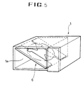
- a first holder 6' is fully inserted into the oven's cavity 1a thereby being diagonally seated in the rear portion inside the cavity 1a.
- a second holder 6' is fitted over one side portion of the glass tray 4. In this case, the side portion of the tray 4 is fully inserted into the slot 6c of the second holder 6'.
- one roller 5a of the rotating ring 5 is inserted into the roller holding notch 6e of the second holder 6'.
- the second holder 6' holding both the tray 4 and the rotating ring 5, is diagonally inserted into the cavity 1a in order to insert the other side portion of the tray 4 into the slot 6c of the first holder 6' at the same time of inserting another roller 5a of the rotating ring 5 into the slot 6c of the first holder 6'. Therefore, the tray 4 and rotating ring 5 are stably and tightly held by the two holders 6' inside the cavity 1a.
- the length of the holder is nearly equal to the diagonal length of the cavity 1a, so that the holder 6, 6' is brought into close contact with diagonally-opposite corners of the cavity 1a, thereby being prevented from moving inside the cavity 1a.
- the bottom of the glass tray 4 is tightly held by the bottom seat part of the holder, while the top of the tray 4 is covered with the upper flaps 6f.
- the diametrically-opposite side portions of the tray 4 are tightly inserted into the slots 6c, so that the tray 4 is stably seated in the side holder parts.
- the rollers 5a of the rotating ring 5 are inserted in the roller holding notches 6e of the upper flaps 6f, so that the rotating ring 5 is also stably and tightly held by the holder 6, 6'.
- the holder 6, 6' of this invention thus stably holds the oven's internal elements (the glass tray 4 and rotating ring 5) inside the cavity 1a of a packaged microwave oven 1, so that the holder 6, 6' prevents the internal elements from moving inside the cavity 1a even when the packaged oven 1 is carelessly impacted or vibrated while the packaged oven 1 is handled during transportation of the oven 1.
- the present invention provides a structurally-improved holder for the internal elements of a packaged microwave oven.
- the holder of this invention has a simple construction and stably holds the oven's internal elements in their positions inside the oven's cavity.
- the above holder can be recycled, so that the holder does not cause any environmental pollution.
Landscapes
- Engineering & Computer Science (AREA)
- Mechanical Engineering (AREA)
- Constitution Of High-Frequency Heating (AREA)
- Packaging Frangible Articles (AREA)
- Packages (AREA)
- Packaging Of Machine Parts And Wound Products (AREA)
Claims (5)
- Halter für innere Elemente eines verpackten Mikrowellenherdes, wie beispielsweise eine Glasschale (4) und einen sich drehenden Ring (5) mit einer Rolle (5a) mit:einem Bodenaufnahmeteil (6a, 6b) zum Halten des Bodens der Glasschale (4),wenigstens zwei Halteklappenteilen (6f, 6f'), die am Bodenaufnahmeteil (6a, 6b) vorgesehen sind, um die Oberseite der Glasschale (4), die im Bodenaufnahmeteil (6a, 6b) sitzt, zu überdecken, undzwei Seitenhalterteilen (6d, 6d') zum festen Aufnehmen und Halten der diametral gegenüber liegenden Seitenteile der Glasschale (4),wobei die Halteklappenteile (6f, 6f')eine untere Halteklappe (6f') undeine obere Halteklappe (6f) umfassen, die die Oberseite der unteren Halteklappe (6f') überdeckt, dadurch gekennzeichnet, daß die obere Halteklappe (6f) mit einer Rollenhaltekerbe (6e) zum Halten der Rolle (5a) des sich drehenden Rings (5) versehen ist.
- Halter nach Anspruch 1, bei dem die Seitenhalterteile (6d, 6d') auf beiden Seiten des Bodenaufnahmeteils (6a, 6b) vorgesehen sind, wobei jeder der Seitenhalterteile (6d, 6d')
innere und äußere Seitenwände umfasst, welche innere Seitenwand mit einem Halteschlitz (6c) zur Aufnahme eines Seitenteils der Glasschale (4) versehen ist, während die äußere Seitenwand eine Seitenwand des Halters bildet. - Halter nach Anspruch 1 oder 2, bei dem der Bodenaufnahmeteil (6a, 6b)zwei Außenaufnahmen, die die diametral gegenüber liegenden Seitenbodenteile der Glasschale (4) halten können, undeine Innenaufnahme umfasst, die einen mittleren Bodenteil der Schale (4) halten kann.
- Halter nach Anspruch 3, bei dem die Innenaufnahme zwei halbkreisförmige Elemente umfasst, welche halbkreisförmigen Elemente sich von den jeweiligen Außenaufnahmen nach innen erstrecken und über einen mittleren Steg miteinander verbunden sind.
- Halter nach Anspruch 1, 2, 3 oder 4, welcher Halter aus Wellpappe besteht.
Applications Claiming Priority (4)
| Application Number | Priority Date | Filing Date | Title |
|---|---|---|---|
| KR9548317 | 1995-12-11 | ||
| KR1019950048317A KR100206765B1 (ko) | 1995-12-11 | 1995-12-11 | 전자렌지의 내장물 고정부재 |
| KR1019950048728A KR100206766B1 (ko) | 1995-12-12 | 1995-12-12 | 전자렌지의 내장물 고정구조 |
| KR9548728 | 1995-12-12 |
Publications (2)
| Publication Number | Publication Date |
|---|---|
| EP0779224A1 EP0779224A1 (de) | 1997-06-18 |
| EP0779224B1 true EP0779224B1 (de) | 2001-10-10 |
Family
ID=26631474
Family Applications (1)
| Application Number | Title | Priority Date | Filing Date |
|---|---|---|---|
| EP96118529A Expired - Lifetime EP0779224B1 (de) | 1995-12-11 | 1996-11-19 | Verpackung für Teile eines Microwellenofens |
Country Status (6)
| Country | Link |
|---|---|
| US (1) | US5786580A (de) |
| EP (1) | EP0779224B1 (de) |
| CN (1) | CN1112306C (de) |
| BR (1) | BR9605964A (de) |
| DE (1) | DE69615801T2 (de) |
| IN (1) | IN192211B (de) |
Families Citing this family (14)
| Publication number | Priority date | Publication date | Assignee | Title |
|---|---|---|---|---|
| US6412635B1 (en) * | 2000-06-30 | 2002-07-02 | Cisco Technology, Inc. | Non-orthogonal packing method and apparatus |
| KR100465191B1 (ko) * | 2002-02-06 | 2005-01-13 | 삼성전자주식회사 | 전자렌지 |
| FR2921048A1 (fr) * | 2007-09-19 | 2009-03-20 | Nidatec Soc Par Actions Simpli | Organe de calage d'un appareil de cuisson comportant une cuve et un couvercle et emballage comprenant un tel organe |
| JP5902450B2 (ja) * | 2011-11-28 | 2016-04-13 | 株式会社ハーマン | グリル包装材およびそれを用いたグリルの包装構造 |
| JP6293022B2 (ja) * | 2014-09-01 | 2018-03-14 | シャープ株式会社 | 加熱調理器用梱包構造 |
| US9955534B2 (en) | 2015-05-15 | 2018-04-24 | Ck Innovative Microwave Products Llc | Microwave tray and accessories |
| CN105501674B (zh) * | 2015-12-09 | 2017-10-31 | 许昌学院 | 一种飞镖盘的集展示性与可运输性为一体的衬盒 |
| CN105800027B (zh) * | 2016-04-22 | 2019-02-05 | 广东格兰仕微波炉电器制造有限公司 | 烤架的包装结构 |
| CN105775309A (zh) * | 2016-04-22 | 2016-07-20 | 广东格兰仕微波炉电器制造有限公司 | 转盘的包装结构 |
| USD794388S1 (en) | 2016-05-12 | 2017-08-15 | Ck Innovative Microwave Products Llc | Microwave tray with a removable center portion |
| CN108910213A (zh) * | 2018-05-28 | 2018-11-30 | 合肥市裕同印刷包装有限公司 | 一种刀卡模具码垛机构 |
| CN110104335B (zh) * | 2019-06-10 | 2021-03-02 | 河南科技大学 | 用于玻璃套装茶具的便携式仿形结构 |
| US11724867B2 (en) | 2021-11-22 | 2023-08-15 | Whirlpool Corporation | Reconfigurable packaging and corresponding blank |
| WO2024063706A1 (en) * | 2022-07-19 | 2024-03-28 | Femas Metal San. Ve Tic. A.S. | Packaging element for an oven |
Family Cites Families (11)
| Publication number | Priority date | Publication date | Assignee | Title |
|---|---|---|---|---|
| US2997164A (en) * | 1958-11-24 | 1961-08-22 | West Virginia Pulp & Paper Com | Container for packaging grinding wheels |
| CH444338A (de) * | 1965-05-19 | 1967-09-30 | Patelhold Patentverwertung | Mikrowellenbehandlungsgerät zum Erwärmen von Flüssigkeiten, insbesondere von Blutkonserven |
| US3752301A (en) * | 1971-02-22 | 1973-08-14 | O Bluemel | Shock-proof packing container |
| US4033009A (en) * | 1975-01-27 | 1977-07-05 | Sage Laboratories, Inc. | Handles for supporting a dish or the like in a microwave oven |
| CH662407A5 (fr) * | 1985-01-25 | 1987-09-30 | Nestle Sa | Procede et dispositif pour le rechauffement d'aliments par micro-ondes. |
| US4698472A (en) * | 1986-09-08 | 1987-10-06 | Golden Valley Microwave Foods Inc. | Microwave heating stand with electrically isolated reflector |
| US4965424A (en) * | 1989-05-25 | 1990-10-23 | Mass Market Sales, Inc. | Disposable food container for microwave ovens |
| US5232095A (en) * | 1991-04-16 | 1993-08-03 | American Sterilizer Company | Shipping apparatus with diagonally rotatably mounted contents |
| DE9217901U1 (de) * | 1992-12-30 | 1993-04-15 | Schwerdtle & Schantz GmbH, 1000 Berlin | Verpackung für einen scheibenförmigen Aufzeichnungsträger |
| US5493103A (en) * | 1993-12-27 | 1996-02-20 | Kuhn; James O. | Baking utensil to convert microwave into thermal energy |
| KR960013946A (ko) * | 1994-10-21 | 1996-05-22 | 이헌조 | 전자레인지의 내장물 포장장치 |
-
1996
- 1996-11-19 DE DE69615801T patent/DE69615801T2/de not_active Expired - Fee Related
- 1996-11-19 EP EP96118529A patent/EP0779224B1/de not_active Expired - Lifetime
- 1996-11-20 US US08/752,927 patent/US5786580A/en not_active Expired - Fee Related
- 1996-11-21 IN IN2020CA1996 patent/IN192211B/en unknown
- 1996-12-11 CN CN96123110.6A patent/CN1112306C/zh not_active Expired - Fee Related
- 1996-12-11 BR BR9605964A patent/BR9605964A/pt not_active IP Right Cessation
Also Published As
| Publication number | Publication date |
|---|---|
| CN1159544A (zh) | 1997-09-17 |
| IN192211B (de) | 2004-03-20 |
| DE69615801T2 (de) | 2002-06-13 |
| CN1112306C (zh) | 2003-06-25 |
| BR9605964A (pt) | 1998-08-18 |
| EP0779224A1 (de) | 1997-06-18 |
| DE69615801D1 (de) | 2001-11-15 |
| US5786580A (en) | 1998-07-28 |
Similar Documents
| Publication | Publication Date | Title |
|---|---|---|
| EP0779224B1 (de) | Verpackung für Teile eines Microwellenofens | |
| US5076491A (en) | Box of corrugated fibreboard and packaging method | |
| US5988370A (en) | Corrugated fibreboard container with at least one hinged side and blanks for assembling said container | |
| GB2317879A (en) | Blank for box with integral interior object supports | |
| EP0498894A1 (de) | Wellpappe-transportkarton für gross-fernsehempfänger | |
| US5988389A (en) | Article cradle | |
| US4971242A (en) | Multiple container assembly | |
| US5823421A (en) | Cardboard or like articles | |
| US20040232025A1 (en) | Wet canvas carrier | |
| JPH02242759A (ja) | 可変高さの端パネルを備えた巻付式物品キヤリヤ | |
| JPH0542948A (ja) | トレイ用包装箱 | |
| JPH05201433A (ja) | 梱包材 | |
| JP3243343B2 (ja) | 中仕切り付き容器 | |
| JPS593931Y2 (ja) | 梱包箱 | |
| JPH08258835A (ja) | 化粧箱内の緩衝用具 | |
| JPH1179161A (ja) | 間仕切り具 | |
| EP0410529A1 (de) | Verpackung für einen zerbrechlichen zylindrischen Gegenstand | |
| GB2087358A (en) | Storage and transport container | |
| KR200171773Y1 (ko) | 계란재치판과 골판지를 이용한 계란포장상자 | |
| KR200250096Y1 (ko) | 음식물 저장용기 | |
| KR200235934Y1 (ko) | 진열용상자로사용할수있는포장상자 | |
| JP2541555Y2 (ja) | ケース | |
| JP2000185731A (ja) | フィルムケース | |
| GB2221448A (en) | Box pallets | |
| JP3859276B2 (ja) | 包装構造 |
Legal Events
| Date | Code | Title | Description |
|---|---|---|---|
| PUAI | Public reference made under article 153(3) epc to a published international application that has entered the european phase |
Free format text: ORIGINAL CODE: 0009012 |
|
| AK | Designated contracting states |
Kind code of ref document: A1 Designated state(s): DE FR GB |
|
| 17P | Request for examination filed |
Effective date: 19971217 |
|
| 17Q | First examination report despatched |
Effective date: 19991227 |
|
| GRAG | Despatch of communication of intention to grant |
Free format text: ORIGINAL CODE: EPIDOS AGRA |
|
| GRAG | Despatch of communication of intention to grant |
Free format text: ORIGINAL CODE: EPIDOS AGRA |
|
| GRAH | Despatch of communication of intention to grant a patent |
Free format text: ORIGINAL CODE: EPIDOS IGRA |
|
| GRAH | Despatch of communication of intention to grant a patent |
Free format text: ORIGINAL CODE: EPIDOS IGRA |
|
| GRAA | (expected) grant |
Free format text: ORIGINAL CODE: 0009210 |
|
| AK | Designated contracting states |
Kind code of ref document: B1 Designated state(s): DE FR GB |
|
| REF | Corresponds to: |
Ref document number: 69615801 Country of ref document: DE Date of ref document: 20011115 |
|
| REG | Reference to a national code |
Ref country code: GB Ref legal event code: IF02 |
|
| ET | Fr: translation filed | ||
| PLBE | No opposition filed within time limit |
Free format text: ORIGINAL CODE: 0009261 |
|
| STAA | Information on the status of an ep patent application or granted ep patent |
Free format text: STATUS: NO OPPOSITION FILED WITHIN TIME LIMIT |
|
| 26N | No opposition filed | ||
| PGFP | Annual fee paid to national office [announced via postgrant information from national office to epo] |
Ref country code: DE Payment date: 20071115 Year of fee payment: 12 |
|
| PGFP | Annual fee paid to national office [announced via postgrant information from national office to epo] |
Ref country code: GB Payment date: 20071114 Year of fee payment: 12 Ref country code: FR Payment date: 20071108 Year of fee payment: 12 |
|
| GBPC | Gb: european patent ceased through non-payment of renewal fee |
Effective date: 20081119 |
|
| REG | Reference to a national code |
Ref country code: FR Ref legal event code: ST Effective date: 20090731 |
|
| PG25 | Lapsed in a contracting state [announced via postgrant information from national office to epo] |
Ref country code: DE Free format text: LAPSE BECAUSE OF NON-PAYMENT OF DUE FEES Effective date: 20090603 |
|
| PG25 | Lapsed in a contracting state [announced via postgrant information from national office to epo] |
Ref country code: GB Free format text: LAPSE BECAUSE OF NON-PAYMENT OF DUE FEES Effective date: 20081119 |
|
| PG25 | Lapsed in a contracting state [announced via postgrant information from national office to epo] |
Ref country code: FR Free format text: LAPSE BECAUSE OF NON-PAYMENT OF DUE FEES Effective date: 20081130 |