EP0778758B1 - Method of creating a directed stream of droplets - Google Patents
Method of creating a directed stream of droplets Download PDFInfo
- Publication number
- EP0778758B1 EP0778758B1 EP95930586A EP95930586A EP0778758B1 EP 0778758 B1 EP0778758 B1 EP 0778758B1 EP 95930586 A EP95930586 A EP 95930586A EP 95930586 A EP95930586 A EP 95930586A EP 0778758 B1 EP0778758 B1 EP 0778758B1
- Authority
- EP
- European Patent Office
- Prior art keywords
- enclosure
- opening
- wall
- wall section
- treatment
- Prior art date
- Legal status (The legal status is an assumption and is not a legal conclusion. Google has not performed a legal analysis and makes no representation as to the accuracy of the status listed.)
- Expired - Lifetime
Links
Images


Classifications
-
- A—HUMAN NECESSITIES
- A61—MEDICAL OR VETERINARY SCIENCE; HYGIENE
- A61F—FILTERS IMPLANTABLE INTO BLOOD VESSELS; PROSTHESES; DEVICES PROVIDING PATENCY TO, OR PREVENTING COLLAPSING OF, TUBULAR STRUCTURES OF THE BODY, e.g. STENTS; ORTHOPAEDIC, NURSING OR CONTRACEPTIVE DEVICES; FOMENTATION; TREATMENT OR PROTECTION OF EYES OR EARS; BANDAGES, DRESSINGS OR ABSORBENT PADS; FIRST-AID KITS
- A61F9/00—Methods or devices for treatment of the eyes; Devices for putting-in contact lenses; Devices to correct squinting; Apparatus to guide the blind; Protective devices for the eyes, carried on the body or in the hand
-
- B—PERFORMING OPERATIONS; TRANSPORTING
- B05—SPRAYING OR ATOMISING IN GENERAL; APPLYING FLUENT MATERIALS TO SURFACES, IN GENERAL
- B05B—SPRAYING APPARATUS; ATOMISING APPARATUS; NOZZLES
- B05B11/00—Single-unit hand-held apparatus in which flow of contents is produced by the muscular force of the operator at the moment of use
- B05B11/0005—Components or details
- B05B11/0062—Outlet valves actuated by the pressure of the fluid to be sprayed
-
- A—HUMAN NECESSITIES
- A61—MEDICAL OR VETERINARY SCIENCE; HYGIENE
- A61F—FILTERS IMPLANTABLE INTO BLOOD VESSELS; PROSTHESES; DEVICES PROVIDING PATENCY TO, OR PREVENTING COLLAPSING OF, TUBULAR STRUCTURES OF THE BODY, e.g. STENTS; ORTHOPAEDIC, NURSING OR CONTRACEPTIVE DEVICES; FOMENTATION; TREATMENT OR PROTECTION OF EYES OR EARS; BANDAGES, DRESSINGS OR ABSORBENT PADS; FIRST-AID KITS
- A61F9/00—Methods or devices for treatment of the eyes; Devices for putting-in contact lenses; Devices to correct squinting; Apparatus to guide the blind; Protective devices for the eyes, carried on the body or in the hand
- A61F9/0008—Introducing ophthalmic products into the ocular cavity or retaining products therein
-
- A—HUMAN NECESSITIES
- A61—MEDICAL OR VETERINARY SCIENCE; HYGIENE
- A61M—DEVICES FOR INTRODUCING MEDIA INTO, OR ONTO, THE BODY; DEVICES FOR TRANSDUCING BODY MEDIA OR FOR TAKING MEDIA FROM THE BODY; DEVICES FOR PRODUCING OR ENDING SLEEP OR STUPOR
- A61M15/00—Inhalators
-
- B—PERFORMING OPERATIONS; TRANSPORTING
- B05—SPRAYING OR ATOMISING IN GENERAL; APPLYING FLUENT MATERIALS TO SURFACES, IN GENERAL
- B05B—SPRAYING APPARATUS; ATOMISING APPARATUS; NOZZLES
- B05B11/00—Single-unit hand-held apparatus in which flow of contents is produced by the muscular force of the operator at the moment of use
- B05B11/0005—Components or details
- B05B11/0027—Means for neutralising the actuation of the sprayer ; Means for preventing access to the sprayer actuation means
- B05B11/0032—Manually actuated means located downstream the discharge nozzle for closing or covering it, e.g. shutters
-
- B—PERFORMING OPERATIONS; TRANSPORTING
- B05—SPRAYING OR ATOMISING IN GENERAL; APPLYING FLUENT MATERIALS TO SURFACES, IN GENERAL
- B05B—SPRAYING APPARATUS; ATOMISING APPARATUS; NOZZLES
- B05B11/00—Single-unit hand-held apparatus in which flow of contents is produced by the muscular force of the operator at the moment of use
- B05B11/0005—Components or details
- B05B11/0062—Outlet valves actuated by the pressure of the fluid to be sprayed
- B05B11/0072—A valve member forming part of an outlet opening
-
- B—PERFORMING OPERATIONS; TRANSPORTING
- B05—SPRAYING OR ATOMISING IN GENERAL; APPLYING FLUENT MATERIALS TO SURFACES, IN GENERAL
- B05B—SPRAYING APPARATUS; ATOMISING APPARATUS; NOZZLES
- B05B17/00—Apparatus for spraying or atomising liquids or other fluent materials, not covered by the preceding groups
- B05B17/04—Apparatus for spraying or atomising liquids or other fluent materials, not covered by the preceding groups operating with special methods
- B05B17/06—Apparatus for spraying or atomising liquids or other fluent materials, not covered by the preceding groups operating with special methods using ultrasonic or other kinds of vibrations
- B05B17/0607—Apparatus for spraying or atomising liquids or other fluent materials, not covered by the preceding groups operating with special methods using ultrasonic or other kinds of vibrations generated by electrical means, e.g. piezoelectric transducers
-
- B—PERFORMING OPERATIONS; TRANSPORTING
- B05—SPRAYING OR ATOMISING IN GENERAL; APPLYING FLUENT MATERIALS TO SURFACES, IN GENERAL
- B05B—SPRAYING APPARATUS; ATOMISING APPARATUS; NOZZLES
- B05B9/00—Spraying apparatus for discharge of liquids or other fluent material, without essentially mixing with gas or vapour
- B05B9/03—Spraying apparatus for discharge of liquids or other fluent material, without essentially mixing with gas or vapour characterised by means for supplying liquid or other fluent material
- B05B9/04—Spraying apparatus for discharge of liquids or other fluent material, without essentially mixing with gas or vapour characterised by means for supplying liquid or other fluent material with pressurised or compressible container; with pump
- B05B9/08—Apparatus to be carried on or by a person, e.g. of knapsack type
- B05B9/0805—Apparatus to be carried on or by a person, e.g. of knapsack type comprising a pressurised or compressible container for liquid or other fluent material
- B05B9/0838—Apparatus to be carried on or by a person, e.g. of knapsack type comprising a pressurised or compressible container for liquid or other fluent material supply being effected by follower in container, e.g. membrane or floating piston, or by deformation of container
-
- B—PERFORMING OPERATIONS; TRANSPORTING
- B65—CONVEYING; PACKING; STORING; HANDLING THIN OR FILAMENTARY MATERIAL
- B65D—CONTAINERS FOR STORAGE OR TRANSPORT OF ARTICLES OR MATERIALS, e.g. BAGS, BARRELS, BOTTLES, BOXES, CANS, CARTONS, CRATES, DRUMS, JARS, TANKS, HOPPERS, FORWARDING CONTAINERS; ACCESSORIES, CLOSURES, OR FITTINGS THEREFOR; PACKAGING ELEMENTS; PACKAGES
- B65D75/00—Packages comprising articles or materials partially or wholly enclosed in strips, sheets, blanks, tubes, or webs of flexible sheet material, e.g. in folded wrappers
- B65D75/52—Details
- B65D75/58—Opening or contents-removing devices added or incorporated during package manufacture
-
- B—PERFORMING OPERATIONS; TRANSPORTING
- B65—CONVEYING; PACKING; STORING; HANDLING THIN OR FILAMENTARY MATERIAL
- B65D—CONTAINERS FOR STORAGE OR TRANSPORT OF ARTICLES OR MATERIALS, e.g. BAGS, BARRELS, BOTTLES, BOXES, CANS, CARTONS, CRATES, DRUMS, JARS, TANKS, HOPPERS, FORWARDING CONTAINERS; ACCESSORIES, CLOSURES, OR FITTINGS THEREFOR; PACKAGING ELEMENTS; PACKAGES
- B65D83/00—Containers or packages with special means for dispensing contents
- B65D83/14—Containers or packages with special means for dispensing contents for delivery of liquid or semi-liquid contents by internal gaseous pressure, i.e. aerosol containers comprising propellant for a product delivered by a propellant
- B65D83/44—Valves specially adapted therefor; Regulating devices
Definitions
- This invention relates to a method of creating a directed jet and/or stream of droplets forming a unit dose of treatment liquid.
- Ophthalmic treatment fluids are commonly administered to the eye by means of eye drops or ointments.
- eye drops has a number of disadvantages, primarily as a consequence of the difficulty with which drops are accepted by the patient.
- the drops are relatively large, and the instinctive blink that is provoked by the arrival of a drop on the eye severely limits the amount of or proportion of fluid that actually contacts the target area on the eye.
- Typically less than 10% of a 50 ⁇ l drop can be effective, the remainder being lost by drainage, either externally or through nasolacrimal drainage.
- Such use of expensive treatment fluids is wasteful, as well as leading to substantial uncertainty regarding the effectiveness of a treatment.
- Similar comments apply to the use of ointments, although levels of wastage can be reduced by careful delivery. The greater viscosity of ointments reduces their tendency to drain or be washed away.
- GB-A-2 255 918 discloses a method for delivering a fluid as a spray of droplets forming a unit dose of treatment fluid discharged from a sealed enclosure through an opening in the wall thereof. This opening has a diameter less than 100 ⁇ m, preferably 1 to 20 ⁇ m.
- the present invention provides a method of creating a directed jet and/or stream of droplets with a minimum diameter of 20 ⁇ m and sufficient momentum to sustain substantially linear movement over a predetermined distance.
- the wall section of the container formed with the opening or openings is typically a flat section of the enclosure wall, and the enclosure is typically a blister pack, with the wall section at a planar base of the blister.
- the adoption of a non-planar wall section in which the opening or openings are formed More particularly, we have found that the adoption of a dome shape in the respective wall section can result in a more reliable performance of the containers in use, and facilitate certain other beneficial developments of the containers.
- a unit container for a treatment fluid comprising an enclosure of which one wall section is dome shaped and formed with at least one opening in the top region of the dome shape, the enclosure being adapted to confine a sealed volume of treatment fluid, and pressurisable to discharge the contents of the sealed volume through said at least one opening.
- One or more other wall sections may also define a dome shape complementary to that with the opening, which is capable of inversion into the one wall section in the discharge of the container contents.
- the enclosure of the unit container can be pressurised by the application of an external force on the side of the enclosure opposite the wall section formed with the opening or openings.
- this method of pressurising the enclosure contents can create high stresses in the wall section, and particularly around the opening or openings. In some situations, this can result in the wall section itself tearing around the opening or openings with the consequence that the discharge of the enclosure contents becomes less predictable. By locating the opening or openings at the top of a dome shape, these stresses are reduced.
- Either a single opening or an array of openings may be found in the respective wall section of the container.
- Various arrays are possible, and a particular choice will be influenced by a number of factors.
- a larger number of openings will dispense treatment fluid over a larger target area.
- Smaller openings produce narrower jets and/or smaller drops which will be subject to greater deceleration in their passage to the target area. This may allow the use of higher pressures.
- a single opening can direct a jet or stream of drops accurately to a specific target area, and minimise the time taken to deliver the treatment fluid to beat the blink response.
- the use of a single opening of 100 ⁇ m diameter is particularly preferred. The intention is to create droplets no smaller than say 20 ⁇ m to avoid the creation of an inhalable spray.
- dome shaped wall section in which the opening or openings are defined is that discharge of substantially the entire contents of the enclosure is facilitated.
- the device used to pressurise the enclosure is a piston or hammer, its operative end can be shaped to complement that of the dome such that in operation the other wall sections of the enclosure, which can similarly be shaped to complement that of the dome, are inverted against the dome shaped wall section thus substantially evacuating the entire enclosure.
- the wall section of the enclosure may be provided with a removable cover overlaying the opening or openings, which cover is only removed just prior to the contents of the enclosure being discharged. In this way, the contents are protected from the environment until required.
- the or each opening in the wall section of the enclosure is closed by a membrane adapted to rupture upon pressurisation of the enclosure.
- a dome wall section facilitates the creation of a separate sealed volume within the enclosure.
- the removable cover overlaying the opening or openings can be dispensed with, or at least the requirements for its sealing qualities can be reduced.
- a dividing wall is included within the enclosure, which dividing wall separates the wall section with the opening or openings from a region within the enclosure which defines the sealed volume. The dividing wall is adapted to rupture prior to discharge of the contents from the enclosure.
- the dividing wall can be adapted to rupture upon pressurisation of the enclosure as part of the step of discharging the contents of the sealed volume through the opening or openings in the wall section.
- the dividing wall may be adapted to rupture upon the application of an external force prior to pressurisation of the enclosure.
- a mechanism can be included to apply tensile force across the container to break the dividing wall just prior to the enclosure being pressurised.
- the container defines a sealed volume with a dividing wall
- this sealed volume can be formed as a individual component of the container prior to attachment of the wall section formed with the opening or openings.
- This feature also offers a number of particular benefits, primarily in the manufacture of packages containing a plurality of complete containers. Manufacturing these components individually means they can be separately checked for defects prior to incorporation in a package. It also facilitates the creation of packages having containers with different dosages; either different treatment fluids or different quantities of the same fluid, and also enables a plurality of individual components to be disposed under a common dome shaped wall section, whereby different treatment fluids can be kept isolated, but mixed just prior to discharge from the opening or openings.
- the containers are designed to provide for the successive or simultaneous delivery of a jet or small droplets, sometimes in the form of a stream or spray, which may be diffuse or collinear.
- a typical range for the size of opening in the wall section of the enclosure to achieve is up to 1000 ⁇ m, preferably 20 to 200 ⁇ m.
- a particularly preferred size range is 100 to 150 ⁇ m.
- a single opening or an array of openings can be used, conveniently punched, drilled, electroformed or laser-drilled in a plastics sheet or foil defining the wall section.
- a metal, typically a nickel foil is preferred for electroforming.
- the containers can be charged such that each enclosure confines a prescribed unit dose for discharge therefrom, typically no more than 10 ⁇ l. However, larger volumes such as 20, 50 or 100 ⁇ l could be required, for example for irrigation purposes.
- a plurality of containers may be provided in the form of a package, conveniently on a common substrate, and preferably in the form of a strip with the containers arranged sequentially therealong.
- the discharge of the contents of enclosures in the container can most simply be accomplished by provoking the collapse of the enclosure wall, against the section having the opening or openings, preferably by a mechanical system.
- the wall may include a reinforced region to orient its collapse.
- the enclosure might be crushed from the side opposite the wall section by a piston, hammer or cantilever mechanism, the action of which may be dampened to control the speed of the mechanism, with sufficient impact to discharge and project the contents a predetermined minimum distance.
- the enclosure might be formed as a cylindrical chamber, with an opposite wall portion formed as a piston for movement towards the wall section to force the enclosure contents through the opening or openings.
- Such a device comprises a package of the containers; a mechanism for feeding the containers seriatim to a dosing station; and means for acting on the enclosure of a container at the dosing station to discharge the contents thereof.
- a manual feed device in which provision is made for individual containers or packages thereof to be fed manually to the dosing station as required.
- the device can include means for its removal prior to discharge of the enclosure contents. This means may be synchronised with the feeding mechanism.
- the discharge of the contents of the enclosure at the dosing station in the above device is preferably accomplished by pressure such that it is forced through the opening or openings in the respective wall section of the enclosure.
- an electrostatic technique can be used, broadly of the kind described in published European Patent Specification No. 0 224 352.
- a modified unit container in which the enclosure is not specifically pressurisable, but has a wall which includes a conductive section for connection to a source of electrical potential, whereby application of such potential generates an electrical charge in the container contents, and its discharge through said at least one opening.
- the preferred means is a physical mechanism such as a crushing unit for acting directly on the outside of the enclosure from the side opposite the wall section formed with the opening or openings.
- This can take the form of a piston-cylinder mechanism, and such a mechanism can also be used to move an opposite wall portion in a cylindrical enclosure of the kind described above.
- piezoelectric elements Another technique that can be used to pressurise the enclosure in the containers uses piezoelectric elements. Such elements enable the degree of pressurisation achieved to be accurately controlled, and can be disposed for example, against a face of the enclosure opposite the wall section,or in the form of a ring around the body of the enclosure. In either arrangement such an element can be operated selectively or repeatedly to discharge discrete droplets or a rapid sequence.
- the element may take the form of an ultrasonic transducer, one which is particularly suited to the generation of a spray through an array of openings in the wall section of the enclosure.
- a light can be provided to maintain the eye open, and this could typically be white.
- a coloured system may be employed in which a different colour indicates the stage of treatment.
- the device can be offered up to the eye showing a red light, which will switch to green only after the predetermined dose has been dispatched.
- Devices can also include a number of safety features which are already well established in dosing devices of various kinds.
- the number of containers in a device will of course be finite, and a dose recorder may be included to provide an indication of the number of doses remaining or delivered.
- a delay mechanism can also be included to prevent the inadvertent delivery of a multiple dose. In combination with the delivery signal features referred to above, this can be of significant benefit.
- the devices can be for personal or hand held use, or for use on a more regular basis in institutions.
- means can be provided for ensuring a proper spacing between the device and the eye to be targeted, and this can be made adjustable, particularly in the devices adapted for institutional use.
- the mechanisms contemplated will be well capable of discharging a jet and/or droplets substantially horizontally or vertically upwards over a minimum distance, thereby not requiring a user to arrange for the device to be operated from directly above an eye.
- the present invention thus provides methods of generating jets and/or droplets and of treatment, using such containers and devices.
- the methods additionally require the targeting of generated jets and/or droplets at a respective treatment site.
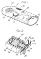
- the device shown in Figure 1 comprises a housing 2 with an open cowling 4 at one end with the dosing station 6 of the device disposed at the base thereof.
- the device shown is for ophthalmic treatment, and the cowling serves to ensure that the dosing station is located correctly and spaced a proper distance from the eye for a treatment to be effective.
- Containers according to the invention are mounted on a tape 8 which extends from a supply cord 10, around in front of the dosage station 6 and on to a take-up reel 12.
- a capstan 14 is provided to wind the tape on to locate a fresh container at the dosage station for discharge of its contents.
- a button 16 is shown for initiating the activation of the dosage station when it is properly charged.
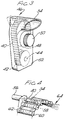
- each container on the tape 8 takes the form of a blister pack 18 depending from a continuous backing 20, as is better shown in Figure 2.
- the open face of the blister pack 18 is closed by a continuous metal foil 22, and over each blister the foil has ten 40 micron openings electroformed therein.
- Overlaying the foil is a cover layer 24, which is progressively removed from the foil as a blister pack reaches the dosage station 6. It is removed by a spring loaded take-up reel 26, which draws the cover layer around a guide bar 28 on the upstream side of the dosage station.
- a similar guide bar 28 is located on the downstream side of the dosage station, and the tape 8 is held thereagainst by means of spring loaded beams 30. These beams 30 are spaced by a distance substantially equal to the dimension of the blister 18 along the length of the tape 8 such that they also serve to locate the blister centrally at the dosage station 6.
- the dosage station shown in Figure 2 includes a piston 32 in a block 34, which is itself mounted in a housing 36 and located therein by means of a latch 38.
- the button 16 is depressed to release a spring (not shown) which charges the piston 32 against the blister 18, and crushes it against the foil 22.
- the capstan 14 is then turned to bring the next charged blister into alignment with the piston, and the capstan 14 will also be coupled to the piston 32 to retract it to its starting position prior to the fresh charged blister reaching its discharge position.
- the container enclosures 40 are mounted on a bandolier 42 which, as with the embodiment of Figure 1, extends from a supply reel 44 past a dosage station 46 and on to a take-up reel 48 coupled to a capstan 50 for winding on.
- the housing 52 has a cowling 54, but it will be noted that the orientation of the housing relative to the cowling is different.
- each enclosure 40 is successively aligned with the piston 54 of the cylinder mechanism 56.
- Each enclosure 40 is cylindrical, and has at its forward end a nozzle 58 with one or a plurality of openings therein. This end is closed by a foil seal 60.
- the other end of the enclosure 40 is closed by a silicone piston 62, and when the dosage station is activated the piston 54 engages the piston 62 and thus compresses enclosure contents. This pressure forces the contents through the opening or openings 58, simultaneously discarding the foil seal 60, and the contents are then discharged in the form of a spray as indicated at 64.
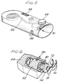
- FIG. 5 and 6 The device shown in Figures 5 and 6 is in some ways similar to that of Figures 1 and 2, but in this embodiment discharge is effected by means of a piezoelectric element.
- a tape 66 comprising discrete containers is wound on by means of a capstan 68 to locate a container at the dosage station 70.
- the enclosure 72 of the container is aligned with a piezoelectric ring transducer 74 while a cover layer 76 is removed in substantially the same manner as it is in the embodiment of Figure 1. Removal of the cover again exposes a metal foil 78 overlaying the blister 72 and formed with ten 40 micron electroformed openings.
- the dosage station illustrated in Figure 2 in this embodiment it comprises a piston 80 mounted in a cylinder 82 itself located in a housing 84 by means of a latch 86. Depression of the button 88 activates a spring to move the piston towards the blister 72, but only to locate the piezoelectric ring transducer 74 around the body thereof. Means (not shown) then activate the transducer 74 to contract it around the blister 72 and thus discharge the contents thereof through the openings in the metal foil.
- winding the tape on with the capstan 68 also retracts the piston 80.
- the capstan 68 also actuates a knife to detach the used blister from the tape 66, which is then ejected through an opening 88 in the device housing.
- FIGs 7 and 8 illustrate what can be regarded as a simplified version of the embodiment of Figures 5 and 6.
- the containers are provided separately, and the housing 90 of the device is provided with a storage compartment 92 for the container supply.
- a container 94 When the device is to be used, a container 94 must be removed from the storage compartment 92 and manually fitted to the ring transducer 96 fixed at the base of the cowling 98 of the housing.
- a battery 100 and the requisite electronics 102 are disposed in a chamber 104 located between the storage compartment 92 and the transducer 96.
- a cover 106 is removed from the visible face of the container 94 to expose a wall section 108 of the enclosure formed with a 50 micron nozzle.
- the electronics 102 When the electronics 102 are activated by a button (not shown) the ring transducer 96 contracts around the container 94 to discharge its contents through the nozzle.
- the enclosure of the container 94 is reinforced around its inner perimeter by a section 110. This inhibits rupture of the enclosure upon contraction of the ring transducer, and its internal shape also serves to increase the discharge velocity of fluid from the enclosure through the nozzle.
- FIGS 9 and 10 illustrate an alternative embodiment of the invention in which the contents of the enclosure are discharged by means of an electrostatic charging system.
- a covered strip 112 of containers 114 is provided in the housing 116, with a capstan 118 for advancing the strip 112 to locate a container 114 at the dosing station 120, broadly in the manner described with reference to Figures 1 and 2.
- the enclosures 122 of the containers 114 are formed of an electrically conductive material.
- a contact 124 is located at the dosing station 120 to engage the enclosure wall, and a switch (not shown), activated by the dispense button 126 is provided to apply an electrical potential from a generator 128 to the enclosure wall to charge the contents and force their discharge through the opening 130.
- Power for the generator 128 is provided by a battery 132, also located in the housing 116. Because the enclosure wall in each container is conductive, they must be isolated from each other in the strip 112. Thus, as shown in Figure 10, the strip has an insulating section 134 between the containers 114.
- containers enclosing different fluids can be included for feeding to the dosing station, and where the containers are mounted on a strip or bandolier, then a chosen sequence can be predetermined.
- an anaesthetic or diagnostic aid such as fluorescein might be enclosed in alternate containers mounted on a strip.
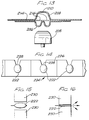
- FIGs 11 to 13 illustrate preferred containers for use in the devices described above, which are of "double-dome" construction.
- the container shown in Figure 11 defines an enclosure 202 in which is held a quantity of treatment fluid 204.
- the lower part of the container as shown is created as a blister in a foil laminate base sheet 206 which is overlaid with a foil laminate upper sheet 208 which is formed into a dome where it defines the upper part of the enclosure 202.
- the base and upper sheets 206, 208 are bonded where they contact one another to seal the enclosure at the junction therebetween.
- an opening 210 In the top section of the upper sheet 208 is formed an opening 210, which is closed by a cover sheet 212 making sealing engagement with the external surface of the upper sheet 208 around the opening 210.
- the cover sheet 212 is typically a plastics sheet or a metal foil.
- the container shown in Figure 11 is fitted in a device which properly locates the enclosure 202 relative to means such as a piston or air pressure source, for forcing the base sheet 206 where it forms the lower part of the enclosure 202, towards the opening 210 and against the upper sheet 208.
- means such as a piston or air pressure source, for forcing the base sheet 206 where it forms the lower part of the enclosure 202, towards the opening 210 and against the upper sheet 208.
- the cover sheet 212 is removed, and the system actuated.
- the treatment fluid 204 in the enclosure 202 is discharged through the opening 210 towards its chosen target.
- Figures 12 illustrate a container in which individual components of the container can be prepared separately with treatment fluid therein, and thereafter attached to an upper sheet which completes the respective containers.
- a component is shown in Figure 12A, which consists of a base sheet 206 formed into a blister to hold a quantity fluid 204.
- the blister is closed by an intermediate layer 214 sealed around the periphery of the blister to the base sheet, but including a weakened section 216 which actually overlays the blister. Nevertheless, the component illustrated is sealed, and the treatment fluid 204 in the blister is properly protected from contact with the external atmosphere. It also allows autoclave sterilisation of the sealed volume.
- Figure 12B shows a section of upper sheet 208 formed with an opening 210 for disposal over the blister of the component shown in Figure 12. The assembled combination is shown in Figure 12C.
- Each component shown in Figure 12A is manufactured as a discrete element, and may be subject to quality control examination to ensure that as a treatment fluid dosage component, it is sound in every particular.
- an upper sheet 208 is laid and sealed thereover with its domed section including the opening 210 disposed directly opposite the blister in which the treatment fluid 204 is held. If a strip of containers is to be formed, then a continuous length of upper sheet 208 formed with a series of domed sections can be used to simultaneously complete and interconnect a package of containers according to the invention. Such a package is illustrated in Figure 12C.
- a container of the type illustrated as part of the package of Figure 12C is generally similar to that of Figure 11, with two essential differences. Firstly, a cover sheet 212 is not essential because the treatment fluid 204 is already sealed within the volume defined within the container by the layer 214. Nevertheless, some form of cover sheet might still be used, although it will be understood that the bond between the cover sheet 212 and the upper sheet 208 around the holes 210 does not have to be effective to seal the enclosure to the same extent as it does in the embodiment of Figure 11.
- the first effect is the rupturing of the weakened section 216 of the layer 214, and the weakened section 216 may be designed to rupture along a defined axis. Thereafter, the discharge is essentially similar to that of the embodiment of Figure 11.
- the weakened section 216 may also absorb some of the crushing force during the collapse of the blister, resulting in lower pressures and a reduced tendency of the blister or dome to burst or tear.
- the discharge device used can be adapted such that the laminate of base and upper sheets 206, 208, and layer 214 is gripped on either side of the blister, and stretched across the blister to rupture the weakened section 216 before a piston for example, engages the base sheet 206 to collapse the enclosure.
- the direction of such stretching is indicated by the arrows shown adjacent the container shown on the left-hand side of Figure 12C.
- Figure 13 shows a container in which two treatment fluids can be confined separately in the same enclosure, within respective sealed volumes closed by weakened sections of an intermediate layer 214.
- the manufacture, assembly and use of the container is essentially similar to those described with reference to Figures 12, but Figure 13 also illustrates a piston or hammer 218 for effecting discharge of the treatment fluids through the opening 210.
- the shapes of the blister in the sheet 206 and the dome in the sheet 208 can be made complementary such that when a piston such as 218 is applied to the blister, or blisters as shown in Figure 13, the entire section of sheet defining the blister or blisters eventually engages the section of sheet defining the dome to substantially completely evacuate the enclosure of the treatment fluid or fluids previously contained therein. This of course is particularly important in treatments where dosages must be accurately defined.
- a foil laminate upper sheet 208 can be used in which only a single opening 210 is formed.
- the preferred material for the upper sheet 208 is a metal foil in which openings are made by photoresist electroforming.
- the bonding of metal foils directly to laminated base sheets can have a deleterious effect upon treatment fluid otherwise exposed in the blister. These effects are much reduced where the treatment fluid is already confined in its own sealed volume under the intermediate layer 214, and where the upper sheet is bonded to the intermediate layer 214.
- the opening or openings in the dome shaped wall section may be desirable to have a smooth discharge of treatment fluid through the opening or openings in the dome shaped wall section, or indeed the opening or openings through which fluid is discharged from any of the containers described herein.
- preferred opening or openings should taper towards the discharge end, with the inlet diameter typically of the order of three times that of the outlet.
- the preferred axial length of the opening or openings is 1 to 5 times the outlet diameter, and at the outlet the opening may be made substantially cylindrical.
- each sachet 222 of treatment fluid is mounted on a strip 224.
- Each sachet 222 is pear-shaped, and held in the backing or support sheet 226 for use as needed.
- Each sachet has a weakened wall section 228 located adjacent a cut out in the support sheet 226.
- the strip 224 is moved in a device (not shown) to locate a sachet 224 at a discharge station.
- a sachet 224 At the discharge station two opposing pistons or hammers 230 are caused to accelerate towards each other. This compresses the sachet 224 as shown in Figure 16 to force the contents of the sachet therefrom in the direction shown.
- the pistons or hammers are then withdrawn, releasing the emptied sachet which is then discarded.
- the weakened wall section 228 can be very small, in order to accurately focus the discharge on the chosen target. Further, it can have a line of weakness across a diameter, or alternatively an array of weak points which rupture in a pre-ordained manner.
- the container shown in Figure 17 comprises juxtaposed sheets 232 and 234 of for example, 30 ⁇ m aluminium foil laminate and 40 ⁇ m copper foil respectively, shaped and held around a continuous path in a hot melt adhesive layer 236 to form a sealed bubble in which is confined an 8 ⁇ l unit dose 238 of a treatment fluid.
- Each sheet 232, 234 forms substantially half the bubble wall, and at the apex of the dome formed by the copper foil layer 234 a single 100 ⁇ m opening is made, typically by punching, drilling, electroforming or laser-drilling.
- the layer 236 forms flanges on either side of the bubble, and a strip of containers may be made, interconnected by a continuous length of the layer 236.
- the device shown in Figure 18 has a dosing station 240 with two pairs of clamping plates 242 which define a path for a strip of containers of the kind illustrated in Figure 17 with continuous flanges formed by the layer 236 disposed between respective plate pairs.
- the plates 242 clamp together to hold the flange and therefore the bubble in the appropriate position in the dosing station.
- the plates may be clamped by twisting the elements 244, or by an automatic mechanism activated by triggering the device.
- a container at the dosing station aligns it with an elongate piston 246 mounted for axial linear movement within a main housing 248.
- the piston 242 is principally supported in a back panel 250 mounted on the housing 248, and is guided at its forward end by a guide screw 252, to which the piston is attached.
- Compressed between the panel 250 and the guide screw 252 is a spring 258, and it is held compressed by a catch 254 which engages the forward face of the guide screw 252.
- Operating the trigger mechanism 254 releases the guide screw 252 and piston 246 which is then driven by the spring 258 to engage the nearer side of the "bubble" and force the contents out of the container through the 100 ⁇ m opening.
- the piston 246 is merely withdrawn to the left as shown against the force of the spring 258 until the guide screw 252 latches behind the catch 254.
- the guide screw 252 is balanced by a counterweight 256 at the other end of the piston 246, which can also be used to pull the piston back against the force of the spring.
- the device of Figure 18 was used in a study of the ocular response of rabbits to treatment according to the invention.
- the rabbits selected for the study were allowed to acclimatise for 4-5 days prior to treatment. They were subjected to manual restraining for 2 days prior to the study to condition them to the procedures involved in dosing.
- a device of the kind illustrated in Figure 18 was then used to administer a single spray of isotonic 2% Pilocarpine hydrochloride (Pilocarpine HCl) solution to the corneal surface of the left eye of each of 5 rabbits, the right eyes remaining undosed.
- the following settings were used:
- the miotic response (reduction in pupil diameter) at various intervals following the application of the pilocarpine HCl solution was monitored under constant illumination using video photography.
- the pupil diameter of the left eye was expressed in proportion to the diameter of a fixed reference aperture situated at an equal distance from the video camera. The actual diameter was then calculated from the known diameter of the reference aperture.
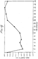
- Table 1 shows the pupil diameter of the left eye at different intervals following application of the test dose, as is represented graphically in Figure 19.
- Pupil Diameter (mm) Following Application of 2% Pilocarpine HCl Using a Laboratory Model Blister Crushing Device (Mean of 5 Rabbits) Measurement Timepoint Dose (0 min) +15 min +30 min +45 min + 1 hr +1.5 hr + 2 hr +2.5 hr + 3 hr +3.5 hr + 4 hr Mean 7.8 6.7 6.8 6.9 6.8 6.9 7.3 7.8 7.9 8.0 7.8
- Devices according to the invention can typically generate droplets with diameters of the order of 200 ⁇ m, enabling the delivery of multiple droplets in metered doses of very low volume, 5 ⁇ l being typical. However, smaller droplets can be desirable in some applications, as can larger droplets in others. A typical delivery velocity is 10 m/s, but other velocities may be appropriate in particular applications. Because of the manner in which the dose is delivered, this provides a significant benefit over traditional treatment techniques in which large doses of say 50 ⁇ l are used.
- Ophthalmic treatment fluids that may be used with the invention may be aqueous or non-aqueous liquids, optionally containing a therapeutic compound or compounds such as:
- the devices might comprise a single unit, as well as the modular systems illustrated in which the delivery mechanism and the treatment liquid source are provided separately, or at least independent of each other.
- Modular systems do of course enable a fluid or treatment liquid to be selected, and coupled to a delivery mechanism as desired. This enables the same delivery mechanism to be used for different treatments. Such a device for institutional use can provide for such selection to be at least partially automated.
Landscapes
- Health & Medical Sciences (AREA)
- Engineering & Computer Science (AREA)
- Biomedical Technology (AREA)
- Heart & Thoracic Surgery (AREA)
- Life Sciences & Earth Sciences (AREA)
- Animal Behavior & Ethology (AREA)
- General Health & Medical Sciences (AREA)
- Public Health (AREA)
- Veterinary Medicine (AREA)
- Mechanical Engineering (AREA)
- Ophthalmology & Optometry (AREA)
- Vascular Medicine (AREA)
- Bioinformatics & Cheminformatics (AREA)
- Dispersion Chemistry (AREA)
- Chemical & Material Sciences (AREA)
- Pulmonology (AREA)
- Anesthesiology (AREA)
- Hematology (AREA)
- Medical Preparation Storing Or Oral Administration Devices (AREA)
- Soil Working Implements (AREA)
- Laser Surgery Devices (AREA)
- Window Of Vehicle (AREA)
- Pharmaceuticals Containing Other Organic And Inorganic Compounds (AREA)
- Eye Examination Apparatus (AREA)
- Disintegrating Or Milling (AREA)
- Packages (AREA)
- Seasonings (AREA)
- Medicines That Contain Protein Lipid Enzymes And Other Medicines (AREA)
- General Preparation And Processing Of Foods (AREA)
Priority Applications (1)
| Application Number | Priority Date | Filing Date | Title |
|---|---|---|---|
| EP98102494A EP0845253B1 (en) | 1994-08-30 | 1995-08-30 | Package for fluid doses, ocular treatment device and use thereof |
Applications Claiming Priority (7)
| Application Number | Priority Date | Filing Date | Title |
|---|---|---|---|
| GB9417399 | 1994-08-30 | ||
| GB9417399A GB9417399D0 (en) | 1994-08-30 | 1994-08-30 | Ocular treatment device |
| GB9505472 | 1995-03-17 | ||
| GB9505474 | 1995-03-17 | ||
| GBGB9505472.2A GB9505472D0 (en) | 1995-03-17 | 1995-03-17 | Ocular treatment devices |
| GBGB9505474.8A GB9505474D0 (en) | 1995-03-17 | 1995-03-17 | Ocular treatment device |
| PCT/GB1995/002040 WO1996006581A1 (en) | 1994-08-30 | 1995-08-30 | Ocular treatment device |
Related Child Applications (1)
| Application Number | Title | Priority Date | Filing Date |
|---|---|---|---|
| EP98102494A Division EP0845253B1 (en) | 1994-08-30 | 1995-08-30 | Package for fluid doses, ocular treatment device and use thereof |
Publications (2)
| Publication Number | Publication Date |
|---|---|
| EP0778758A1 EP0778758A1 (en) | 1997-06-18 |
| EP0778758B1 true EP0778758B1 (en) | 1998-10-07 |
Family
ID=27267349
Family Applications (2)
| Application Number | Title | Priority Date | Filing Date |
|---|---|---|---|
| EP95930586A Expired - Lifetime EP0778758B1 (en) | 1994-08-30 | 1995-08-30 | Method of creating a directed stream of droplets |
| EP98102494A Expired - Lifetime EP0845253B1 (en) | 1994-08-30 | 1995-08-30 | Package for fluid doses, ocular treatment device and use thereof |
Family Applications After (1)
| Application Number | Title | Priority Date | Filing Date |
|---|---|---|---|
| EP98102494A Expired - Lifetime EP0845253B1 (en) | 1994-08-30 | 1995-08-30 | Package for fluid doses, ocular treatment device and use thereof |
Country Status (23)
| Country | Link |
|---|---|
| EP (2) | EP0778758B1 (es) |
| JP (2) | JPH10506028A (es) |
| KR (1) | KR100439006B1 (es) |
| CN (2) | CN1195466C (es) |
| AT (2) | ATE171858T1 (es) |
| AU (1) | AU703399B2 (es) |
| BG (1) | BG63143B1 (es) |
| BR (1) | BR9508672A (es) |
| CA (1) | CA2198892C (es) |
| CZ (1) | CZ294140B6 (es) |
| DE (2) | DE69531902T2 (es) |
| DK (2) | DK0778758T3 (es) |
| ES (2) | ES2125654T3 (es) |
| FI (1) | FI970706A (es) |
| GB (1) | GB2306902A (es) |
| HU (1) | HU220184B (es) |
| MX (1) | MX9701513A (es) |
| NO (1) | NO313224B1 (es) |
| NZ (1) | NZ292195A (es) |
| PL (2) | PL184709B1 (es) |
| PT (1) | PT845253E (es) |
| RO (1) | RO117294B1 (es) |
| WO (1) | WO1996006581A1 (es) |
Families Citing this family (51)
| Publication number | Priority date | Publication date | Assignee | Title |
|---|---|---|---|---|
| AU1201297A (en) * | 1995-12-21 | 1997-07-17 | Pharmacia & Upjohn Ab | Ophthalmic treatment |
| AUPN976496A0 (en) * | 1996-05-10 | 1996-05-30 | Glaxo Wellcome Australia Ltd | Unit dose dispensing device |
| US5829435A (en) * | 1997-02-24 | 1998-11-03 | Aradigm Corporation | Prefilter for prevention of clogging of a nozzle in the generation of an aerosol and prevention of administration of undesirable particles |
| US6423040B1 (en) | 1997-06-02 | 2002-07-23 | Pharmacia Ab | Eye fluid applicator |
| CA2333978A1 (en) * | 1998-06-02 | 1999-12-09 | Bausch & Lomb Incorporated | Limited-dose dispenser for ophthalmic solutions |
| US6070575A (en) * | 1998-11-16 | 2000-06-06 | Aradigm Corporation | Aerosol-forming porous membrane with certain pore structure |
| US6730066B1 (en) | 1999-08-03 | 2004-05-04 | Pharmacia Ab | Liquid delivery container |
| CZ2002409A3 (cs) * | 1999-08-03 | 2002-09-11 | Pharmacia Ab | Přetlaková nádoba pro uchovávání a vypouštění kapaliny, způsob výroby nádoby a zařízení pro vypouštění kapaliny z nádoby |
| AR029768A1 (es) * | 1999-10-18 | 2003-07-16 | Novartis Ag | Paquete de plastico para un producto farmaceutico y metodo para fabricar y esterilizar un paquete farmaceutico |
| AU1842400A (en) | 1999-12-06 | 2001-06-12 | Robert A. Laibovitz | Apparatus and method for delivery of small volumes of liquid |
| US7171965B2 (en) | 2000-02-01 | 2007-02-06 | Valois S.A.S. | Breath actuated dry powder inhaler and tape dose strip |
| PE20020578A1 (es) | 2000-10-10 | 2002-08-14 | Upjohn Co | Una composicion de antibiotico topico para el tratamiento de infecciones oculares |
| US6758837B2 (en) | 2001-02-08 | 2004-07-06 | Pharmacia Ab | Liquid delivery device and method of use thereof |
| JP2007534384A (ja) * | 2004-04-23 | 2007-11-29 | ミスティック ファーマシューティカルズ, インコーポレイテッド | 複数の単位用量の薬物送達システム |
| TWI428271B (zh) * | 2004-06-09 | 2014-03-01 | Smithkline Beecham Corp | 生產藥物之裝置及方法 |
| US8101244B2 (en) | 2004-06-09 | 2012-01-24 | Smithkline Beecham Corporation | Apparatus and method for producing or processing a product or sample |
| JP5137956B2 (ja) * | 2006-09-29 | 2013-02-06 | テイアサイエンス・インコーポレーテツド | 流体ジェットを用いてマイボーム腺機能不全を治療する方法および装置 |
| US20090092574A1 (en) | 2006-12-29 | 2009-04-09 | Scott Richard W | Ophthalmic And Otic Compositions Of Facially Amphiphilic Polymers And Oligomers And Uses Thereof |
| CN101715428B (zh) * | 2007-05-16 | 2016-08-24 | 神秘制药公司 | 用于输送药物组成物的剂型和包括该剂型的剂量带 |
| AT505246B8 (de) * | 2007-06-01 | 2009-06-15 | Croma Pharma Gmbh | Container für eine mehrzahl von einzeldosen sowie applikator für derartige container |
| EP2077132A1 (en) * | 2008-01-02 | 2009-07-08 | Boehringer Ingelheim Pharma GmbH & Co. KG | Dispensing device, storage device and method for dispensing a formulation |
| CZ303279B6 (cs) * | 2009-02-06 | 2012-07-11 | Stodulka@Pavel | Ocní aplikátor k injekcnímu vpravování substance do tkáne oka |
| WO2010053487A1 (en) | 2008-11-07 | 2010-05-14 | Cydex Pharmaceuticals, Inc. | Composition containing sulfoalkyl ether cyclodextrin and latanoprost |
| EP2662472B1 (de) | 2009-03-31 | 2019-02-27 | Boehringer Ingelheim International Gmbh | Verfahren zur Beschichtung einer Oberfläche eines Bauteils |
| EP3508239B1 (de) | 2009-05-18 | 2020-12-23 | Boehringer Ingelheim International GmbH | Adapter, inhalationseinrichtung und zerstäuber |
| BRPI1011194A2 (pt) * | 2009-05-21 | 2016-12-27 | Microdose Therapeutx Inc | sistema de receptáculo rotativo para inalador de pó seco |
| US8985101B2 (en) | 2009-05-21 | 2015-03-24 | Microdose Therapeutx, Inc. | Method and device for clamping a blister within a dry powder inhaler |
| NZ599295A (en) | 2009-11-25 | 2014-06-27 | Boehringer Ingelheim Int | Nebulizer |
| EP2504051B1 (en) | 2009-11-25 | 2019-09-04 | Boehringer Ingelheim International GmbH | Nebulizer |
| US10016568B2 (en) | 2009-11-25 | 2018-07-10 | Boehringer Ingelheim International Gmbh | Nebulizer |
| EP2585151B1 (en) | 2010-06-24 | 2018-04-04 | Boehringer Ingelheim International GmbH | Nebulizer |
| EA201390120A3 (ru) | 2010-07-15 | 2013-09-30 | Коринтиан Офтэлмик, Инк. | Доставка офтальмологических лекарственных средств |
| JP2013531548A (ja) * | 2010-07-15 | 2013-08-08 | コリンシアン オフサルミック,インコーポレイティド | 遠隔治療及び遠隔モニタリングを実施する方法及びシステム |
| US10154923B2 (en) | 2010-07-15 | 2018-12-18 | Eyenovia, Inc. | Drop generating device |
| EP2694220B1 (de) | 2011-04-01 | 2020-05-06 | Boehringer Ingelheim International GmbH | Medizinisches gerät mit behälter |
| US9827384B2 (en) | 2011-05-23 | 2017-11-28 | Boehringer Ingelheim International Gmbh | Nebulizer |
| WO2013028934A1 (en) * | 2011-08-23 | 2013-02-28 | Temptu , Inc. | Ultrasonic spraying device/air-assisted ultrasonic spraying device with advancing cartridge piston |
| CN104487028A (zh) | 2011-12-12 | 2015-04-01 | 艾诺维亚股份有限公司 | 高模量聚合物喷射器机构、喷射器装置及其使用方法 |
| DE102012002940A1 (de) * | 2012-02-16 | 2013-08-22 | Udo Tartler | Vorrichtung zum Versprühen von Flüssigkeit insbesondere auf eine Oberfläche |
| WO2013152894A1 (de) | 2012-04-13 | 2013-10-17 | Boehringer Ingelheim International Gmbh | Zerstäuber mit kodiermitteln |
| CN102908226B (zh) * | 2012-11-12 | 2014-07-09 | 杨勋 | 稳固型自疏通青光眼钉 |
| EP2835146B1 (en) | 2013-08-09 | 2020-09-30 | Boehringer Ingelheim International GmbH | Nebulizer |
| US9744313B2 (en) | 2013-08-09 | 2017-08-29 | Boehringer Ingelheim International Gmbh | Nebulizer |
| US20160235930A1 (en) | 2013-10-01 | 2016-08-18 | Novartis Ag | Blister track inhaler device having a separate end path and methods of use thereof |
| US10195374B2 (en) | 2014-05-07 | 2019-02-05 | Boehringer Ingelheim International Gmbh | Container, nebulizer and use |
| WO2015169430A1 (en) | 2014-05-07 | 2015-11-12 | Boehringer Ingelheim International Gmbh | Nebulizer |
| US10716906B2 (en) | 2014-05-07 | 2020-07-21 | Boehringer Ingelheim International Gmbh | Nebulizer and container |
| CA3066408A1 (en) | 2017-06-10 | 2018-12-13 | Eyenovia, Inc. | Methods and devices for handling a fluid and delivering the fluid to the eye |
| CA3131264A1 (en) * | 2019-03-04 | 2020-09-10 | Eyenovia, Inc. | Methods and devices for delivering pilocarpine to the eye as a micro-dose stream of droplets |
| CN113576746B (zh) * | 2021-08-02 | 2024-05-03 | 中南大学湘雅二医院 | 一种滴眼药装置 |
| CN113856027B (zh) * | 2021-11-09 | 2023-08-01 | 南京傲晨智能化建设工程有限公司 | 一种皮肤科防交叉感染的涂药装置 |
Family Cites Families (13)
| Publication number | Priority date | Publication date | Assignee | Title |
|---|---|---|---|---|
| FR660550A (fr) * | 1927-10-22 | 1929-07-12 | Perfectionnements aux jouets musicaux | |
| AU414085B2 (en) * | 1967-01-31 | 1971-06-14 | M. S. F. R. C. S. F. RA. C. S. and IAN HOWARD MUDIE ROEGER NOEL JAMES BONNIN | An improved dispensing container |
| GB1518998A (en) * | 1975-08-28 | 1978-07-26 | Gillette Co | Packaging flowable materials |
| DE2717578C2 (de) * | 1977-04-20 | 1979-07-05 | Paul Pleiger Maschinenfabrik, 5810 Witten | Pumpe oder Verdichter |
| US4338936A (en) * | 1980-10-27 | 1982-07-13 | Byron Nelson | Device and method for delivering solid medication to an eye |
| US4871091A (en) * | 1988-09-29 | 1989-10-03 | Mason-Keller Corporation | Disposable package for liquids |
| GB8909891D0 (en) * | 1989-04-28 | 1989-06-14 | Riker Laboratories Inc | Device |
| GB9004781D0 (en) * | 1990-03-02 | 1990-04-25 | Glaxo Group Ltd | Device |
| US5094594A (en) * | 1990-04-23 | 1992-03-10 | Genomyx, Incorporated | Piezoelectric pumping device |
| GB9109064D0 (en) * | 1991-04-26 | 1991-06-12 | Dunne Miller Weston Ltd | Dispensing device |
| WO1993015972A1 (en) * | 1992-02-13 | 1993-08-19 | Tecnilens S.R.L. | Multiple package for pharmaceutical products |
| US5368582A (en) * | 1992-08-10 | 1994-11-29 | The Schepens Eye Research Institute | Method and apparatus for introducing fluid material into an eye |
| US5349947A (en) * | 1993-07-15 | 1994-09-27 | Newhouse Michael T | Dry powder inhaler and process that explosively discharges a dose of powder and gas from a soft plastic pillow |
-
1995
- 1995-08-30 DK DK95930586T patent/DK0778758T3/da active
- 1995-08-30 DE DE69531902T patent/DE69531902T2/de not_active Expired - Fee Related
- 1995-08-30 MX MX9701513A patent/MX9701513A/es unknown
- 1995-08-30 CA CA002198892A patent/CA2198892C/en not_active Expired - Fee Related
- 1995-08-30 DE DE69505266T patent/DE69505266T2/de not_active Expired - Fee Related
- 1995-08-30 EP EP95930586A patent/EP0778758B1/en not_active Expired - Lifetime
- 1995-08-30 AU AU33914/95A patent/AU703399B2/en not_active Ceased
- 1995-08-30 PL PL95345881A patent/PL184709B1/pl not_active IP Right Cessation
- 1995-08-30 NZ NZ292195A patent/NZ292195A/en unknown
- 1995-08-30 AT AT95930586T patent/ATE171858T1/de not_active IP Right Cessation
- 1995-08-30 DK DK98102494T patent/DK0845253T3/da active
- 1995-08-30 RO RO97-00392A patent/RO117294B1/ro unknown
- 1995-08-30 GB GB9704403A patent/GB2306902A/en not_active Withdrawn
- 1995-08-30 HU HU9701993A patent/HU220184B/hu unknown
- 1995-08-30 CN CNB951948512A patent/CN1195466C/zh not_active Expired - Fee Related
- 1995-08-30 CN CNA2005100059576A patent/CN1669542A/zh active Pending
- 1995-08-30 AT AT98102494T patent/ATE251433T1/de not_active IP Right Cessation
- 1995-08-30 CZ CZ1997596A patent/CZ294140B6/cs not_active IP Right Cessation
- 1995-08-30 JP JP8508562A patent/JPH10506028A/ja active Pending
- 1995-08-30 KR KR1019970701439A patent/KR100439006B1/ko not_active IP Right Cessation
- 1995-08-30 EP EP98102494A patent/EP0845253B1/en not_active Expired - Lifetime
- 1995-08-30 PL PL95318935A patent/PL184059B1/pl not_active IP Right Cessation
- 1995-08-30 WO PCT/GB1995/002040 patent/WO1996006581A1/en active IP Right Grant
- 1995-08-30 ES ES95930586T patent/ES2125654T3/es not_active Expired - Lifetime
- 1995-08-30 PT PT98102494T patent/PT845253E/pt unknown
- 1995-08-30 BR BR9508672A patent/BR9508672A/pt not_active IP Right Cessation
- 1995-08-30 ES ES98102494T patent/ES2208980T3/es not_active Expired - Lifetime
-
1997
- 1997-02-19 FI FI970706A patent/FI970706A/fi unknown
- 1997-02-27 NO NO19970874A patent/NO313224B1/no unknown
- 1997-03-28 BG BG101365A patent/BG63143B1/bg unknown
-
2005
- 2005-06-27 JP JP2005186671A patent/JP2005324051A/ja active Pending
Also Published As
Similar Documents
| Publication | Publication Date | Title |
|---|---|---|
| EP0778758B1 (en) | Method of creating a directed stream of droplets | |
| US6726665B1 (en) | Ocular treatment device | |
| MXPA97001513A (es) | Dispositivo para tratamiento ocular | |
| US8683995B2 (en) | Dose dispensing containers | |
| AU781452B2 (en) | Pore structures for reduced pressure aerosolization | |
| US6732954B2 (en) | Pore structures for reduced pressure aerosolization | |
| CA2538944A1 (en) | Ocular treatment device | |
| RU2207885C2 (ru) | Способ подачи небольшого объема лечебного раствора к целевому месту |
Legal Events
| Date | Code | Title | Description |
|---|---|---|---|
| PUAI | Public reference made under article 153(3) epc to a published international application that has entered the european phase |
Free format text: ORIGINAL CODE: 0009012 |
|
| 17P | Request for examination filed |
Effective date: 19970227 |
|
| AK | Designated contracting states |
Kind code of ref document: A1 Designated state(s): AT BE CH DE DK ES FR GB GR IE IT LI LU MC NL PT SE |
|
| GRAG | Despatch of communication of intention to grant |
Free format text: ORIGINAL CODE: EPIDOS AGRA |
|
| 17Q | First examination report despatched |
Effective date: 19970912 |
|
| GRAG | Despatch of communication of intention to grant |
Free format text: ORIGINAL CODE: EPIDOS AGRA |
|
| GRAH | Despatch of communication of intention to grant a patent |
Free format text: ORIGINAL CODE: EPIDOS IGRA |
|
| RAP1 | Party data changed (applicant data changed or rights of an application transferred) |
Owner name: PHARMACIA & UPJOHN AKTIEBOLAG |
|
| GRAH | Despatch of communication of intention to grant a patent |
Free format text: ORIGINAL CODE: EPIDOS IGRA |
|
| GRAA | (expected) grant |
Free format text: ORIGINAL CODE: 0009210 |
|
| AK | Designated contracting states |
Kind code of ref document: B1 Designated state(s): AT BE CH DE DK ES FR GB GR IE IT LI LU MC NL PT SE |
|
| REF | Corresponds to: |
Ref document number: 171858 Country of ref document: AT Date of ref document: 19981015 Kind code of ref document: T |
|
| REG | Reference to a national code |
Ref country code: CH Ref legal event code: EP |
|
| REF | Corresponds to: |
Ref document number: 69505266 Country of ref document: DE Date of ref document: 19981112 |
|
| REG | Reference to a national code |
Ref country code: IE Ref legal event code: FG4D |
|
| REG | Reference to a national code |
Ref country code: CH Ref legal event code: NV Representative=s name: DIETLIN & CIE S.A. |
|
| ET | Fr: translation filed | ||
| REG | Reference to a national code |
Ref country code: ES Ref legal event code: FG2A Ref document number: 2125654 Country of ref document: ES Kind code of ref document: T3 |
|
| REG | Reference to a national code |
Ref country code: PT Ref legal event code: SC4A Free format text: AVAILABILITY OF NATIONAL TRANSLATION Effective date: 19990106 |
|
| REG | Reference to a national code |
Ref country code: DK Ref legal event code: T3 |
|
| PLBE | No opposition filed within time limit |
Free format text: ORIGINAL CODE: 0009261 |
|
| STAA | Information on the status of an ep patent application or granted ep patent |
Free format text: STATUS: NO OPPOSITION FILED WITHIN TIME LIMIT |
|
| 26N | No opposition filed | ||
| REG | Reference to a national code |
Ref country code: GB Ref legal event code: IF02 |
|
| PGFP | Annual fee paid to national office [announced via postgrant information from national office to epo] |
Ref country code: PT Payment date: 20070628 Year of fee payment: 13 |
|
| PGFP | Annual fee paid to national office [announced via postgrant information from national office to epo] |
Ref country code: MC Payment date: 20070704 Year of fee payment: 13 |
|
| PGFP | Annual fee paid to national office [announced via postgrant information from national office to epo] |
Ref country code: LU Payment date: 20070705 Year of fee payment: 13 |
|
| PGFP | Annual fee paid to national office [announced via postgrant information from national office to epo] |
Ref country code: DK Payment date: 20070710 Year of fee payment: 13 |
|
| PGFP | Annual fee paid to national office [announced via postgrant information from national office to epo] |
Ref country code: IE Payment date: 20070713 Year of fee payment: 13 |
|
| PGFP | Annual fee paid to national office [announced via postgrant information from national office to epo] |
Ref country code: ES Payment date: 20070806 Year of fee payment: 13 |
|
| PGFP | Annual fee paid to national office [announced via postgrant information from national office to epo] |
Ref country code: DE Payment date: 20070831 Year of fee payment: 13 |
|
| PGFP | Annual fee paid to national office [announced via postgrant information from national office to epo] |
Ref country code: CH Payment date: 20070709 Year of fee payment: 13 Ref country code: AT Payment date: 20070704 Year of fee payment: 13 |
|
| PGFP | Annual fee paid to national office [announced via postgrant information from national office to epo] |
Ref country code: GB Payment date: 20070705 Year of fee payment: 13 |
|
| PGFP | Annual fee paid to national office [announced via postgrant information from national office to epo] |
Ref country code: SE Payment date: 20070802 Year of fee payment: 13 Ref country code: NL Payment date: 20070710 Year of fee payment: 13 Ref country code: IT Payment date: 20070814 Year of fee payment: 13 Ref country code: BE Payment date: 20070830 Year of fee payment: 13 |
|
| PGFP | Annual fee paid to national office [announced via postgrant information from national office to epo] |
Ref country code: FR Payment date: 20070803 Year of fee payment: 13 |
|
| PGFP | Annual fee paid to national office [announced via postgrant information from national office to epo] |
Ref country code: GR Payment date: 20070702 Year of fee payment: 13 |
|
| REG | Reference to a national code |
Ref country code: PT Ref legal event code: MM4A Free format text: LAPSE DUE TO NON-PAYMENT OF FEES Effective date: 20090302 |
|
| REG | Reference to a national code |
Ref country code: DK Ref legal event code: EBP |
|
| PG25 | Lapsed in a contracting state [announced via postgrant information from national office to epo] |
Ref country code: MC Free format text: LAPSE BECAUSE OF NON-PAYMENT OF DUE FEES Effective date: 20080831 |
|
| REG | Reference to a national code |
Ref country code: CH Ref legal event code: PL |
|
| EUG | Se: european patent has lapsed | ||
| GBPC | Gb: european patent ceased through non-payment of renewal fee |
Effective date: 20080830 |
|
| PG25 | Lapsed in a contracting state [announced via postgrant information from national office to epo] |
Ref country code: AT Free format text: LAPSE BECAUSE OF NON-PAYMENT OF DUE FEES Effective date: 20080830 |
|
| NLV4 | Nl: lapsed or anulled due to non-payment of the annual fee |
Effective date: 20090301 |
|
| PG25 | Lapsed in a contracting state [announced via postgrant information from national office to epo] |
Ref country code: PT Free format text: LAPSE BECAUSE OF NON-PAYMENT OF DUE FEES Effective date: 20090302 Ref country code: NL Free format text: LAPSE BECAUSE OF NON-PAYMENT OF DUE FEES Effective date: 20090301 |
|
| REG | Reference to a national code |
Ref country code: FR Ref legal event code: ST Effective date: 20090430 |
|
| REG | Reference to a national code |
Ref country code: IE Ref legal event code: MM4A |
|
| PG25 | Lapsed in a contracting state [announced via postgrant information from national office to epo] |
Ref country code: LI Free format text: LAPSE BECAUSE OF NON-PAYMENT OF DUE FEES Effective date: 20080831 Ref country code: GR Free format text: LAPSE BECAUSE OF NON-PAYMENT OF DUE FEES Effective date: 20090304 Ref country code: CH Free format text: LAPSE BECAUSE OF NON-PAYMENT OF DUE FEES Effective date: 20080831 |
|
| PG25 | Lapsed in a contracting state [announced via postgrant information from national office to epo] |
Ref country code: IE Free format text: LAPSE BECAUSE OF NON-PAYMENT OF DUE FEES Effective date: 20080901 Ref country code: DK Free format text: LAPSE BECAUSE OF NON-PAYMENT OF DUE FEES Effective date: 20080831 Ref country code: BE Free format text: LAPSE BECAUSE OF NON-PAYMENT OF DUE FEES Effective date: 20080831 |
|
| PG25 | Lapsed in a contracting state [announced via postgrant information from national office to epo] |
Ref country code: IT Free format text: LAPSE BECAUSE OF NON-PAYMENT OF DUE FEES Effective date: 20080830 Ref country code: FR Free format text: LAPSE BECAUSE OF NON-PAYMENT OF DUE FEES Effective date: 20080901 Ref country code: DE Free format text: LAPSE BECAUSE OF NON-PAYMENT OF DUE FEES Effective date: 20090303 |
|
| REG | Reference to a national code |
Ref country code: ES Ref legal event code: FD2A Effective date: 20080901 |
|
| PG25 | Lapsed in a contracting state [announced via postgrant information from national office to epo] |
Ref country code: GB Free format text: LAPSE BECAUSE OF NON-PAYMENT OF DUE FEES Effective date: 20080830 |
|
| PG25 | Lapsed in a contracting state [announced via postgrant information from national office to epo] |
Ref country code: ES Free format text: LAPSE BECAUSE OF NON-PAYMENT OF DUE FEES Effective date: 20080901 |
|
| PG25 | Lapsed in a contracting state [announced via postgrant information from national office to epo] |
Ref country code: LU Free format text: LAPSE BECAUSE OF NON-PAYMENT OF DUE FEES Effective date: 20080830 |
|
| PG25 | Lapsed in a contracting state [announced via postgrant information from national office to epo] |
Ref country code: SE Free format text: LAPSE BECAUSE OF NON-PAYMENT OF DUE FEES Effective date: 20080831 |