EP0773449B1 - Magnetfeldfühler - Google Patents
Magnetfeldfühler Download PDFInfo
- Publication number
- EP0773449B1 EP0773449B1 EP96116894A EP96116894A EP0773449B1 EP 0773449 B1 EP0773449 B1 EP 0773449B1 EP 96116894 A EP96116894 A EP 96116894A EP 96116894 A EP96116894 A EP 96116894A EP 0773449 B1 EP0773449 B1 EP 0773449B1
- Authority
- EP
- European Patent Office
- Prior art keywords
- magnetic field
- magnetic
- magneto
- sensor
- field sensor
- Prior art date
- Legal status (The legal status is an assumption and is not a legal conclusion. Google has not performed a legal analysis and makes no representation as to the accuracy of the status listed.)
- Expired - Lifetime
Links
Images


Classifications
-
- G—PHYSICS
- G01—MEASURING; TESTING
- G01R—MEASURING ELECTRIC VARIABLES; MEASURING MAGNETIC VARIABLES
- G01R33/00—Arrangements or instruments for measuring magnetic variables
- G01R33/02—Measuring direction or magnitude of magnetic fields or magnetic flux
- G01R33/022—Measuring gradient
Definitions
- the present invention relates to a magnetic field sensor, and more particularly to a magnetic field sensor which can detect gradient magnetic fields and which can be used in various technical fields.
- the magnetic field sensor of the present invention can be used as a magnetic sensor head for a rotary encoder used for sophisticated arm control of an industrial robot in which the magnetic sensor head is combined with a high density ring magnet, as a sensitive magnetic sensor head for magnetic inspection, as a magnetic sensor head for detecting the image of magnetic domains of a magnetic material, as a magnetic sensor head for a high density magnetic disc of a computer, as a magnetic sensor head for a rotary encoder used for controlling the rotation of a storage disc of a computer in which the magnetic sensor head is combined with a ring magnet, as a magnetic sensor for detecting a magnetic field of an automobile, as a magnetic direction sensor, as any one of various types of magnetic sensors for current detection, or as a like device.
- magnetic sensor heads are a key technology in the modern computerized society which has progressed more and more.
- Various magnetic sensor heads such as a magnetic sensor head for a rotary encoder used in an industrial robot, a sensitive magnetic sensor head for magnetic inspection, a magnetic sensor head for detecting magnetic domains of a magnetic material, a magnetic sensor head for a high density magnetic disc, and a magnetic sensor head for a rotary encoder used for controlling the rotation of a storage disc are all required to detect weak signal magnetic fields, which have recently become more and more weakened. Also, such magnetic sensor heads are required to detect only a signal magnetic field in a disturbance field or background field stronger than the signal magnetic field, such as the terrestrial field.
- a magnetic field sensor which can cancel disturbance fields, which are spatially uniform as compared with a signal magnetic field, so as to detect, as a differential magnetic field, only the signal magnetic field which is spatially gradient.
- MI magneto-impedance
- Hall elements nor magneto resistance (MR) elements have sufficient sensitivity.
- flux gate sensors have high sensitivity for uniform magnetic fields, they are not satisfactory in terms of their sizes and response speeds.
- the MI element proposed by the present inventors has a high resolution of 7,958.10 -5 Am -1 (10 -6 Oe) in detecting alternating magnetic fields, a very high sensitivity, and a high response speed which allows detection of magnetic fields from DC (0 Hz) to a few MHz, despite its compact size of about 1 mm long.
- the power consumption of the entire sensor circuit is not greater than about 40 mW, it is easy to assemble a sensor array using these MI elements. None of various types of conventional magnetic sensors possesses these excellent characteristics.
- the strengths of magnetic fields to be measured have been decreased and the frequencies of magnetic fields to be measured have been increased, especially in the fields of computers, information equipment, mechatoronics, power electronics, medical electronics, industrial measurement, and environmental measurement.
- the strengths of magnetic fields are on the order of milli Oe, and the frequencies of the magnetic fields range from a few tens of kHz to a few hundreds of kHz. Therefore, conventional Hall elements, MR elements, and the like cannot be used due to their insufficient sensitivities. Conventional flux gate sensors cannot be used due to their insufficient response speeds and large head lengths.
- a method for detecting a gradient magnetic field while canceling the background magnetic field has been proposed in relation to a gradio meter of SQUID (superconductive quantum interference device).
- SQUID superconductive quantum interference device
- MI elements which are new high performance micro magnetic field sensors.
- a magnetic field sensor according to the preamble of claim 1 is known from US 3 065 413.
- An object of the present invention is to solve the above-mentioned problems in the conventional magnetic field sensors and to provide a magnetic field sensor for gradient field detection (gradient type magnetic field sensor) which can cancel relatively uniform disturbance magnetic fields (background magnetic fields), such as the terrestrial field, thereby making it possible to detect only a signal magnetic field (gradient field) which is considerably localized spatially.
- gradient field detection gradient type magnetic field sensor
- the detection means is composed of a self-oscillation type electronic circuit.
- the said self-oscillation type electronic circuit preferably comprises a multivibrator high frequency oscillator which has a pair of transistors and performs amplitude modulation.
- the sensor heads are made of an amorphous wire or a thin film.
- the sensor heads is made of an amorphous wire
- the bias magnetic fields are generated by supplying direct currents to coils wound around the magneto-impedance elements.
- the self-oscillation type electronic circuit comprises a multivibrator high frequency oscillator which has a pair of transistors and performs amplitude modulation, it becomes possible to obtain a magnetic field sensor which is highly sensitive and operates stably.
- FIG. 1 shows the overall structure of a magnetic field sensor according to an embodiment of the present invention
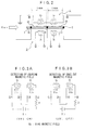
- FIG. 2 shows the structure of the head portion of the magnetic field sensor
- FIG. 3A shows the interconnection between two bias coils of the magnetic field sensor for detection of uniform magnetic fields
- FIG. 3B shows the interconnection between the two bias coils of the magnetic field sensor for detection of gradient magnetic fields
- FIG. 4 shows the interconnection between two feedback coils of the magnetic field sensor.
- the magnetic field sensor includes a pair of sensor heads A and a self-oscillation type electronic circuit B.
- the pair of sensor heads A includes a common amorphous wire 1 (magnetostriction: 0, diameter: 30 ⁇ m, length: about 3 mm) serving as a magnetic member.
- Soldering electrode terminals 2 (2a, 2b and 2c) are provided at three different locations on the amorphous wire 1.
- Two portions, 1A and 1B, of the amorphous wire 1 between the electrode terminals 2 serve as the pair of sensor heads A.
- the amorphous wire 1 is made of, for example, an FeCoSiB material.
- a tensile stress of 2 kg/mm 2 is applied to the FeCoSiB material during an annealing process in which the FeCoSiB material is heated at 475°C for one minute and is then cooled to room temperature.
- two bias coils 3 (3a and 3b) and two feedback coils 4 (4a and 4b) are wound around the pair of sensor heads A formed of a magnetic member.
- the bias coils 3a and 3b are connected to a DC power supply Eb through a resistor R (100 ⁇ ) such that the bias coils 3a and 3b generate bias magnetic fields oriented in the same direction, as shown in FIG. 3A.
- the bias coils 3a and 3b are connected to the DC power supply Eb through the resistor R (100 ⁇ ) such that the bias coils 3a and 3b generate bias magnetic fields oriented in opposite directions, as shown in FIG. 3B.
- the feedback coils 4a and 4b are connected to the output of the self-oscillation type electronic circuit B through a feedback resistor 62 (see FIG. 1) such that the feedback coils 4a and 4b generate magnetic fields oriented in the same direction.
- the self-oscillation type electronic circuit B consists of a multivibrator oscillation circuit 10, a differential amplifier 30, a detection circuit 40, and an output-stage amplifier 50.
- the multivibrator oscillation circuit 10 consists of a resistor 17 (R: 1O ⁇ ), a DC power supply 18 (E), inductances 11 and 19 [chip elements (L chip ): 0.12 ⁇ H] resistors 12 and 20 ( R b1 and R b2 20 k ⁇ ), capacitors 13 and 21 (C b1 and C b2 : 220 pF), transistors 14 and 22 (Tr1 and Tr2: 2SC1162), resistors 15 and 23 (R: 30 k ⁇ ), and resistors 16 and 24 (R 0 : 3 ⁇ ).
- the multivibrator oscillation circuit 10 is connected to the differential amplifier 30.
- the differential amplifier 30 consists of resistors 31 and 32 (R 1 and R 2 : 510 ⁇ ), a resistor 33 (R 4 : 1 k ⁇ ), an operational amplifier 34 (OP1: LM6361N) and a resistor 35 (R 3 : 1 k ⁇ ), and is connected to the detection circuit 40.
- the detection circuit 40 consists of a Schottky barrierdiode 41 (D: 1SS97), and an RC circuit consisting of a resistor 42 (R 5 : 300 k ⁇ ) and a capacitor 43 (C 1 : 2200 pF).
- the detection circuit 40 is connected to the output-stage amplifier 50.
- the output-stage amplifier 50 consists of resistors 51, 52 and 53 (R 6 , R 7 and R 12 : 10 k ⁇ ), a variable resistor 54 (R 13 : max. 5 k ⁇ ), a resistor 55 (R 9 : 100 k ⁇ ), an operational amplifier 56 (OP2: LM356N), a resistor 57 (R 8 : 100 k ⁇ ), a resistor 58 (R 10 : 1 k ⁇ ),an operational amplifier 59 (OP3: LM356N), and a resistor 60 (R 11 : 100 k ⁇ ).
- Numeral 61 denotes the above-mentioned switch SW1
- numeral 62 denotes the above-mentioned feedback resistor (Rf: max. 3k ⁇ ).
- the feedback resistor 62 is grounded through the feedback coils 4a and 4b serially connected to the feedback resistor 62.
- Numeral 63 denotes an output terminal.
- the multivibrator oscillation circuit 10 oscillates at about 20 MHz, and the oscillation voltage thereof undergoes amplitude modulation due to an externally applied magnetic field Hex.
- the modulated oscillation voltage is supplied, through the differential amplifier 30, to the detection circuit 40 having the above-mentioned Schottky barrier diode 41 and the RC circuit consisting of the resistor 42 and the capacitor 43, in which the modulated oscillation voltage is detected.
- the detection voltage output from the detection circuit 40 is amplified by the operational amplifiers 56 and 59 to a sufficient level, so that an output voltage Eout is obtained from the output terminal 63.
- the output voltage Eout is proportional to the externally applied magnetic field Hex.
- the magnetic field sensor functions as a linear magnetic field sensor.
- the output voltage Eout is proportional to the difference in the magnetic field strength between the two portions 1A and 1B of the amorphous wire 1 serving as the sensor heads A.
- FIG. 5 is a characteristic chart (characteristic chart for detection of uniform magnetic fields) of the magnetic field sensor of the present invention, which shows the relationship between an externally applied magnetic field and the output voltage.
- This characteristic chart shows the characteristic when the magnitude of a sinusoidal magnetic field (frequency: 1 kHz) is varied from -7,958 ⁇ 10 1 Am -1 to 7,958.10 1 Am -1 (-1 Oe (oersted) to +1 Oe).
- the magnetic field sensor of the present invention exhibits a nonlinearity of 0.2% or less at the full scale, so that it has an excellent linearity.
- the minimum detectable strength of the magnetic field is about 7,958.10 -5 Am -1 (10 -6 Oe).
- FIG. 6 is a characteristic chart showing the frequency characteristic of the magnetic field sensor of the present invention.
- This chart shows the detection characteristic (frequency characteristic) when the frequency f of a sinusoidal magnetic field (amplitude: 1,5916 Am -1 (0.02 Oe)) is varied.
- the horizontal axis represents the frequency (kHz) of the sinusoidal magnetic field while the vertical axis represents the variation ⁇ Eout (dB) of the output voltage of the sensor.
- FIGS. 7A and 7B show the results of experiments in which the surface magnetic field of a ring magnet of a rotary encoder for robot control was detected by the magnetic field sensor of the present invention operated in a differential mode.
- FIG. 7A shows the case where the ring magnet had a diameter of 19 mm and 1000 magnetic poles (the pitch of magnetic poles: 60 ⁇ m)
- FIG. 7B shows the case where the ring magnet had a diameter of 19 mm and 2000 magnetic poles (the pitch of magnetic poles : 30 ⁇ m).
- the horizontal axis represents the recurrence of N and S magnetic poles, while the vertical axis represents the sensor output (7,958.10 -2 Am -1 (mOe)).
- the magnetic field sensor When the magnetic field sensor was used in a differential mode, the negative feedback was not used. Since the magnetic field sensor was operated in the differential mode, the sensor was not at all affected by the terrestrial field. The influence of the rotor magnetic field of a magnet motor for driving an encoder decreased by about 75% through the operation in the differential mode.
- the sensor heads are made of an amorphous wire
- an amorphous thin film may be used instead of the amorphous wire.
Landscapes
- Physics & Mathematics (AREA)
- Condensed Matter Physics & Semiconductors (AREA)
- General Physics & Mathematics (AREA)
- Measuring Magnetic Variables (AREA)
Claims (7)
- Magnetfeldfühler umfassend ein Paar Fühlerköpfe (A) mit einem Magnetelement (1); Magnetfeld-Erzeugungsmittel (Eb, R, 3a, 3b) zum Anlegen eines Magnetfeldes an das Paar Fühlerköpfe (A); und Erfassungsmittel (B) zum Erfassen eines Differentialwertes eines räumlich ansteigenden Magnetfeldes (Hex),
dadurch gekennzeichnet, daß
jeder der Fühlerköpfe (A) aus einem Magnetimpedanz-(MI)-Element (1A, 1B) gefertigt ist, wobei die MI-Elemente in derselben Richtung verlaufen und entweder aus amorphem Draht oder amorphem Dünnfilm hergestellt sind;
wobei die Magnetfeld-Erzeugungseinrichtung (Eb, R, 3a, 3b) geeignet ist, an jedes der Magnetimpedanzelemente (1A, 1B) ein Magnetfeld mit Gleichstromvormagnetisierung in einer Richtung parallel zu den Magnetimpedanzelementen (1A, 1B) und einander gegenüberliegend anzulegen; und
wobei die Erfassungseinrichtung (B) mit den Magnetimpedanzelementen (1A, 1B) elektrisch verbunden und geeignet ist, einen Differentialwert eines räumlich ansteigenden Magnetfeldes (Hex) auf Basis der Impedanzen des Paars von Magnetimpedanzelementen (1A, 1B) zu erfassen. - Magnetfeldfühler gemäß Anspruch 1, wobei die Erfassungseinrichtung (B) aus einer elektronischen Schaltung des Typs mit selbst erregter Schwingung besteht.
- Magnetfeldfühler gemäß Anspruch 2, wobei die elektronische Schaltung des Typs mit selbst erregter Schwingung einen Multivibrator-Hochfrequenzoszillator (10) umfaßt, der ein Paar Transistoren (14, 22) aufweist und die Amplitudenmodulation durchführt.
- Magnetfeldfühler gemäß Anspruch 1, wobei der amorphe Draht (1) mit drei Elektroden (2a, 2b, 2c) versehen ist, die an unterschiedlichen Längslageorten ausgebildet sind, und zwei Abschnitte (1A, 1B) des amorphen Drahtes (1) zwischen den Elektroden (2a, 2b, 2c) als das Paar von Fühlerköpfen (A) dienen.
- Magnetfeldfühler gemäß Anspruch 1, wobei Schaltmittel zum Umschalten der Richtungen der Magnetfelder mit Vormagnetisierung vorgesehen sind, so daß die Magnetfeld-Erzeugungseinrichtung (Eb, R), wenn ein räumlich homogenes Magnetfeld erfaßt werden soll, Magnetfelder mit Vormagnetisierung an das Paar Fühlerköpfe (A) in derselben Richtung anlegt, nämlich parallel zu den Magnetimpedanz-(MI)-Elementen (1A, 1B).
- Magnetfeldfühler gemäß Anspruch 1 oder 5, wobei die Magnetfelder mit Vormagnetisierung durch Anlegen von Gleichströmen an Spulen (3a, 3b) erzeugt werden, die um die Magnetimpedanz-(MI)-Elemente (1A, 1B) gewickelt sind.
- Magnetfeldfühler gemäß Anspruch 1 oder 5, ferner umfassend Rückkopplungsspulen (4a, 4b), die um die Magnetimpedanz-(MI)-Elemente (1A, 1B) gewickelt sind, wobei die Rückkopplungsspulen (4a, 4b) an den Ausgang (63) des Magnetfeldfühlers angeschlossen sind.
Applications Claiming Priority (3)
| Application Number | Priority Date | Filing Date | Title |
|---|---|---|---|
| JP291450/95 | 1995-11-09 | ||
| JP07291450A JP3126642B2 (ja) | 1995-11-09 | 1995-11-09 | 磁界センサ |
| JP29145095 | 1995-11-09 |
Publications (3)
| Publication Number | Publication Date |
|---|---|
| EP0773449A2 EP0773449A2 (de) | 1997-05-14 |
| EP0773449A3 EP0773449A3 (de) | 1998-11-25 |
| EP0773449B1 true EP0773449B1 (de) | 2002-03-20 |
Family
ID=17769031
Family Applications (1)
| Application Number | Title | Priority Date | Filing Date |
|---|---|---|---|
| EP96116894A Expired - Lifetime EP0773449B1 (de) | 1995-11-09 | 1996-10-21 | Magnetfeldfühler |
Country Status (4)
| Country | Link |
|---|---|
| US (1) | US5831432A (de) |
| EP (1) | EP0773449B1 (de) |
| JP (1) | JP3126642B2 (de) |
| DE (1) | DE69619930T2 (de) |
Cited By (1)
| Publication number | Priority date | Publication date | Assignee | Title |
|---|---|---|---|---|
| RU2554592C2 (ru) * | 2010-08-14 | 2015-06-27 | Микро-Эпсилон Месстехник Гмбх Унд Ко. Кг | Способ и устройство для регистрации магнитных полей |
Families Citing this family (40)
| Publication number | Priority date | Publication date | Assignee | Title |
|---|---|---|---|---|
| EP0828161B1 (de) | 1996-08-23 | 2003-10-29 | Canon Denshi Kabushiki Kaisha | Verfahren und Vorrichtung zur Feststellung der Drehung von Rädern |
| EP0862064A3 (de) * | 1997-02-26 | 2001-04-18 | Securiton General Control Systems Gesellschaft m.b.H. | Verfahren zur Herstellung eines Magnetfeldsensors und nach diesem Verfahren hergestellter Sensor |
| JP4338789B2 (ja) * | 1997-07-29 | 2009-10-07 | ユニチカ株式会社 | 磁気インピーダンス効果素子 |
| US6232775B1 (en) * | 1997-12-26 | 2001-05-15 | Alps Electric Co., Ltd | Magneto-impedance element, and azimuth sensor, autocanceler and magnetic head using the same |
| US6268725B1 (en) * | 1998-04-29 | 2001-07-31 | Medtronic, Inc. | Flux-gate magnetometer with drive signal for reducing effects of electromagnetic interference |
| US6472868B1 (en) * | 1998-08-05 | 2002-10-29 | Minebea Co., Ltd. | Magnetic impedance element having at least two thin film-magnetic cores |
| US6229307B1 (en) * | 1998-08-12 | 2001-05-08 | Minebea Co., Ltd. | Magnetic sensor |
| JP3559459B2 (ja) | 1998-12-14 | 2004-09-02 | 株式会社東芝 | 磁界センサ |
| US6434516B1 (en) | 1999-11-12 | 2002-08-13 | Balluff, Inc. | Method and apparatus for synthesizing an incremental signal |
| KR100383564B1 (ko) * | 2000-02-17 | 2003-05-12 | 주식회사 코디소프트 | 임피던스 밸브형 물질 형성 방법 및 그 임피던스 밸브형 물질 |
| RU2178570C1 (ru) * | 2000-09-18 | 2002-01-20 | Рязанская государственная радиотехническая академия | Устройство для измерения индукции переменного магнитного поля |
| JP2002195854A (ja) * | 2000-12-25 | 2002-07-10 | Aichi Steel Works Ltd | 回転検出センサ |
| US6727692B2 (en) | 2001-02-15 | 2004-04-27 | Petru Ciureanu | Magnetic field sensor with enhanced sensitivity, internal biasing and magnetic memory |
| JP2002247749A (ja) * | 2001-02-16 | 2002-08-30 | Fuji Electric Co Ltd | 過負荷電流保安装置 |
| JP2002247751A (ja) | 2001-02-16 | 2002-08-30 | Fuji Electric Co Ltd | 過負荷電流保安装置 |
| US6757635B2 (en) * | 2001-12-12 | 2004-06-29 | Balluff, Inc. | Programmed method and apparatus for quadrature output sensors |
| JP3786887B2 (ja) * | 2002-03-04 | 2006-06-14 | アイチ・マイクロ・インテリジェント株式会社 | 磁気検出器 |
| US7298140B2 (en) * | 2003-07-18 | 2007-11-20 | Aichi Steel Corporation | Three-dimensional magnetic direction sensor, and magneto-impedance sensor element |
| JP3801194B2 (ja) * | 2003-08-25 | 2006-07-26 | 愛知製鋼株式会社 | 磁気センサ |
| JP4698959B2 (ja) * | 2004-03-05 | 2011-06-08 | 東北電力株式会社 | 電線の導体欠陥検知用センサ |
| JP4698958B2 (ja) * | 2004-03-05 | 2011-06-08 | 東北電力株式会社 | 電線の導体欠陥検知用センサ |
| US7145321B2 (en) | 2005-02-25 | 2006-12-05 | Sandquist David A | Current sensor with magnetic toroid |
| RU2324949C2 (ru) * | 2006-02-06 | 2008-05-20 | ФГУНПП "Геологоразведка" | Преобразователь магнитной индукции (3 варианта) и комбинированный преобразователь магнитной индукции |
| US7729770B2 (en) * | 2006-04-26 | 2010-06-01 | Medtronic, Inc. | Isolation circuitry and method for gradient field safety in an implantable medical device |
| US7405559B1 (en) | 2006-06-26 | 2008-07-29 | The United States Of America As Represented By The Secretary Of The Navy | Low-power giant magneto-impedance magnetic detector that utilizes a crystal controlled oscillator |
| ES2339622B1 (es) | 2007-05-29 | 2011-06-13 | INSTITUTO NACIONAL DE TECNICA AEROESPACIAL "ESTEBAN TERRADAS" | Metodo y dispositivo para la medicion de gradiente magnetico y susceptibilidad magnetica de un material. |
| US9440717B2 (en) | 2008-11-21 | 2016-09-13 | Raytheon Company | Hull robot |
| US9254898B2 (en) | 2008-11-21 | 2016-02-09 | Raytheon Company | Hull robot with rotatable turret |
| US8393421B2 (en) | 2009-10-14 | 2013-03-12 | Raytheon Company | Hull robot drive system |
| JP5429717B2 (ja) | 2011-03-07 | 2014-02-26 | 国立大学法人名古屋大学 | 磁気検出装置 |
| JPWO2013172315A1 (ja) * | 2012-05-14 | 2016-01-12 | 株式会社アミテック | 位置検出装置 |
| US9038557B2 (en) * | 2012-09-14 | 2015-05-26 | Raytheon Company | Hull robot with hull separation countermeasures |
| US8779881B2 (en) * | 2012-09-21 | 2014-07-15 | Cambridge Silicon Radio Limited | Varying inductance |
| JP6187652B2 (ja) * | 2016-08-11 | 2017-08-30 | 愛知製鋼株式会社 | 磁界測定装置 |
| JP2018091643A (ja) * | 2016-11-30 | 2018-06-14 | 矢崎総業株式会社 | 磁界検出センサ |
| US10591320B2 (en) * | 2017-12-11 | 2020-03-17 | Nxp B.V. | Magnetoresistive sensor with stray field cancellation and systems incorporating same |
| JP7496258B2 (ja) * | 2020-07-17 | 2024-06-06 | Tdk株式会社 | 勾配磁界センサ、及び磁性物検出装置 |
| US11719768B2 (en) * | 2021-03-24 | 2023-08-08 | Showa Denko K.K. | Magnetic sensor and magnetic sensor device |
| JP2023127313A (ja) * | 2022-03-01 | 2023-09-13 | 日本精工株式会社 | トルク測定装置 |
| CN118746781A (zh) * | 2022-07-22 | 2024-10-08 | 三峡大学 | 一种磁场梯度测量方法 |
Family Cites Families (10)
| Publication number | Priority date | Publication date | Assignee | Title |
|---|---|---|---|---|
| US3065413A (en) * | 1945-09-29 | 1962-11-20 | Bell Telephone Labor Inc | Magnetic gradiometer system |
| FR1585806A (de) * | 1968-10-10 | 1970-01-30 | ||
| JPS5284719A (en) * | 1976-12-27 | 1977-07-14 | Mishima Kosan Co Ltd | Method of producing magnetic detecting integrated head |
| EP0065830A1 (de) * | 1981-05-07 | 1982-12-01 | EMI Limited | Anordnung mit magnetischem Widerstandsmessfühler |
| US4739263A (en) * | 1985-07-15 | 1988-04-19 | Tdk Corporation | Magnetic sensor using the earth's magnetism |
| JPH0534426A (ja) * | 1991-07-29 | 1993-02-09 | Yoshihiro Murakami | 磁気計測法 |
| FR2687478B1 (fr) * | 1992-02-18 | 1997-08-08 | Thomson Csf | Dispositif de mesure d'un gradient de champ magnetique dont les erreurs de sensibilite et de desalignement sont minimisees. |
| JP3197414B2 (ja) * | 1993-12-22 | 2001-08-13 | 科学技術振興事業団 | 磁気インピーダンス効果素子 |
| JPH07244137A (ja) * | 1994-03-02 | 1995-09-19 | Mitsumi Electric Co Ltd | 磁界センサ |
| JP3321341B2 (ja) * | 1995-09-14 | 2002-09-03 | 科学技術振興事業団 | 双安定磁気素子及びその製造方法 |
-
1995
- 1995-11-09 JP JP07291450A patent/JP3126642B2/ja not_active Expired - Lifetime
-
1996
- 1996-05-30 US US08/655,433 patent/US5831432A/en not_active Expired - Lifetime
- 1996-10-21 EP EP96116894A patent/EP0773449B1/de not_active Expired - Lifetime
- 1996-10-21 DE DE69619930T patent/DE69619930T2/de not_active Expired - Lifetime
Cited By (1)
| Publication number | Priority date | Publication date | Assignee | Title |
|---|---|---|---|---|
| RU2554592C2 (ru) * | 2010-08-14 | 2015-06-27 | Микро-Эпсилон Месстехник Гмбх Унд Ко. Кг | Способ и устройство для регистрации магнитных полей |
Also Published As
| Publication number | Publication date |
|---|---|
| US5831432A (en) | 1998-11-03 |
| EP0773449A3 (de) | 1998-11-25 |
| DE69619930D1 (de) | 2002-04-25 |
| EP0773449A2 (de) | 1997-05-14 |
| JP3126642B2 (ja) | 2001-01-22 |
| JPH09133742A (ja) | 1997-05-20 |
| DE69619930T2 (de) | 2002-10-24 |
Similar Documents
| Publication | Publication Date | Title |
|---|---|---|
| EP0773449B1 (de) | Magnetfeldfühler | |
| EP1386127B1 (de) | Magnetoelastischer drehmomentsensor | |
| JP2920179B2 (ja) | ホール素子による磁気位置センサー | |
| US6229307B1 (en) | Magnetic sensor | |
| JPH10232242A (ja) | 検出装置 | |
| GB2154744A (en) | Magnetic field sensor | |
| US4769599A (en) | Magnetometer with magnetostrictive member of stress variable magnetic permeability | |
| EP0472162B1 (de) | Magnetkopf | |
| JP2001281313A (ja) | 磁界センサー、それを用いた磁気式エンコーダー、及び磁気ヘッド | |
| US6466012B1 (en) | MI element made of thin film magnetic material | |
| JP2002169614A (ja) | 車両位置検出装置 | |
| JP2000055998A (ja) | 磁気センサ装置および電流センサ装置 | |
| Robertson | Microfabricated fluxgate sensors with low noise and wide bandwidth | |
| JP4233161B2 (ja) | 磁気センサ | |
| Takayama et al. | Integrated thin film magneto-impedance sensor head using plating process | |
| JP2002090432A (ja) | 磁場検出装置 | |
| JPH02189484A (ja) | 磁気センサ | |
| EP0813070B1 (de) | Magnetischer Fühler mit CMOS-Multivibrator | |
| KR100323906B1 (ko) | 자기검출장치_ | |
| JP2685489B2 (ja) | 磁気的に位置や速度を検出する装置 | |
| Robertson | Miniature magnetic sensor with a high sensitivity and wide bandwidth | |
| JP3607447B2 (ja) | 磁界センサ | |
| JP3412297B2 (ja) | Mr素子式回転センサ | |
| JP2002189067A (ja) | 磁界センサならびに歪みセンサのバイアス印加方法及び磁界センサならびに歪みセンサ | |
| JPH11174137A (ja) | 磁気インピーダンス素子を具える磁気センサのバイアス磁界印加方法 |
Legal Events
| Date | Code | Title | Description |
|---|---|---|---|
| PUAI | Public reference made under article 153(3) epc to a published international application that has entered the european phase |
Free format text: ORIGINAL CODE: 0009012 |
|
| AK | Designated contracting states |
Kind code of ref document: A2 Designated state(s): DE FR GB |
|
| PUAL | Search report despatched |
Free format text: ORIGINAL CODE: 0009013 |
|
| AK | Designated contracting states |
Kind code of ref document: A3 Designated state(s): DE FR GB |
|
| 17P | Request for examination filed |
Effective date: 19981112 |
|
| 17Q | First examination report despatched |
Effective date: 20000807 |
|
| GRAG | Despatch of communication of intention to grant |
Free format text: ORIGINAL CODE: EPIDOS AGRA |
|
| GRAG | Despatch of communication of intention to grant |
Free format text: ORIGINAL CODE: EPIDOS AGRA |
|
| GRAH | Despatch of communication of intention to grant a patent |
Free format text: ORIGINAL CODE: EPIDOS IGRA |
|
| GRAH | Despatch of communication of intention to grant a patent |
Free format text: ORIGINAL CODE: EPIDOS IGRA |
|
| REG | Reference to a national code |
Ref country code: GB Ref legal event code: IF02 |
|
| GRAA | (expected) grant |
Free format text: ORIGINAL CODE: 0009210 |
|
| AK | Designated contracting states |
Kind code of ref document: B1 Designated state(s): DE FR GB |
|
| REF | Corresponds to: |
Ref document number: 69619930 Country of ref document: DE Date of ref document: 20020425 |
|
| ET | Fr: translation filed | ||
| ET | Fr: translation filed | ||
| PLBE | No opposition filed within time limit |
Free format text: ORIGINAL CODE: 0009261 |
|
| STAA | Information on the status of an ep patent application or granted ep patent |
Free format text: STATUS: NO OPPOSITION FILED WITHIN TIME LIMIT |
|
| 26N | No opposition filed |
Effective date: 20021223 |
|
| REG | Reference to a national code |
Ref country code: FR Ref legal event code: PLFP Year of fee payment: 20 |
|
| PGFP | Annual fee paid to national office [announced via postgrant information from national office to epo] |
Ref country code: GB Payment date: 20150911 Year of fee payment: 20 |
|
| PGFP | Annual fee paid to national office [announced via postgrant information from national office to epo] |
Ref country code: FR Payment date: 20150915 Year of fee payment: 20 |
|
| PGFP | Annual fee paid to national office [announced via postgrant information from national office to epo] |
Ref country code: DE Payment date: 20150911 Year of fee payment: 20 |
|
| REG | Reference to a national code |
Ref country code: DE Ref legal event code: R071 Ref document number: 69619930 Country of ref document: DE |
|
| REG | Reference to a national code |
Ref country code: GB Ref legal event code: PE20 Expiry date: 20161020 |
|
| PG25 | Lapsed in a contracting state [announced via postgrant information from national office to epo] |
Ref country code: GB Free format text: LAPSE BECAUSE OF EXPIRATION OF PROTECTION Effective date: 20161020 |