EP0769825A2 - Borne de connexion, en particulier pour la connexion de conducteurs de dérivation à un conducteur principal, et un élément de contact approprié - Google Patents
Borne de connexion, en particulier pour la connexion de conducteurs de dérivation à un conducteur principal, et un élément de contact approprié Download PDFInfo
- Publication number
- EP0769825A2 EP0769825A2 EP96115829A EP96115829A EP0769825A2 EP 0769825 A2 EP0769825 A2 EP 0769825A2 EP 96115829 A EP96115829 A EP 96115829A EP 96115829 A EP96115829 A EP 96115829A EP 0769825 A2 EP0769825 A2 EP 0769825A2
- Authority
- EP
- European Patent Office
- Prior art keywords
- terminal according
- contact element
- clamping
- conductor
- main conductor
- Prior art date
- Legal status (The legal status is an assumption and is not a legal conclusion. Google has not performed a legal analysis and makes no representation as to the accuracy of the status listed.)
- Granted
Links
Images

Classifications
-
- H—ELECTRICITY
- H01—ELECTRIC ELEMENTS
- H01R—ELECTRICALLY-CONDUCTIVE CONNECTIONS; STRUCTURAL ASSOCIATIONS OF A PLURALITY OF MUTUALLY-INSULATED ELECTRICAL CONNECTING ELEMENTS; COUPLING DEVICES; CURRENT COLLECTORS
- H01R4/00—Electrically-conductive connections between two or more conductive members in direct contact, i.e. touching one another; Means for effecting or maintaining such contact; Electrically-conductive connections having two or more spaced connecting locations for conductors and using contact members penetrating insulation
- H01R4/24—Connections using contact members penetrating or cutting insulation or cable strands
- H01R4/2404—Connections using contact members penetrating or cutting insulation or cable strands the contact members having teeth, prongs, pins or needles penetrating the insulation
-
- H—ELECTRICITY
- H01—ELECTRIC ELEMENTS
- H01R—ELECTRICALLY-CONDUCTIVE CONNECTIONS; STRUCTURAL ASSOCIATIONS OF A PLURALITY OF MUTUALLY-INSULATED ELECTRICAL CONNECTING ELEMENTS; COUPLING DEVICES; CURRENT COLLECTORS
- H01R11/00—Individual connecting elements providing two or more spaced connecting locations for conductive members which are, or may be, thereby interconnected, e.g. end pieces for wires or cables supported by the wire or cable and having means for facilitating electrical connection to some other wire, terminal, or conductive member, blocks of binding posts
- H01R11/11—End pieces or tapping pieces for wires, supported by the wire and for facilitating electrical connection to some other wire, terminal or conductive member
- H01R11/20—End pieces terminating in a needle point or analogous contact for penetrating insulation or cable strands
-
- H—ELECTRICITY
- H01—ELECTRIC ELEMENTS
- H01R—ELECTRICALLY-CONDUCTIVE CONNECTIONS; STRUCTURAL ASSOCIATIONS OF A PLURALITY OF MUTUALLY-INSULATED ELECTRICAL CONNECTING ELEMENTS; COUPLING DEVICES; CURRENT COLLECTORS
- H01R4/00—Electrically-conductive connections between two or more conductive members in direct contact, i.e. touching one another; Means for effecting or maintaining such contact; Electrically-conductive connections having two or more spaced connecting locations for conductors and using contact members penetrating insulation
- H01R4/26—Connections in which at least one of the connecting parts has projections which bite into or engage the other connecting part in order to improve the contact
-
- H—ELECTRICITY
- H01—ELECTRIC ELEMENTS
- H01R—ELECTRICALLY-CONDUCTIVE CONNECTIONS; STRUCTURAL ASSOCIATIONS OF A PLURALITY OF MUTUALLY-INSULATED ELECTRICAL CONNECTING ELEMENTS; COUPLING DEVICES; CURRENT COLLECTORS
- H01R9/00—Structural associations of a plurality of mutually-insulated electrical connecting elements, e.g. terminal strips or terminal blocks; Terminals or binding posts mounted upon a base or in a case; Bases therefor
- H01R9/03—Connectors arranged to contact a plurality of the conductors of a multiconductor cable, e.g. tapping connections
- H01R9/031—Connectors arranged to contact a plurality of the conductors of a multiconductor cable, e.g. tapping connections for multiphase cables, e.g. with contact members penetrating insulation of a plurality of conductors
Definitions
- the present invention relates to a connecting terminal, in particular for connecting branch conductors to main conductors of an earth line, according to the preamble of claim 1.
- the present invention relates to a contact element for use in a clamping element of a connecting terminal, in particular for connecting at least one branch conductor to a main conductor.
- Such terminals are used in particular for connecting a house connection to a main conductor buried in the ground.
- a branch conductor must be connected to the main conductor, the main conductor as such must not be interrupted, i. H. that a separation of the main conductor and interposition of a connecting piece for branching for the branch conductors is prohibited according to the relevant regulations.
- terminals have so far been developed which have at least two clamping elements which are attached to and enclose the main conductor.
- the insulation surrounding the multi-core main conductor is removed for the area of the connecting terminal, so that the cores of the multi-core main conductor which are in each case insulated are freely available.
- Corresponding contacts are provided to produce an electrical contact between the individual wires of the main conductor and the corresponding branch conductors, the clamping elements having to be clamped accordingly on the main conductor to produce the contact, which is done by means of a clamping device.
- connection terminal consists of two half-shell clamping elements, each with two contact elements, so that four branch conductors can be connected to four different wires of a main conductor.
- the half-shell clamping elements provided for this purpose are correspondingly complex and the attachment is very complex, since a corresponding targeted penetration of separating elements between the cores of the multi-core main conductor and a supply to the contact elements is required.
- the half-shells are each tightened to their contact surfaces by means of screws which have to be screwed through the end flanges of the half-shells.
- three-part terminals which have a contact element in each part, which has corresponding contacts for penetrating into the main conductor.
- connection terminals or contact elements of the prior art that the position securing of the branch conductor in the connection terminal is carried out by means of clamping screws, which on the one hand requires increased assembly effort and on the other hand defined tightening torques have to be ensured so that the branch conductor (s) are defined and correctly clamped will.
- the present invention is therefore based on the object of improving a connecting terminal of the type mentioned in such a way that it can be used universally and in particular enables a particularly simple fixation of the branch conductor or conductors in the connection terminal.
- the contact element of the connection terminal has at least one spring element which has a spring device which can be deformed by the branch conductor when it is inserted and which generates both a positional securing of the branch conductor and an electrical contact between the contact element and the branch conductor.
- the spring element used in the connection terminal according to the invention is able to generate the position securing force required for the branch conductor, and in addition a good electrical contact due to the deformed Sections of the contact element and thus their contact with them is ensured.
- this also includes multi-core conductors both as main conductors and as branch conductors.
- the contact element arranged in the connection terminal has at least two, preferably three, spring elements which are essentially of identical design and are arranged at a small distance from one another in the opening of the contact element, the spring elements forming a set. This ensures that a corresponding secure mounting of the branch conductor is guaranteed in the opening and in addition a safe contact point for the transmission of the electrical current is also created.
- the contact element has at least two spring elements which are suitable for branch conductors of different cross-sectional dimensions
- the contact element and thus the connecting terminal can be used universally.
- different diameters allow branch conductors of different diameters to be held by one embodiment of a connecting terminal.
- a plurality of sets of spring elements can also be arranged at a distance in the opening of the contact element, each set of spring elements being provided for a predetermined cross-section or a predetermined cross-sectional size of the branch conductor.
- annular spring element is advantageously designed such that notches extending from the inner edge of the annular spring element are provided, which extend in the direction of the outer edge of the spring element, one of the spring devices being formed between two adjacent notches.
- connection terminal has two openings for receiving two branch conductors.
- two branch lines for two different houses can be created with one connecting terminal.
- the axes of the openings can coincide, the axis or the axes advantageously also running or running parallel to the axis of the main conductor in the connecting terminal.
- this advantageously serves as a stop for the branch conductor when it is inserted into the opening.
- the openings of the spring elements for example Taper towards the stop of the opening or partition. This means that the smallest branch conductor is picked up by the innermost spring element and the largest branch conductor is picked up by the spring element that is closest to the inlet opening.
- the contact element advantageously has tooth-shaped contacts on the side facing the main conductor, the tips of which serve for engagement with the main conductor.
- the teeth are advantageously arranged side by side in several rows.
- the contact element can be sleeve-shaped.
- the clamping element has at least one cavity opening inwards towards the main conductor for receiving a contact element. It is thus advantageously achieved that the contact element is completely sealed off from the outside of the connection terminal, and thus penetration of moisture and dirt can be reliably prevented.
- the connecting terminal is advantageously composed of a plurality of clamping elements, which are sector-shaped for this purpose.
- main conductors are also increasingly being used which have different cores in their size.
- a main conductor is used in which three cores are sector-shaped with an angle of greater than 90 ° and a fourth core as a neutral conductor is in the remaining fourth sector, which core can also be present as a round wire, for example.
- the clamping elements are formed accordingly, i. H. three clamping elements with larger sector dimensions and one clamping element with a smaller sector are used.
- the clamping elements are advantageously designed in the shape of a circular segment (FIGS. 3 and 5).
- a sealing compound preferably in the form of a sealing tape (FIGS. 3 to 5) is provided, which extends between the inner circumferential side of the contact element and the main conductor.
- the opening of the contact element into which the branch conductor is inserted can also be sealed off from the outside.
- this is designed as a rib-like body provided with recesses accessible from the outside. This achieves the sufficient strength of the clamping element when it is pressed against the main conductor on the one hand and when pressed against the adjacent clamping elements on the other.
- the clamping element has a wedge projecting in the direction of the main conductor, which makes it possible for the wedge to be inserted between two wires of the main conductor when the clamping element is being attached, thus achieving a first mounting of the loose clamping element on the main conductor.
- the wedge is advantageously divided into two spaced-apart partial wedges which are advantageously arranged in axial end regions of the clamping element, so that a corresponding free space is provided in between for the introduction of the contact element into the clamping element.
- the clamping element has one, preferably two, cross-sectionally tapering regions, which extend in opposite directions in the axial direction, these regions extending from the end faces of the clamping element.
- the projection areas can advantageously be formed in one piece with the clamping element, so that the clamping element can be produced, for example, as an injection molded part.
- the clamping device for clamping the clamping elements to one another and to the main conductor is preferably designed as a pipe clamp which can be placed around the clamping elements in a simple manner.
- the pipe clamp can be designed in the form of a band and have a screw-shaped tightening element which applies a corresponding tightening torque to the clamping elements by screwing.
- the screw of the helical tightening element is designed as a tear-off head screw.
- the head of this screw tears off, which also supports a particularly simple and safe assembly of the connection terminal.
- the present invention further relates to a contact element for use in a clamping element of a connecting terminal, in particular for connecting at least one branch conductor to a main conductor.
- the contact element has at least one opening for inserting the branch conductor and contacts for producing the electrical connection between the main conductor and the at least one branch conductor.
- the contact element has at least one spring element into which the branch conductor can be inserted and can thus be secured in position. In addition, a corresponding electrical contact is ensured by this spring element.
- the contact element can furthermore have a plurality of spring elements or one or more sets of different or the same spring elements.
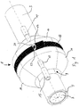
- Figure 1 shows a perspective schematic representation of a terminal 1, which is arranged around a main conductor 3.
- the main conductor 3 has an insulating jacket 5 which surrounds a multi-core cable harness 7.
- the cable harness 7 comprises four wires.
- the main conductor 3 is freed of its insulating jacket 5 in the area 9 of the connecting terminal, which leads to a narrowing of the diameter of the main conductor 3.
- the area 9 is surrounded by the connecting terminal 1, which has four clamping elements 11, three of which can be seen in FIG.
- clamping element 11 which is provided with openings 13, into each of which a branch conductor 15 is inserted.
- the other clamping elements 11 also have openings for the branch conductor 15.
- the four sector-shaped clamping elements 11 are surrounded by a band-shaped pipe clamp 17 which has a screw-shaped tightening element 19.
- a tear-off head screw 21 can be seen, in which the tear-off head has already been cut off and only a corresponding fracture surface 23 can be seen.
- the clamping elements 11 shown there have smooth outer surfaces, whereas, in an alternative embodiment according to FIG. 2, a clamping element 25 is shown which also has rib-shaped structures externally open recesses or cavities 27 is provided. Ribs 29 and 30 delimit these cavities 27.
- the clamping element 25 has a cross-sectionally narrowing projection region 33 on its end face 31, the tapering running in the direction of the outside or in the axial direction of the clamping element 25.
- the partially broken section A is described in connection with FIG. 6.
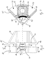
- Figure 3 shows a sectional view along the line III-III of Figure 2. From this sectional view, the structure of the clamping element 25, which is identical to the structure of the clamping element 11 except for the outer contour, is clear. For the sake of clarity, the illustration of the spring elements is omitted here and is shown in FIG. 5.
- a cavity 35 is formed in the clamping element 25, which is open from the inside 37 of the clamping element 25.
- a contact element 39 is inserted, which is designed so that it follows the contour of the cavity 35 on the one hand and the inside 37 of the clamping element 25 on the other.
- tooth-shaped contacts 43 are provided which taper towards the main conductor.
- a band-shaped sealing compound 45 is also provided on the underside 41 of the contact element 39.
- the clamping element 25 also has a wedge 47, which is used to secure the position of the clamping element 25 on the main conductor.
- a clamping element 25 with two projection areas 33 is shown schematically in a reduced form in FIG.
- the clamping element 25 has two wedges 47, which are arranged on the respective end regions of the clamping element 25. In between there is a free space 49, which is used in particular to insert the contact element 39 into the cavity 35 of the clamping element 25 from below.
- the band-shaped sealing compound 45 can be seen and, when viewed in conjunction with FIG. 3, it results that the tooth-shaped contacts 43 are arranged in three rows of 4 teeth each.
- FIG. 5 is a view of an insulated contact element 39 according to the invention, as shown in FIG. 3 as a part inserted into the clamping element 25. From Figure 5 an end opening 51 can be seen, which is explained in more detail with reference to FIG. 6.
- FIG. 6 shows a sectional view of the contact element 39 according to the invention along the line VI-VI from FIG. 5.
- the contact element 39 has a symmetrical design with two openings 51, the axes 53 and 54 of which coincide in this embodiment.
- a partition 55 is formed between the openings 51 and can serve as a stop for a branch conductor.
- spring elements 57 are provided, one of which is shown in a top view in FIG.
- the spring element 57 is ring-shaped, with notches 63 running from the inner edge 61 to the outer edge 65, which result in flexible spring devices in the form of tongues.
- the insulating jacket 5 is first in the area 9 of the terminals 1 removed so that the insulated of the multi-core main conductor 3 are accessible from the outside.
- a sector-shaped clamping element 11 or 25 after the other is inserted with the help of the wedge 47 between two wires of the main conductor 3 and is initially secured in position.
- the band-shaped pipe clamp 17 is placed around the clamping elements 11 and tightened by means of a tear-off head screw 21.
- the tooth-shaped contacts 43 penetrate into the insulating jacket of each wire, cut through it and hit the actual metallic conductor of the corresponding wire.
- the tear-off head of the tear-off head screw 21 tears off and the connecting terminal 1 is firmly mounted on the main conductor 3.
- the branch conductor 15 is inserted into the opening 13 or 51 and passes through one or more sets of spring elements 59.
- the spring tongues 67 deform and grind on the surface of the branch conductor 15 in such a way that the oxide layer thereon is severed and an electrical contact is made .
- the spring devices 67 jam on the branch conductor and prevent it from being pulled out of the opening 51 or 13 against its direction of insertion. This will make both a safe electrical Contact or a secure electrical connection is created and a secure anchoring of the branch conductor 15 in the opening of the clamping element 11 or 25 is ensured.
- the present invention is not limited to the described embodiments. Depending on the requirements, for example, more clamping elements can also be provided, for example in the case of main conductors with more than four wires.
- the contact element 39 has two openings 51. When using the connection terminal for only one branch, however, it is sufficient that only quasi half of the contact element 39 is provided, i. H. that only one opening 51 is provided.
- rings 57 can also be designed to be correspondingly variable.
- polygonal inner recesses of the rings could be provided, and the holding and contact effect of a spring element 57 may already be sufficient to hold the corresponding branch conductor securely in the contact element and to ensure the electrical connection.
Landscapes
- Cable Accessories (AREA)
- Connections Effected By Soldering, Adhesion, Or Permanent Deformation (AREA)
- Connections Arranged To Contact A Plurality Of Conductors (AREA)
- Coupling Device And Connection With Printed Circuit (AREA)
- Connections By Means Of Piercing Elements, Nuts, Or Screws (AREA)
Applications Claiming Priority (2)
| Application Number | Priority Date | Filing Date | Title |
|---|---|---|---|
| DE19539184 | 1995-10-20 | ||
| DE19539184A DE19539184C3 (de) | 1995-10-20 | 1995-10-20 | Kontaktelement zur Erzeugung eines elektrischen Kontaktes zwischen Hauptleiter und Abzweigleiter sowie Anschlußklemme mit diesem Kontaktelement |
Publications (3)
| Publication Number | Publication Date |
|---|---|
| EP0769825A2 true EP0769825A2 (fr) | 1997-04-23 |
| EP0769825A3 EP0769825A3 (fr) | 1998-02-25 |
| EP0769825B1 EP0769825B1 (fr) | 2008-09-10 |
Family
ID=7775407
Family Applications (1)
| Application Number | Title | Priority Date | Filing Date |
|---|---|---|---|
| EP96115829A Expired - Lifetime EP0769825B1 (fr) | 1995-10-20 | 1996-10-02 | Borne de connexion, en particulier pour la connexion de conducteurs de dérivation à un conducteur principal, et un élément de contact approprié |
Country Status (5)
| Country | Link |
|---|---|
| US (1) | US6045373A (fr) |
| EP (1) | EP0769825B1 (fr) |
| AT (1) | ATE408249T1 (fr) |
| DE (2) | DE19539184C3 (fr) |
| ES (1) | ES2332957T3 (fr) |
Cited By (4)
| Publication number | Priority date | Publication date | Assignee | Title |
|---|---|---|---|---|
| WO2007130811A2 (fr) | 2006-05-05 | 2007-11-15 | 3M Innovative Properties Company | Borne tubulaire d'un câble |
| EP2251936A1 (fr) * | 2009-03-24 | 2010-11-17 | GT Elektrotechnische Produkte GmbH | Borne de dérivation pour câble |
| EP2333904A1 (fr) * | 2009-12-11 | 2011-06-15 | Nexans | Dispositif de connexion électrique entre les conducteurs d'un cable fort courant et des fils de dérivation |
| EP2608338A1 (fr) | 2011-12-21 | 2013-06-26 | 3M Innovative Properties Company | Dispositif de raccordement de terminal pour câble d'alimentation |
Families Citing this family (7)
| Publication number | Priority date | Publication date | Assignee | Title |
|---|---|---|---|---|
| AUPO947297A0 (en) * | 1997-09-26 | 1997-10-23 | Mannesmann Dematic Colby Pty Limited | Paperless picking systems |
| DE20023929U1 (de) * | 2000-11-22 | 2007-09-20 | Pfisterer Kontaktsysteme Gmbh & Co. Kg | Vorrichtung zum gleichzeitigen elektrischen Verbinden der Hauptleiter einer Energieversorgungsleitung mit jeweils mindestens einem Abzweigleiter, insbesondere Schraubkompaktklemme |
| DE10205470C1 (de) * | 2002-02-08 | 2003-08-14 | Wieland Electric Gmbh | Anschlusskontakt |
| DE10205613B4 (de) * | 2002-02-11 | 2007-09-27 | Wieland Electric Gmbh | Kontaktelement |
| DE102007030134B3 (de) * | 2007-06-29 | 2008-10-02 | Rahnenführer, Dirk | Leitersteckverbinder |
| DE102008019971B3 (de) * | 2008-04-21 | 2009-07-16 | Rahnenführer, Dirk | Leitersteckverbinder |
| EP3014721A4 (fr) | 2013-06-26 | 2017-02-15 | 3M Innovative Properties Company | Dispositif de raccordement terminal de câble d'alimentation |
Citations (5)
| Publication number | Priority date | Publication date | Assignee | Title |
|---|---|---|---|---|
| US3383648A (en) * | 1965-08-20 | 1968-05-14 | Milton Ross Controls Co Inc | Miniature sockets |
| FR2135400A1 (fr) * | 1971-05-03 | 1972-12-22 | Simel | |
| LU78705A1 (fr) * | 1976-12-18 | 1978-04-17 | ||
| FR2656742A1 (fr) * | 1989-12-29 | 1991-07-05 | Materiel Electr Soc Ind | Element detrompeur pour dispositifs de connexion destines au branchement de derivations sur des cables principaux. |
| DE9201942U1 (fr) * | 1992-02-15 | 1992-04-02 | Kabelmetal Electro Gmbh, 3000 Hannover, De |
Family Cites Families (15)
| Publication number | Priority date | Publication date | Assignee | Title |
|---|---|---|---|---|
| US2395373A (en) * | 1943-07-17 | 1946-02-19 | Marvin H Johnson | Welded connector |
| FR2112661A5 (fr) * | 1970-11-05 | 1972-06-23 | Jeumont Schneider | |
| DE2227211A1 (de) * | 1972-06-05 | 1974-01-03 | Lipprandt | Mehrfachabzweigklemme |
| DE2344404A1 (de) * | 1973-09-03 | 1975-03-13 | Bertos Ag | Anschlussklemme mit einem geraeteanschluss- und einem aussenanschlusskontakt |
| US3875325A (en) * | 1974-06-10 | 1975-04-01 | Western Electric Co | Telephone splice closure |
| US3937548A (en) * | 1975-02-26 | 1976-02-10 | Amp Incorporated | Device for splicing wire |
| DE2651014C2 (de) * | 1976-11-09 | 1985-02-07 | Karl Pfisterer Elektrotechnische Spezialartikel Gmbh & Co Kg, 7000 Stuttgart | Klemme für einadrige elektrische Leiter |
| US4080024A (en) * | 1977-05-12 | 1978-03-21 | Harco Corporation | Underground cable connection |
| US4479692A (en) * | 1982-01-07 | 1984-10-30 | Thomas & Betts Corporation | Receptacle for flat multiconductor cable |
| DE3221458C1 (de) * | 1982-06-07 | 1987-12-23 | Franz Wirschitz GmbH Herstellung von Freileitungs- und Schaltanlagen-Armaturen, 8000 München | Verfahren zum Anschliessen von Abzweigleitern an Adern eines spannungsfuehrenden,elektrischen Kabels sowie Abzweigklemme zur Ausfuehrung dieses Verfahrens |
| DE3330630C1 (de) * | 1983-08-25 | 1984-10-18 | Karl Pfisterer Elektrotechnische Spezialartikel Gmbh & Co Kg, 7000 Stuttgart | Klemme |
| US4722579A (en) * | 1985-01-31 | 1988-02-02 | Steven Cummings | Electrical connector devices and methods |
| DE3933609A1 (de) * | 1989-10-07 | 1991-04-11 | Hollandse Apparatenfab | Kabelabzweigklemme |
| DE9011571U1 (fr) * | 1990-08-08 | 1991-01-03 | Gerhard Petri Gmbh + Co. Kg, 8670 Hof, De | |
| DE29512567U1 (de) * | 1995-08-04 | 1995-10-05 | Electro Terminal Gmbh | Schraubenlose Verbindungsklemme |
-
1995
- 1995-10-20 DE DE19539184A patent/DE19539184C3/de not_active Expired - Fee Related
-
1996
- 1996-10-02 EP EP96115829A patent/EP0769825B1/fr not_active Expired - Lifetime
- 1996-10-02 ES ES96115829T patent/ES2332957T3/es not_active Expired - Lifetime
- 1996-10-02 DE DE59611485T patent/DE59611485D1/de not_active Expired - Lifetime
- 1996-10-02 AT AT96115829T patent/ATE408249T1/de not_active IP Right Cessation
- 1996-10-18 US US08/733,980 patent/US6045373A/en not_active Expired - Fee Related
Patent Citations (5)
| Publication number | Priority date | Publication date | Assignee | Title |
|---|---|---|---|---|
| US3383648A (en) * | 1965-08-20 | 1968-05-14 | Milton Ross Controls Co Inc | Miniature sockets |
| FR2135400A1 (fr) * | 1971-05-03 | 1972-12-22 | Simel | |
| LU78705A1 (fr) * | 1976-12-18 | 1978-04-17 | ||
| FR2656742A1 (fr) * | 1989-12-29 | 1991-07-05 | Materiel Electr Soc Ind | Element detrompeur pour dispositifs de connexion destines au branchement de derivations sur des cables principaux. |
| DE9201942U1 (fr) * | 1992-02-15 | 1992-04-02 | Kabelmetal Electro Gmbh, 3000 Hannover, De |
Cited By (7)
| Publication number | Priority date | Publication date | Assignee | Title |
|---|---|---|---|---|
| WO2007130811A2 (fr) | 2006-05-05 | 2007-11-15 | 3M Innovative Properties Company | Borne tubulaire d'un câble |
| EP2251936A1 (fr) * | 2009-03-24 | 2010-11-17 | GT Elektrotechnische Produkte GmbH | Borne de dérivation pour câble |
| EP2333904A1 (fr) * | 2009-12-11 | 2011-06-15 | Nexans | Dispositif de connexion électrique entre les conducteurs d'un cable fort courant et des fils de dérivation |
| WO2011069852A1 (fr) * | 2009-12-11 | 2011-06-16 | Nexans | Dispositif destiné à relier de manière électriquement conductrice les conducteurs principaux d'un câble pour courants forts avec des conducteurs de dérivation |
| EP2608338A1 (fr) | 2011-12-21 | 2013-06-26 | 3M Innovative Properties Company | Dispositif de raccordement de terminal pour câble d'alimentation |
| WO2013096354A1 (fr) | 2011-12-21 | 2013-06-27 | 3M Innovative Properties Company | Dispositif de connexion de borne pour câble d'alimentation électrique |
| EP2698891A1 (fr) | 2011-12-21 | 2014-02-19 | 3M Innovative Properties Company | Dispositif de connexion de borne pour un câble électrique |
Also Published As
| Publication number | Publication date |
|---|---|
| ATE408249T1 (de) | 2008-09-15 |
| DE59611485D1 (de) | 2008-10-23 |
| US6045373A (en) | 2000-04-04 |
| EP0769825A3 (fr) | 1998-02-25 |
| EP0769825B1 (fr) | 2008-09-10 |
| ES2332957T3 (es) | 2010-02-15 |
| DE19539184C3 (de) | 2002-12-12 |
| DE19539184A1 (de) | 1997-04-24 |
| DE19539184C2 (de) | 1999-03-11 |
Similar Documents
| Publication | Publication Date | Title |
|---|---|---|
| DE19951455C1 (de) | Kabelanschluss- oder -verbindungseinrichtung | |
| DE19738517C1 (de) | Kabelverschraubung für Erdungs- oder Abschirmkabel mit einem gegen das Kabel preßbaren Klemmeinsatz | |
| WO2015185511A2 (fr) | Appareil électrique | |
| EP1885025A2 (fr) | Dispositif de raccordement électrique d'au moins deux conducteurs principaux isolés d'un câble d'alimentation électrique, en particulier borne de dérivation | |
| EP3329566B1 (fr) | Dispositif antidéflagrant et procédé de fabrication de celui-ci | |
| EP2577805A1 (fr) | Élément de contact pour ensemble connecteur | |
| EP0769825A2 (fr) | Borne de connexion, en particulier pour la connexion de conducteurs de dérivation à un conducteur principal, et un élément de contact approprié | |
| EP1158610B1 (fr) | Connecteur de câble enfichable | |
| EP0156956B1 (fr) | Dispositif de maintien d'un câble électrique dans un boîtier de connexion | |
| DE102014200133A1 (de) | Vorrichtung zur Fixierung einer elektrischen Leitung in einem Stecker, Stecker für eine elektrische Leitung sowie elektrisches Kabel | |
| DE2305403C3 (de) | Lötfreie Anschlußstelle | |
| EP3688851B1 (fr) | Passe-câble à vis | |
| EP0695008B1 (fr) | Dispositif de blocage de câble universel | |
| DD156210A1 (de) | Universalmuffe fuer fernmelde-bzw.starkstromkabel | |
| DE10341997A1 (de) | Vorrichtung zum elektrischen Verbinden von mindestens zwei isolierten Hauptleitern eines Energieversorgungskabels, insbesondere Kabelabzweigklemme | |
| EP0285079B1 (fr) | Dispositif de serrage pour la réalisation d'une dérivation sur les conducteurs d'un câble de tension et réalisation d'une telle dérivation | |
| DE102013113878B4 (de) | Steckverbinder mit Einzeladerabdichtung | |
| EP1699122A2 (fr) | Boîte pour une connexion de câble | |
| DE19615951C1 (de) | Mehrphasige Klemmvorrichtung | |
| WO2004105185A1 (fr) | Element de contact et chambre de conduction complementaire pour un connecteur male ou femelle utilise en technique de raccordement autodenudant | |
| DE3116027A1 (de) | Elektrischer steckverbinder | |
| DE4217906C2 (de) | Kabeleinführungstülle zum Einführen eines Kabels in ein Gehäuse oder dergleichen | |
| EP0422484A2 (fr) | Borne de dérivation pour câble | |
| DE19757862A1 (de) | Kabelkupplung | |
| DE3743268C2 (fr) |
Legal Events
| Date | Code | Title | Description |
|---|---|---|---|
| PUAI | Public reference made under article 153(3) epc to a published international application that has entered the european phase |
Free format text: ORIGINAL CODE: 0009012 |
|
| AK | Designated contracting states |
Kind code of ref document: A2 Designated state(s): AT BE CH DE DK ES FR GB IT LI LU NL PT SE |
|
| PUAL | Search report despatched |
Free format text: ORIGINAL CODE: 0009013 |
|
| AK | Designated contracting states |
Kind code of ref document: A3 Designated state(s): AT BE CH DE DK ES FR GB IT LI LU NL PT SE |
|
| 17P | Request for examination filed |
Effective date: 19980817 |
|
| 17Q | First examination report despatched |
Effective date: 20001218 |
|
| RAP1 | Party data changed (applicant data changed or rights of an application transferred) |
Owner name: GERHARD PETRI GMBH & CO. KG |
|
| APBN | Date of receipt of notice of appeal recorded |
Free format text: ORIGINAL CODE: EPIDOSNNOA2E |
|
| APBR | Date of receipt of statement of grounds of appeal recorded |
Free format text: ORIGINAL CODE: EPIDOSNNOA3E |
|
| APAF | Appeal reference modified |
Free format text: ORIGINAL CODE: EPIDOSCREFNE |
|
| APBT | Appeal procedure closed |
Free format text: ORIGINAL CODE: EPIDOSNNOA9E |
|
| GRAP | Despatch of communication of intention to grant a patent |
Free format text: ORIGINAL CODE: EPIDOSNIGR1 |
|
| RAP1 | Party data changed (applicant data changed or rights of an application transferred) |
Owner name: GPH GMBH |
|
| GRAS | Grant fee paid |
Free format text: ORIGINAL CODE: EPIDOSNIGR3 |
|
| GRAA | (expected) grant |
Free format text: ORIGINAL CODE: 0009210 |
|
| AK | Designated contracting states |
Kind code of ref document: B1 Designated state(s): AT BE CH DE DK ES FR GB IT LI LU NL PT SE |
|
| REG | Reference to a national code |
Ref country code: GB Ref legal event code: FG4D Free format text: NOT ENGLISH |
|
| REG | Reference to a national code |
Ref country code: CH Ref legal event code: EP |
|
| REF | Corresponds to: |
Ref document number: 59611485 Country of ref document: DE Date of ref document: 20081023 Kind code of ref document: P |
|
| PGFP | Annual fee paid to national office [announced via postgrant information from national office to epo] |
Ref country code: NL Payment date: 20081015 Year of fee payment: 13 |
|
| PGFP | Annual fee paid to national office [announced via postgrant information from national office to epo] |
Ref country code: ES Payment date: 20081027 Year of fee payment: 13 |
|
| PGFP | Annual fee paid to national office [announced via postgrant information from national office to epo] |
Ref country code: BE Payment date: 20081120 Year of fee payment: 13 |
|
| PGFP | Annual fee paid to national office [announced via postgrant information from national office to epo] |
Ref country code: FR Payment date: 20081014 Year of fee payment: 13 |
|
| PG25 | Lapsed in a contracting state [announced via postgrant information from national office to epo] |
Ref country code: PT Free format text: LAPSE BECAUSE OF FAILURE TO SUBMIT A TRANSLATION OF THE DESCRIPTION OR TO PAY THE FEE WITHIN THE PRESCRIBED TIME-LIMIT Effective date: 20090210 |
|
| REG | Reference to a national code |
Ref country code: CH Ref legal event code: PL |
|
| PGFP | Annual fee paid to national office [announced via postgrant information from national office to epo] |
Ref country code: GB Payment date: 20081021 Year of fee payment: 13 |
|
| PLBE | No opposition filed within time limit |
Free format text: ORIGINAL CODE: 0009261 |
|
| STAA | Information on the status of an ep patent application or granted ep patent |
Free format text: STATUS: NO OPPOSITION FILED WITHIN TIME LIMIT |
|
| PG25 | Lapsed in a contracting state [announced via postgrant information from national office to epo] |
Ref country code: DK Free format text: LAPSE BECAUSE OF FAILURE TO SUBMIT A TRANSLATION OF THE DESCRIPTION OR TO PAY THE FEE WITHIN THE PRESCRIBED TIME-LIMIT Effective date: 20080910 |
|
| 26N | No opposition filed |
Effective date: 20090611 |
|
| PG25 | Lapsed in a contracting state [announced via postgrant information from national office to epo] |
Ref country code: IT Free format text: LAPSE BECAUSE OF FAILURE TO SUBMIT A TRANSLATION OF THE DESCRIPTION OR TO PAY THE FEE WITHIN THE PRESCRIBED TIME-LIMIT Effective date: 20080910 |
|
| PG25 | Lapsed in a contracting state [announced via postgrant information from national office to epo] |
Ref country code: LI Free format text: LAPSE BECAUSE OF NON-PAYMENT OF DUE FEES Effective date: 20081031 Ref country code: CH Free format text: LAPSE BECAUSE OF NON-PAYMENT OF DUE FEES Effective date: 20081031 |
|
| PG25 | Lapsed in a contracting state [announced via postgrant information from national office to epo] |
Ref country code: SE Free format text: LAPSE BECAUSE OF FAILURE TO SUBMIT A TRANSLATION OF THE DESCRIPTION OR TO PAY THE FEE WITHIN THE PRESCRIBED TIME-LIMIT Effective date: 20081210 Ref country code: AT Free format text: LAPSE BECAUSE OF NON-PAYMENT OF DUE FEES Effective date: 20081002 |
|
| REG | Reference to a national code |
Ref country code: ES Ref legal event code: FG2A Ref document number: 2332957 Country of ref document: ES Kind code of ref document: T3 |
|
| BERE | Be: lapsed |
Owner name: GPH G.M.B.H. Effective date: 20091031 |
|
| REG | Reference to a national code |
Ref country code: NL Ref legal event code: V1 Effective date: 20100501 |
|
| PG25 | Lapsed in a contracting state [announced via postgrant information from national office to epo] |
Ref country code: LU Free format text: LAPSE BECAUSE OF NON-PAYMENT OF DUE FEES Effective date: 20081002 |
|
| REG | Reference to a national code |
Ref country code: FR Ref legal event code: ST Effective date: 20100630 |
|
| PG25 | Lapsed in a contracting state [announced via postgrant information from national office to epo] |
Ref country code: NL Free format text: LAPSE BECAUSE OF NON-PAYMENT OF DUE FEES Effective date: 20100501 Ref country code: FR Free format text: LAPSE BECAUSE OF NON-PAYMENT OF DUE FEES Effective date: 20091102 |
|
| PGFP | Annual fee paid to national office [announced via postgrant information from national office to epo] |
Ref country code: DE Payment date: 20100326 Year of fee payment: 14 |
|
| PG25 | Lapsed in a contracting state [announced via postgrant information from national office to epo] |
Ref country code: BE Free format text: LAPSE BECAUSE OF NON-PAYMENT OF DUE FEES Effective date: 20091031 |
|
| PG25 | Lapsed in a contracting state [announced via postgrant information from national office to epo] |
Ref country code: GB Free format text: LAPSE BECAUSE OF NON-PAYMENT OF DUE FEES Effective date: 20091002 |
|
| REG | Reference to a national code |
Ref country code: ES Ref legal event code: FD2A Effective date: 20110303 |
|
| PG25 | Lapsed in a contracting state [announced via postgrant information from national office to epo] |
Ref country code: ES Free format text: LAPSE BECAUSE OF NON-PAYMENT OF DUE FEES Effective date: 20110302 |
|
| REG | Reference to a national code |
Ref country code: DE Ref legal event code: R119 Ref document number: 59611485 Country of ref document: DE Effective date: 20110502 |
|
| PG25 | Lapsed in a contracting state [announced via postgrant information from national office to epo] |
Ref country code: ES Free format text: LAPSE BECAUSE OF NON-PAYMENT OF DUE FEES Effective date: 20091003 |
|
| PG25 | Lapsed in a contracting state [announced via postgrant information from national office to epo] |
Ref country code: DE Free format text: LAPSE BECAUSE OF NON-PAYMENT OF DUE FEES Effective date: 20110502 |