EP0769737B1 - Drucker und Verfahren mit Steuerfunktion für externe Geräte - Google Patents
Drucker und Verfahren mit Steuerfunktion für externe Geräte Download PDFInfo
- Publication number
- EP0769737B1 EP0769737B1 EP96116193A EP96116193A EP0769737B1 EP 0769737 B1 EP0769737 B1 EP 0769737B1 EP 96116193 A EP96116193 A EP 96116193A EP 96116193 A EP96116193 A EP 96116193A EP 0769737 B1 EP0769737 B1 EP 0769737B1
- Authority
- EP
- European Patent Office
- Prior art keywords
- control
- data
- command
- external device
- predetermined
- Prior art date
- Legal status (The legal status is an assumption and is not a legal conclusion. Google has not performed a legal analysis and makes no representation as to the accuracy of the status listed.)
- Expired - Lifetime
Links
Images


Classifications
-
- G—PHYSICS
- G06—COMPUTING OR CALCULATING; COUNTING
- G06F—ELECTRIC DIGITAL DATA PROCESSING
- G06F3/00—Input arrangements for transferring data to be processed into a form capable of being handled by the computer; Output arrangements for transferring data from processing unit to output unit, e.g. interface arrangements
- G06F3/12—Digital output to print unit, e.g. line printer, chain printer
- G06F3/1201—Dedicated interfaces to print systems
- G06F3/1202—Dedicated interfaces to print systems specifically adapted to achieve a particular effect
- G06F3/1203—Improving or facilitating administration, e.g. print management
- G06F3/1204—Improving or facilitating administration, e.g. print management resulting in reduced user or operator actions, e.g. presetting, automatic actions, using hardware token storing data
-
- G—PHYSICS
- G06—COMPUTING OR CALCULATING; COUNTING
- G06F—ELECTRIC DIGITAL DATA PROCESSING
- G06F3/00—Input arrangements for transferring data to be processed into a form capable of being handled by the computer; Output arrangements for transferring data from processing unit to output unit, e.g. interface arrangements
- G06F3/12—Digital output to print unit, e.g. line printer, chain printer
- G06F3/1201—Dedicated interfaces to print systems
- G06F3/1223—Dedicated interfaces to print systems specifically adapted to use a particular technique
- G06F3/1229—Printer resources management or printer maintenance, e.g. device status, power levels
-
- G—PHYSICS
- G06—COMPUTING OR CALCULATING; COUNTING
- G06F—ELECTRIC DIGITAL DATA PROCESSING
- G06F3/00—Input arrangements for transferring data to be processed into a form capable of being handled by the computer; Output arrangements for transferring data from processing unit to output unit, e.g. interface arrangements
- G06F3/12—Digital output to print unit, e.g. line printer, chain printer
- G06F3/1201—Dedicated interfaces to print systems
- G06F3/1278—Dedicated interfaces to print systems specifically adapted to adopt a particular infrastructure
- G06F3/1279—Controller construction, e.g. aspects of the interface hardware
-
- G—PHYSICS
- G07—CHECKING-DEVICES
- G07G—REGISTERING THE RECEIPT OF CASH, VALUABLES, OR TOKENS
- G07G5/00—Receipt-giving machines
-
- G—PHYSICS
- G06—COMPUTING OR CALCULATING; COUNTING
- G06K—GRAPHICAL DATA READING; PRESENTATION OF DATA; RECORD CARRIERS; HANDLING RECORD CARRIERS
- G06K2215/00—Arrangements for producing a permanent visual presentation of the output data
- G06K2215/0002—Handling the output data
- G06K2215/0005—Accepting output data; Preparing data for the controlling system
Definitions
- the present invention relates to a printing apparatus having a cash drawer control function and to a control method therefor. More particularly, the invention relates to a printing apparatus capable of controlling a cash drawer irrespective of the status of the printing apparatus.
- the present invention is therefore particularly effective when used with systems for processing monetary transactions, such as point-of-sale (POS) terminals and electronic cash registers (ECR).
- POS point-of-sale
- ECR electronic cash registers
- POS and ECR systems typically have the cash drawer in which money is held below the printing apparatus.
- the cash drawer is normally locked in a closed condition and opens in response to a cash drawer open/close signal issued from the printing apparatus.
- So-called terminal printing apparatuses that are connected through some interface to a host device to execute a printing process according to control commands received from the host device, comprise means for outputting the cash drawer open/close signal for a specified time from a specified output port. To reduce the standby time to completion of the control commands of the host device, the control commands are temporarily stored in a command buffer, and then read and executed in first-in-first-out order.
- command buffer size varies according to the model and application of the printing apparatus
- the command buffer is often also used as a print data buffer, and can therefore generally store a large number of control commands. Therefore, when many control commands are stored in the command buffer, a significant time interval may pass from the time at which the host device sends a cash drawer open command until the cash drawer is actually opened. More specifically, once a receipt printing or other printing process has been started, monetary transactions such as storing cash received or making customer change must wait until the printing process is completed. As a result, the user must wait for an extended period of time, and numerous problems therefore remain for printing apparatuses used in systems for processing monetary transactions, such as point-of-sale (POS) terminals and electronic cash registers (ECR).
- POS point-of-sale
- ECR electronic cash registers
- WO-A-8201609 discloses a POS terminal comprising a control unit, one or more keyboards as data input means, a journal printer, a receipt printer and a display as data output means, and control means for opening a cash drawer.
- command detection means is part of printer control means and receives and interpretes control commands read out of a data storage means.
- One or more such POS terminals are connected via a respective interface to a central host computer.
- the POS terminal itself is a dump terminal which is controlled by the host computer. Data entered via a keyboard at the POS terminal is sent to the host computer which responds by sending back control commands and data for display and/or printing.
- the control unit in the POS terminal serves as both, a buffer memory for ingoing and outgoing data and a switching network for distributing control commands and data received from the host computer to the respective units.
- the cash drawer is opened under the control of the host computer when an appropriate code is received. No detail regarding the structure and detailed functioning of how buffered data are distributed to the individual units are disclosed in this document.
- EP-A-O 652 533 discloses a printing apparatus adapted to report certain status information to the host device it is connected to.
- the document discloses use of a first and a second command interpreter, one for interpreting commands read out of a FIFO buffer and the other for interpreting so-called real-time commands that bypass the FIFO buffer.
- An object of the present invention is to provide a printing apparatus whereby the above problems can be solved, the load on the host device is reduced and operation is user-friendly.
- the configuration of the invention it is possible to independently control an externally connected device as requested by the host device even when command data for the printing process are stored in the data storage means.
- the invention provides for protecting the controlled external device from being oveloaded by a sequence of control commands following one another at a short interval.
- the process sequence is preferably set with consideration to the power supply capacity, the processing capacity of the printing apparatus and other considerations. More specifically, if there is sufficient power supply capacity, simultaneously executing control of both the printing apparatus and an external device is preferable with respect to processing speed: On the other hand, temporarily interrupting the printing process and controlling the external device is preferable in applications in which controlling the external device is of higher priority. However, if interrupting the printing process will degrade the print quality, it is preferable to let the external device wait for a break point in the printing process that will not result in degraded print quality, such as at a line end.
- the command data received in one-byte units from the host device can be detected and processed as they are received. It is therefore not necessary to store a specific number of bytes of command data, and the time required for the detection process can be divided into small pieces. Therefore, if either the data receiving means or the command detection means interrupts printing process control by the printer control means to at least either receive data from the host device or detect the predetermined command data, the benefits of distributing the detection process can be obtained.
- Fig. 1 is a block diagram of the control circuit of a printing apparatus suitable for an embodiment of the invention.
- CPU 50 which controls the entire printing apparatus are: cover sensor 54 for detecting whether the cover of the printing apparatus is open; panel switch 49 for manual paper feed control; interface 51 for connection to host computer 61; ROM 52 for storing the control program 52a, character print patterns and other data: and RAM 53 used as a receive buffer 64, a print buffer 66 etc..
- Print data and command data input through interface 51 are stored in receive buffer 64 of RAM 53.
- CPU 50 interprets these data, reads, in case of print data (e.g. a character code), the corresponding character print pattern from ROM 52, and controls, in case of a print, format or positioning command, print controller 43 to accomplish the printing process. More specifically, CPU 50 controls, via print controller 43, ink jet head or other print head 40, and motor group 41 for driving print head 40 and a recording medium; and drives plungers of plunger group 42 to hold cut-sheet forms or switch a recording medium transport path as necessary when the printing apparatus is designed to print to plural media.
- print data e.g. a character code
- Pulse output commands for requesting supply of a control or drive pulse to a cash drawer or other external device connected to the printing apparatus are also input through interface 51.
- CPU 50 In response to a pulse output command CPU 50 outputs a pulse from port 56 or port 57 through drawer drive circuit 55. Which port is used for pulse output is specified by a parameter of the pulse output command as will be described below.
- the pulse output command is a real-time command. A real-time command is immediately executed even if previously entered commands are still waiting for execution in receive buffer 64.
- An example of a real-time command code is: DLE DC4 n m t.
- Each of the command code components DLE, DC4 and the values n, m and t is one byte expressed in hexadecimal notation as 10 H , 14 H , and the hexadecimal value corresponding to n, m and t.
- DLE and DC4 identify a real-time command.
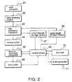
- Fig. 2 is a functional block diagram suitable for an embodiment of the present invention, and shows the relationship between its various functional means.
- Host computer 61 transfers command data and print data to the printing apparatus.
- Data receiving means 62 receives the data from host computer 61 through interface 51, and is implemented in the present embodiment by means of an interrupt process started by interface 51. The received data are interpreted immediately upon being received by first command interpreter 63 implemented as part of the interrupt process for data receiving means 62.
- First command interpreter 63 checks whether the received data represent a real-time command and, if so, causes the specified process to be executed according to the command parameters. All data having been interpreted by first command interpreter 63 are stored temporarily in receive buffer 64. Second command interpreter 65 reads the stored data in a first-in-first-out sequence in single data units, e.g., one byte at a time, interprets the data and discriminates print data from command data used to set various printing apparatus control parameters. The interpretation of the data stored in receive buffer 64 by second command interpreter 65 is executed in response to a request from control means 69.
- control means 69 repeats checking whether receive buffer 64 is empty in a normal idling routine. If there are data in receive buffer 64, control means 69 causes second command interpreter to perform the interpretation described above.
- the data from data receiving means 62 is stored in receive buffer 64 after having been processed by first command interpreter 63
- the present invention shall not be so limited. It is also possible, for example, to store the data from data receiving means 62 in receive buffer 64 while passing these data to first command interpreter 63 in parallel.
- Command data are processed by control means 69. More specifically, particular settings are made according to the command data, or particular operations are performed. If the received data is print data, a character print pattern is stored in print buffer 66 according to the data code. When printing is executed by control means 69, the print pattern is read from print buffer 66 to control print unit 70 and print.
- Print unit 70 comprises primarily print controller 43, print head 40, motor group 41 and plunger group 42 shown in Fig. 1.
- first command interpreter 63 When first command interpreter 63 confirms that the received data is a pulse output command, information indicating that a pulse output request was received is stored in storage means 67 of RAM 53. This can be accomplished, for example, by setting a particular flag. In the following this information will be referred to as "request flag".
- the pulse length is also stored in storage means 68.
- the output port number, another parameter of the command, may be separately stored in another storage means (area of RAM 53) or a respective request flag is provided for each port number.
- Control means 69 monitors the request flag by polling storage means 67. When the request flag (or one of the request flags) is set, control means 69 outputs, by means of pulse generator 71, a pulse of a length according to the information in storage means 68 to the port whose number has been stored in RAM 53 (or which is associated with the request flag that is found to be set).
- control means 69 When the cover of the printing apparatus is open or paper is being transferred in response to paper transport switch 49 having been actuated, control means 69 comes in a so-called off-line state where it waits for the off-line state to be cancelled. More specifically, reading and executing commands from receive buffer 64 stops to assure operator safety when the printing apparatus cover is open to supply paper, for example. Because receive buffer 64 may overflow if data continue to be stored in receive buffer 64 in this state, the printing apparatus notifies the host device that data sent thereafter are not guaranteed to be received.
- control means 69 When control means 69 is in the off-line state, control means 69 only monitors data input from data receiving means 62, and cannot activate the second command interpreter 65.
- the first command interpreter 63 continues to operate irrespective of the off-line status while control means 69 monitors data input.
- a current pulse for driving a solenoid built into the cash drawer is output in response to the pulse output command; furthermore, pulse generator 71 and print unit 70 share the same power supply. Because the power supply does not have sufficient capacity to simultaneously drive both the solenoid via pulse generator 71 and print unit 70, control means 69 can only drive one of the devices, i.e., either printing is performed or pulse generation.
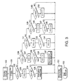
- Fig. 3 shows the control sequence of the receive interrupt process of the interface by which the data receiving means 62 and real-time command interpreter 63 are implemented.
- Data sent from the host computer through interface 51 are received in data units of a particular size, which is defined as one byte by way of example only in the present embodiment.
- the process shown in Fig. 3 is therefore executed each time one data byte is received.
- the process starts at step 130 when a byte C has been received and a receive interrupt generated by interface 51.
- step 134 If the value of C is from 1 to 8 (step 134), it is stored as pulse length (or representation of the pulse length) at a specific address in RAM 53 in step 135 (as will be understood the specific address corresponds to storage means 68 in Fig. 2). Note that all received data are initially stored in receive buffer 64, even real-time commands (step 151).
- step 134 If the value C is outside the range from 1 to 8 (step 134), the counter remains cleared and the byte is stored to receive buffer 64 (step 151). Such values are illegal parameters and therefore prohibit the complete command from being processed. The byte is nevertheless stored to receive buffer 64 because it may be part of print data.
- a value of n other than 1 may represent a different real-time command for execution of some other process with priority over normal commands. Because other real-time processes are not defined in the present embodiment, no real-time processing is performed if n ⁇ 1.
- step 149 it is determined whether C is 10 H (the DLE code) (step 149). If C is 10 H , RTC is set to 1 (step 150); if not, the byte is stored to the receive buffer (step 151) and the receive interrupt process is terminated (step 152). If in step 149 the value of C is not 10 H , the counter remains cleared and the byte is written to the receive buffer (step 151).
- Control means 69 monitors the request flag stored in storage means 67, and reads the pulse length from storage means 68 (step 101) when a request flag is detected to be set (step 100 returns YES).
- the port number for pulse output is read from a corresponding storage means (or determined from the request flag) (step 102), and the pulse is output (step 103 or step 104).
- a timer for counting the ON time is activated (step 105), the process waits for the ON time (step 106), pulse output to the port is then stopped (step 107), an OFF time counter is started (step 108), and the process waits for the OFF time (step 109).
- the output request flag for the port for which an output request was issued is cleared (step 110), and the process loops back to step 100 to determine whether the next output request was received. If there is no output request, the process continues to look for the next output request.
- the OFF time in the present embodiment is set to the same time as the ON time specified by command. It is also possible, however, to set the OFF time by means of a command parameter using a process similar to that described above. Note that the OFF time is set and pulse output requests are effectively prohibited during this OFF time period to limit the drive duty of the control object. More specifically, if an OFF time is not defined and commands are transferred continuously, the ON state duty of the control pulse may be excessively large.
- the pulse output process shown in Fig. 4 is executed during the standby loop of the printing apparatus control program executed by CPU 50. This loop is not executed during the printing process, and the pulse output process is therefore not executed. In this case, the pulse output process is executed when one printing process is completed and the control program returns to the standby loop before starting the next process.
- the process can be executed by means of an internal interrupt, timer interrupt, or other known interrupt process.
- the printing process and pulse output process can be executed in parallel. More specifically, the ON time wait period (step 106) and the OFF time wait period (step 109) in Fig. 4 can be used to easily achieve parallel printing and pulse output processes by means of time-shared printing control. Furthermore, the printing process functions can be handled by print controller 43 using a micro-controller, for example, and the pulse output process can be executed in parallel by CPU 50.
Landscapes
- Engineering & Computer Science (AREA)
- Theoretical Computer Science (AREA)
- Physics & Mathematics (AREA)
- General Physics & Mathematics (AREA)
- Human Computer Interaction (AREA)
- General Engineering & Computer Science (AREA)
- Accessory Devices And Overall Control Thereof (AREA)
Claims (13)
- Druckapparat, umfassend:dadurch gekennzeichnet, daß der Druckapparat ferner umfaßt:Datenempfangsmittel (51, 62) zum Empfangen von Druckdaten und Steuerbefehlen von einer Hosteinrichtung (61),Datenspeichermittel (53, 64) zum Speichern von Druckdaten und Steuerbefehlen, die durch die Datenempfangsmittel (51, 62) empfangen werden,Druckersteuermittel (50, 69) zum Lesen von Druckdaten und Steuerbefehlen, die in den Datenspeichermitteln gespeichert sind, in einer FIFO-Reihenfolge und zur entsprechenden Steuerung eines Druckprozesses,Befehlserfassungsmittel (50, 63), die auf die Datenempfangsmittel ansprechen, um einen vorbestimmten unter den Steuerbefehlen zu erfassen, die direkt ohne Zwischenschaltung der Datenspeichermittel (53, 64) von den Datenempfangsmitteln (51, 62) empfangen werden, undSteuermittel (50, 55, 71) für eine externe Einrichtung zur Steuerung einer externen Einrichtung, die mit dem Druckapparat verbunden ist, nach Maßgabe eines Steuerbefehls, der von den Datenempfangsmitteln (51, 62) empfangen wird,zwei oder mehr Impulsgeneratoreinrichtungen,Wählmittel zum Auswählen einer der zwei oder mehr Impulsgeneratoreinrichtungen nach Maßgabe des vorbestimmten Steuerbefehls, undInformationsspeichermittel (67,68),wobei die Befehlserfassungsmittel (50, 63) beschaffen sind, wenn sie den vorbestimmten Steuerbefehl erfassen, in den Informationsspeichermitteln (67,68) eine Steuerausgabeanforderung zu speichern, die anzeigt, daß eine Steuerung der externen Einrichtung angefordert wurde,die Steuermittel (50, 55, 71) für die externe Einrichtung als Antwort auf die in den Informationsspeichermitteln (67, 68) gespeicherte Steuerausgabeanforderung die ausgewählte der Impulsgeneratoreinrichtungen veranlaßt, ein Steuersignal an die externe Einrichtung auszugeben, wobei die Länge des Steuersignals abhängig von dem vorbestimmten Steuerbefehl festgelegt wird, unddie Steuermittel (50, 55, 71) für die externe Einrichtung beschaffen sind, zu verhindern, daß ein weiteres Steuersignal an die externe Einrichtung innerhalb einer vorbestimmten AUS-Zeit nach dem Ende des Steuersignals ausgegeben wird.
- Apparat nach Anspruch 1, bei dem die Steuermittel (50, 55, 71) für die externe Einrichtung beschaffen sind, die externe Einrichtung parallel zum Betrieb der Druckersteuermittel (50, 69) zu steuern.
- Apparat nach Anspruch 1, bei dem die Steuermittel (50, 55, 71) für die externe Einrichtung beschaffen sind, die externe Einrichtung mit Priorität gegenüber dem Betrieb der Druckersteuermittel (50, 69) zu steuern.
- Apparat nach Anspruch 1, bei dem die Steuermittel (50, 55, 71) für die externe Einrichtung beschaffen sind, die externe Einrichtung nach dem Ende eines von den Druckersteuermitteln (50, 69) gesteuerten Druckprozesses zu steuern, wenn solch ein Druckprozeß ausgeführt wird, während der vorbestimmte Steuerbefehl erfaßt wird.
- Apparat nach Anspruch 1, bei dem die externe Einrichtung eine Kassenlade ist und die Steuermittel für die externe Einrichtung Mittel zur Steuerung des Öffnens der Kassenlade sind.
- Apparat nach Anspruch 1, bei dem
die Datenempfangsmittel (51, 62) die Steuerbefehle von der Hosteinrichtung (61) in Dateneinheiten bekannter Größe empfangen,
der vorbestimmte Steuerbefehl mehrere Dateneinheiten umfaßt, und
die Befehlserfassungsmittel (50, 63) umfassen:einen Zähler zum Zählen der Anzahl von Dateneinheiten, undVergleichsmittel zum Vergleichen jeder Dateneinheit, die von den Datenempfangsmitteln empfangen wurde, mit einer jeweiligen Dateneinheit des Befehlsmusters des vorbestimmten Steuerbefehls, wobei die jeweilige Dateneinheit abhängig vom Zählwert des Zählers bestimmt wird. - Apparat nach Anspruch 6, bei dem die Datenempfangsmittel (51, 62) und/oder die Befehlserfassungsmittel (50, 63) beschaffen sind, einen Druckprozeß, der von den Druckersteuermitteln (50, 69) gesteuert wird, zu unterbrechen, um Daten von der Hosteinrichtung zu empfangen und/oder den vorbestimmten Steuerbefehl zu erfassen.
- Verfahren zur Steuerung eines Druckapparats, umfassend die Schrittedadurch gekennzeichnet, daß(a) Empfangen von Druckdaten und Steuerbefehlen von einer Hosteinrichtung,(b) Speichern von Druckdaten und Steuerbefehlen, die im Schritt (a) empfangen wurden,(c) Auslesen der Druckdaten und Steuerbefehle, die im Schritt (b) gespeichert wurden, in einer FIFO-Reihenfolge und Steuern eines Druckprozesses nach Maßgabe der Befehlsdaten,(d) Feststellen, vor Schritt (b), ob irgendeiner der Steuerbefehle, die im Schritt (a) empfangen werden, ein vorbestimmter Steuerbefehl ist, und(e) Steuern einer externen Einrichtung, die mit dem Druckapparat verbunden ist, nach Maßgabe eines im Schritt (a) empfangenen Steuerbefehls,
Schritt (d) das Speichern von externer Steuerinformation, die anzeigt, daß eine Steuerung der externen Einrichtung angefordert wurde, in Informationsspeichermitteln (67,68) umfaßt, wenn der vorbestimmte Steuerbefehl erfaßt wird, und
Schritt (e) umfaßt(e1) wiederholtes Abfragen der Informationsspeichermittel (67, 68) und Feststellen, ob oder ob nicht die externe Steuerinformation in den Informationsspeichermitteln (67, 68) gespeichert ist,
Wiederholen von Schritt (e1), wenn keine externe Steuerinformation gespeichert ist, und andernfalls:(e2) Treffen einer Auswahl unter zwei oder mehr Impulsgeneratoren nach Maßgabe des vorbestimmten Steuerbefehls,(e3) Veranlassen, daß der im Schritt (e2) ausgewählte Impulsgenerator beginnt, ein Steuersignal an die externe Einrichtung auszugeben,(e4) Veranlassen, daß der Impulsgenerator die Ausgabe des Steuersignals stoppt, nachdem eine vorbestimmte Zeit, die nach Maßgabe des vorbestimmten Steuerbefehls eingestellt ist, seit dem Start in Schritt (e3) abgelaufen ist,(e5) Zählen einer vorbestimmten AUS-Zeit als Antwort auf das Ende des Steuersignals, und
Verhindern, daß ein weiteres Steuersignal an die externe Einrichtung ausgegeben wird, während die AUS-Zeit gezählt wird, und(e6) Löschen der Informationsspeichermittel (67, 68) nach Ablauf der AUS-Zeit. - Verfahren nach Anspruch 8, bei dem Schritt (e) parallel mit der Steuerung in Schritt (c) ausgeführt wird.
- Verfahren nach Anspruch 8, bei dem Schritt (e) mit Priorität gegenüber der Steuerung im Schritt (c) ausgeführt wird.
- Verfahren nach Anspruch 8, bei dem Schritt (e) nach dem Ende eines Druckprozesses ausgeführt wird, wenn ein Druckprozeß gerade ausgeführt wird.
- Verfahren nach Anspruch 8, bei dem
Schritt (a) umfaßt, die Steuerbefehle in Dateneinheiten einer bekannten Größe zu empfangen, wobei der vorbestimmte Steuerbefehl mehrere Dateneinheiten umfaßt, und
Schritt (d) umfaßt:(d1) Zählen der Anzahl von Dateneinheiten, und(d2) Vergleichen jeder Dateneinheit, die im Schritt (a) empfangen wird, mit einer jeweiligen Dateneinheit des Befehlsmusters des vorbestimmten Steuerbefehls, wobei die jeweilige Dateneinheit nach Maßgabe der im Schritt (d1) gezählten Anzahl bestimmt wird. - Verfahren nach Anspruch 12, bei dem Schritt (a) und/oder Schritt (d) ausgeführt werden, während ein Druckprozeß unterbrochen wird.
Applications Claiming Priority (3)
| Application Number | Priority Date | Filing Date | Title |
|---|---|---|---|
| JP265881/95 | 1995-10-13 | ||
| JP26588195 | 1995-10-13 | ||
| JP26588195 | 1995-10-13 |
Publications (3)
| Publication Number | Publication Date |
|---|---|
| EP0769737A2 EP0769737A2 (de) | 1997-04-23 |
| EP0769737A3 EP0769737A3 (de) | 1997-06-11 |
| EP0769737B1 true EP0769737B1 (de) | 2002-04-10 |
Family
ID=17423401
Family Applications (1)
| Application Number | Title | Priority Date | Filing Date |
|---|---|---|---|
| EP96116193A Expired - Lifetime EP0769737B1 (de) | 1995-10-13 | 1996-10-09 | Drucker und Verfahren mit Steuerfunktion für externe Geräte |
Country Status (2)
| Country | Link |
|---|---|
| EP (1) | EP0769737B1 (de) |
| DE (1) | DE69620537T2 (de) |
Families Citing this family (7)
| Publication number | Priority date | Publication date | Assignee | Title |
|---|---|---|---|---|
| EP0950981B1 (de) * | 1998-04-14 | 2008-12-24 | Ncr International Inc. | Druckvorrichtung und -Verfahren |
| GB9807632D0 (en) | 1998-04-14 | 1998-06-10 | Ncr Int Inc | Printing apparatus and method |
| CA2298192C (en) | 1999-02-08 | 2005-09-13 | Seiko Epson Corporation | Interface device, control method for the same, and data storage medium for recording the control method |
| EP2284688B1 (de) | 1999-03-18 | 2015-02-25 | Seiko Epson Corporation | Informationsverarbeitungsvorrichtung zum Steuern eines Druckers, Ansteuerungsverfahren dafür und Aufzeichnungsmedium mit gespeichertem Computerprogramm |
| CN1272695C (zh) | 2000-03-17 | 2006-08-30 | 精工爱普生株式会社 | 通信终端设备、通信数据处理方法 |
| WO2004074387A2 (en) * | 2003-02-20 | 2004-09-02 | Axiohm Transaction Solutions, Inc. | Method and system for suppressing printing of graphics in a pos printer |
| DE102011001331A1 (de) * | 2011-03-16 | 2012-09-20 | Wincor Nixdorf International Gmbh | Belegdrucker zum Bedrucken von Belegen |
Citations (1)
| Publication number | Priority date | Publication date | Assignee | Title |
|---|---|---|---|---|
| EP0652533A2 (de) * | 1993-11-08 | 1995-05-10 | Seiko Epson Corporation | Feststellung der Betriebszustand eines Druckers |
Family Cites Families (3)
| Publication number | Priority date | Publication date | Assignee | Title |
|---|---|---|---|---|
| WO1982001609A1 (en) * | 1980-10-25 | 1982-05-13 | Metcalf John E | Till register |
| US4438507A (en) * | 1981-02-12 | 1984-03-20 | Ricoh Co., Ltd. | Input signal control device |
| JPS6436327A (en) * | 1987-07-31 | 1989-02-07 | Hitachi Ltd | Optical printer controller |
-
1996
- 1996-10-09 EP EP96116193A patent/EP0769737B1/de not_active Expired - Lifetime
- 1996-10-09 DE DE1996620537 patent/DE69620537T2/de not_active Expired - Lifetime
Patent Citations (1)
| Publication number | Priority date | Publication date | Assignee | Title |
|---|---|---|---|---|
| EP0652533A2 (de) * | 1993-11-08 | 1995-05-10 | Seiko Epson Corporation | Feststellung der Betriebszustand eines Druckers |
Also Published As
| Publication number | Publication date |
|---|---|
| EP0769737A3 (de) | 1997-06-11 |
| DE69620537T2 (de) | 2002-10-24 |
| EP0769737A2 (de) | 1997-04-23 |
| HK1014592A1 (en) | 1999-09-30 |
| DE69620537D1 (de) | 2002-05-16 |
Similar Documents
| Publication | Publication Date | Title |
|---|---|---|
| US6208906B1 (en) | Printing apparatus with a cash drawer control function, and a control method therefor | |
| US5594653A (en) | Printing apparatus, a control method therefor, and a data processing apparatus using said printing apparatus | |
| US5800081A (en) | Printing apparatus and a control method therefor | |
| EP0811947B1 (de) | Kommunikations-Endgerät und Steuerverfahren dafür | |
| EP0769737B1 (de) | Drucker und Verfahren mit Steuerfunktion für externe Geräte | |
| JP3105470B2 (ja) | 改善された操作特性を有するディジタル複製装置 | |
| HK1014592B (en) | A printing apparatus with control function for external devices, and a control method therefor | |
| US5913016A (en) | Method and apparatus for controlling an output device based on received data | |
| JPH09164747A (ja) | 印字装置及びその制御方法 | |
| US5822522A (en) | System for transferring data through a communication interface using control information in request data for controlling data receiving rates independent of the CPU | |
| JP4058982B2 (ja) | プリンタ | |
| JP3217485B2 (ja) | 印字装置 | |
| JP3123426B2 (ja) | プリンタ装置 | |
| JP3225096B2 (ja) | 画像形成装置 | |
| JPH0224183A (ja) | プリンタ | |
| JPH07125391A (ja) | 画像出力装置のセキュリティ装置 | |
| JP2761430B2 (ja) | 伝票印字装置 | |
| JPH0628118A (ja) | データ受信制御装置 | |
| JPS617922A (ja) | イメ−ジデ−タの処理方法 | |
| JPH0557995A (ja) | プリンタ | |
| JPH04224983A (ja) | 印字装置 | |
| JPH01178474A (ja) | プリンタ制御装置 | |
| JPH061045A (ja) | プリンタ装置 | |
| JPH03214228A (ja) | シリアルプリンタの制御方式 | |
| JP2000168205A (ja) | プリンタの印刷制御方法 |
Legal Events
| Date | Code | Title | Description |
|---|---|---|---|
| PUAI | Public reference made under article 153(3) epc to a published international application that has entered the european phase |
Free format text: ORIGINAL CODE: 0009012 |
|
| AK | Designated contracting states |
Kind code of ref document: A2 Designated state(s): DE FR GB IT |
|
| PUAL | Search report despatched |
Free format text: ORIGINAL CODE: 0009013 |
|
| AK | Designated contracting states |
Kind code of ref document: A3 Designated state(s): DE FR GB IT |
|
| 17P | Request for examination filed |
Effective date: 19971209 |
|
| 17Q | First examination report despatched |
Effective date: 19981102 |
|
| GRAG | Despatch of communication of intention to grant |
Free format text: ORIGINAL CODE: EPIDOS AGRA |
|
| RTI1 | Title (correction) |
Free format text: A PRINTING APPARATUS WITH CONTROL FUNCTION FOR EXTERNAL DEVICES, AND A CONTROL METHOD THEREFOR |
|
| GRAG | Despatch of communication of intention to grant |
Free format text: ORIGINAL CODE: EPIDOS AGRA |
|
| GRAH | Despatch of communication of intention to grant a patent |
Free format text: ORIGINAL CODE: EPIDOS IGRA |
|
| REG | Reference to a national code |
Ref country code: GB Ref legal event code: IF02 |
|
| GRAH | Despatch of communication of intention to grant a patent |
Free format text: ORIGINAL CODE: EPIDOS IGRA |
|
| GRAA | (expected) grant |
Free format text: ORIGINAL CODE: 0009210 |
|
| AK | Designated contracting states |
Kind code of ref document: B1 Designated state(s): DE FR GB IT |
|
| REF | Corresponds to: |
Ref document number: 69620537 Country of ref document: DE Date of ref document: 20020516 |
|
| ET | Fr: translation filed | ||
| PLBE | No opposition filed within time limit |
Free format text: ORIGINAL CODE: 0009261 |
|
| STAA | Information on the status of an ep patent application or granted ep patent |
Free format text: STATUS: NO OPPOSITION FILED WITHIN TIME LIMIT |
|
| 26N | No opposition filed |
Effective date: 20030113 |
|
| REG | Reference to a national code |
Ref country code: FR Ref legal event code: PLFP Year of fee payment: 20 |
|
| PGFP | Annual fee paid to national office [announced via postgrant information from national office to epo] |
Ref country code: FR Payment date: 20150908 Year of fee payment: 20 |
|
| PGFP | Annual fee paid to national office [announced via postgrant information from national office to epo] |
Ref country code: GB Payment date: 20151007 Year of fee payment: 20 Ref country code: DE Payment date: 20151006 Year of fee payment: 20 Ref country code: IT Payment date: 20151026 Year of fee payment: 20 |
|
| REG | Reference to a national code |
Ref country code: DE Ref legal event code: R071 Ref document number: 69620537 Country of ref document: DE |
|
| REG | Reference to a national code |
Ref country code: GB Ref legal event code: PE20 Expiry date: 20161008 |
|
| PG25 | Lapsed in a contracting state [announced via postgrant information from national office to epo] |
Ref country code: GB Free format text: LAPSE BECAUSE OF EXPIRATION OF PROTECTION Effective date: 20161008 |