EP0769600A2 - Charnière de porte pour véhicule à moteur combinée constructivement avec un arrêt de porte - Google Patents
Charnière de porte pour véhicule à moteur combinée constructivement avec un arrêt de porte Download PDFInfo
- Publication number
- EP0769600A2 EP0769600A2 EP96115690A EP96115690A EP0769600A2 EP 0769600 A2 EP0769600 A2 EP 0769600A2 EP 96115690 A EP96115690 A EP 96115690A EP 96115690 A EP96115690 A EP 96115690A EP 0769600 A2 EP0769600 A2 EP 0769600A2
- Authority
- EP
- European Patent Office
- Prior art keywords
- abutment
- door
- hinge
- rollers
- arrester according
- Prior art date
- Legal status (The legal status is an assumption and is not a legal conclusion. Google has not performed a legal analysis and makes no representation as to the accuracy of the status listed.)
- Granted
Links
- 239000000463 material Substances 0.000 claims description 4
- 230000000295 complement effect Effects 0.000 claims description 3
- 238000004519 manufacturing process Methods 0.000 description 2
- 239000002184 metal Substances 0.000 description 2
- 241001494479 Pecora Species 0.000 description 1
- 238000010586 diagram Methods 0.000 description 1
- 230000007704 transition Effects 0.000 description 1
Images
Classifications
-
- E—FIXED CONSTRUCTIONS
- E05—LOCKS; KEYS; WINDOW OR DOOR FITTINGS; SAFES
- E05D—HINGES OR SUSPENSION DEVICES FOR DOORS, WINDOWS OR WINGS
- E05D11/00—Additional features or accessories of hinges
- E05D11/10—Devices for preventing movement between relatively-movable hinge parts
- E05D11/1028—Devices for preventing movement between relatively-movable hinge parts for maintaining the hinge in two or more positions, e.g. intermediate or fully open
- E05D11/1042—Devices for preventing movement between relatively-movable hinge parts for maintaining the hinge in two or more positions, e.g. intermediate or fully open the maintaining means being a cam and a torsion bar, e.g. motor vehicle hinge mechanisms
-
- E—FIXED CONSTRUCTIONS
- E05—LOCKS; KEYS; WINDOW OR DOOR FITTINGS; SAFES
- E05Y—INDEXING SCHEME ASSOCIATED WITH SUBCLASSES E05D AND E05F, RELATING TO CONSTRUCTION ELEMENTS, ELECTRIC CONTROL, POWER SUPPLY, POWER SIGNAL OR TRANSMISSION, USER INTERFACES, MOUNTING OR COUPLING, DETAILS, ACCESSORIES, AUXILIARY OPERATIONS NOT OTHERWISE PROVIDED FOR, APPLICATION THEREOF
- E05Y2900/00—Application of doors, windows, wings or fittings thereof
- E05Y2900/50—Application of doors, windows, wings or fittings thereof for vehicles
- E05Y2900/53—Type of wing
- E05Y2900/531—Doors
Definitions
- the invention relates to a door arrester for motor vehicle doors, consisting of a torsion bar spring held on a hinge wing with a load arm projecting beyond the hinge height and directed parallel to the hinge axis, and on the other hinge wing rotatably displaced abutment rollers which at least interact with the load arm of the torsion bar spring form a catch for an open position of the door.
- the circumferentially toothed abutment rollers are arranged at a more or less considerable distance from one another, in any case exceeding their own diameter, and the load arm arrives
- the torsion bar spring first engages with the first of the two abutment rollers and is deflected by this by a certain amount, as a result of which the swing of the door in the opening movement is braked until the load arm of the torsion bar spring when the door is opened further, after a partial rotation of the first abutment roller, it finally comes into engagement with the second abutment roller and is held between the two abutment rollers.
- the invention has for its object to provide an arrangement of abutment rollers with a door hinge structurally combined with a door hinge of the type described above for motor vehicle doors, which ensures a number exceeding the number of two over the permitted opening angle of the door, arranged at the latching positions of the door and at the same time undesirable pendulum movements of the door in the different opening positions to be locked with certainty and which moreover, with little manufacturing and assembly effort, inevitably excludes incorrect assembly of the abutment rollers.
- this object is essentially achieved in that at least three abutment rollers, which are aligned on the other hinge wing and are oriented transversely to the hinge axis, are arranged with at least three mutually uniform abutment rollers which are essentially heart-shaped in cross-section and at least over part of their height, a smaller distance than the largest diameter of their cross-sectional shape are arranged on the abutment support of the other hinge wing.
- the inventive departure from the hitherto exclusively conventional, also taking into account a circumferential toothing more or less circular circumferential shape of the abutment rollers allows hand in hand with a simple production method of the abutment rollers, for example from sections of a suitable profile material, not only to equip the door arrester with a large number of locking positions the door, but also a security against inadvertently incorrect mounting of the abutment rollers, in that the mutual alignment of the cross-sectional shape inevitably results from the assembly of the abutment rollers.
- any counter-rotating movement of the abutment rollers is automatically blocked during operation of the door arrester.
- the abutment rollers have a circular cross-sectional shape in a central region and, with respect to each other, each have a radially directed projection, one of which is provided with a latching recess and the other of which is wedge-shaped. It is also expediently provided in detail that the two radial projections of each of the abutment rollers are symmetrical to one another and the latching recess in the one radial projection has a contour profile that is in line with the cross-sectional shape of the loading arm of the torsion bar spring.
- the load arm of the torsion bar spring will generally have a circular cross-sectional shape, in special cases a non-circular, for example, square, cross-sectional shape of the load arm of the torsion bar can be provided. In the preferred embodiment, however, it is provided that the loading arm of the torsion bar spring has a circular profile cross-section and the latching recesses in the radial projections of two adjacent and mutually pivoted abutment rollers complement one another to form a semicircular shape.
- This advantageously has a smooth, seamless and jerk-free transfer of the loading arm of the torsion bar spring from one to the next abutment roller, that is, the loading arm of the torsion bar slides in the course of the door movement without any interference from the latching recess of one into the latching recess of the other abutment roller, so that one Only continuous transition and at the same time a noiseless passage of the door arrester results.
- the two flank surfaces of the smoothly wedge-shaped radial projection of each of the abutment rollers each form an angle of 97 ° with one another, so that due to the fact that the smoothly wedge-shaped projection each forms a pivoting stop for the abutment roller , the maximum possible swivel angle range of adjacent abutment rollers is limited to an angle between 90 ° and 100 °, preferably an angle of 97 °.
- the abutment rollers through sections of length of a continuous profile material, have a uniform profile cross-sectional shape throughout their entire height and are mounted on bearing axles which are formed by means of a circumferential knurl rotatably fixed in bore recesses of the abutment support rivet pin.
- the abutment rollers on the bearing axles are rotatably supported against the load of a braking spring washer in order to preclude automatic rotation or pivoting and thus to take further precautions for an absolutely quiet movement of the door arrester.
- the bearing axes of the abutment rollers are expediently arranged on the abutment support of the other hinge wing along an arc line which is concentric with the hinge axis.
- the hinge wing containing the abutment support is formed by a folded sheet material blank and that a rigid opening end stop for the door is formed on the abutment support.
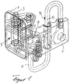
- the motor vehicle door hinge shown in the drawing consists of a first encompassing hinge wing 1 struck on one door arrangement part, not shown in detail in the drawing, and one on the other, in the
- the motor vehicle door hinge shown in the drawing consists of a first encompassing hinge wing 1 attached to one door arrangement part (not shown in detail in the drawing) and a second engaging hinge wing 2 attached to the other door arrangement part, also not shown in the drawing, and a hinge pin 3, over which both hinge wings 1 and 2 are hinged together.
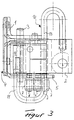
- One encompassing hinge wing 1 is formed in a manner known per se from a folded sheet metal blank and has an abutment support 5 which is oriented approximately transversely to its stop base 4 and on which abutment rollers 7 are rotatably displaced via bearing axes 6.
- the other engaging hinge wing 2 has an approximately L-shaped cross-sectional shape and is rotatably supported by means of its one profile leg 8 via the hinge pin 3 on the hinge wing 1, while its other profile leg 9 is used to fasten it to the door arrangement part.
- a torsion bar spring 10 is mounted in a manner known per se above its sheep part in such a way that its loading arm 11 projects above one hinge wing 1.
- the loading arm 11 engages in a recess 12 of the engaging hinge wing 2 and is therefore limited in its pivotability about the axis 13 of the shaft of the torsion bar spring 10.
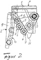
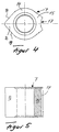
- the abutment rollers 7 are formed uniformly over their entire height and have an essentially heart-shaped cross-sectional shape.
- the abutment rollers 7 have a circular cross-sectional shape in a central region 14 and are equipped with radially directed projections 15 and 16 arranged opposite one another and symmetrical to one another, the radial projection 15 being provided with a latching recess 17 and the other radial projection 16 is smooth wedge-shaped.
- the latching recess 17 in the one radial projection 15 has a contour profile which corresponds to the circular cross-sectional shape of the loading arm 11 of the torsion bar spring 10.
- the locking recesses in the radial projection 15 of the abutment rollers 7 each have a quarter-circular contour, such that the locking recesses 17 are located in the radial projections 15 of two adjacent and mutually pivoted abutment rollers 7 complement each other to a semicircular shape.
- the two flank surfaces 18 and 19 of the smoothly wedge-shaped radial projection 16 of each of the abutment rollers 7 each form an angle of 97 ° with one another, so that due to the fact that the smoothly wedge-shaped projection 16 forms a swiveling end stop for the abutment roller 7, the maximum possible Swivel angle range of adjacent abutment rollers 7 is limited to an angular amount of 97 °.
- the abutment rollers 7 have a uniform profile cross-sectional shape throughout their entire height and are supported on bearing axles 6 which are formed by means of a circumferential knurl 20 by means of rivet pins fixed in a bore recesses in the abutment support 5.
- the bearing axes 6 of the abutment rollers 7 are arranged on the abutment support 5 of the other hinge wing 2 along an arc line which is concentric with the hinge axis.
- the hinge wing 2 containing the abutment support 5 is formed by a folded sheet metal blank and has a rigid opening end stop for the door 21 in the region of its free end.
Landscapes
- Engineering & Computer Science (AREA)
- Mechanical Engineering (AREA)
- Hinge Accessories (AREA)
- Hinges (AREA)
- Closing And Opening Devices For Wings, And Checks For Wings (AREA)
- Power-Operated Mechanisms For Wings (AREA)
- Lock And Its Accessories (AREA)
Applications Claiming Priority (2)
| Application Number | Priority Date | Filing Date | Title |
|---|---|---|---|
| DE19538561 | 1995-10-17 | ||
| DE19538561A DE19538561A1 (de) | 1995-10-17 | 1995-10-17 | Mit einem Türscharnier baulich vereinigter Türfeststeller für Kraftwagentüren |
Publications (3)
| Publication Number | Publication Date |
|---|---|
| EP0769600A2 true EP0769600A2 (fr) | 1997-04-23 |
| EP0769600A3 EP0769600A3 (fr) | 1998-09-16 |
| EP0769600B1 EP0769600B1 (fr) | 2001-02-07 |
Family
ID=7775026
Family Applications (1)
| Application Number | Title | Priority Date | Filing Date |
|---|---|---|---|
| EP96115690A Expired - Lifetime EP0769600B1 (fr) | 1995-10-17 | 1996-10-01 | Charnière de porte pour véhicule à moteur combinée constructivement avec un arrêt de porte |
Country Status (10)
| Country | Link |
|---|---|
| US (1) | US5675869A (fr) |
| EP (1) | EP0769600B1 (fr) |
| CN (1) | CN1080812C (fr) |
| BR (1) | BR9605156A (fr) |
| CZ (1) | CZ290544B6 (fr) |
| DE (2) | DE19538561A1 (fr) |
| ES (1) | ES2155914T3 (fr) |
| MX (1) | MX9604867A (fr) |
| PT (1) | PT769600E (fr) |
| ZA (1) | ZA968676B (fr) |
Cited By (2)
| Publication number | Priority date | Publication date | Assignee | Title |
|---|---|---|---|---|
| FR2804992A1 (fr) | 2000-02-15 | 2001-08-17 | Aries Ind Mecanismes Et Decoup | Ensemble charniere pour porte battante de vehicule automobile |
| FR2811007A1 (fr) | 2000-06-29 | 2002-01-04 | Aries Ind Mecanismes Et Decoup | Charniere avec arret de porte integre |
Families Citing this family (15)
| Publication number | Priority date | Publication date | Assignee | Title |
|---|---|---|---|---|
| US5926917A (en) * | 1998-03-26 | 1999-07-27 | Dura Automotive Systems, Inc. | Door hinge assembly |
| US6105208A (en) * | 1999-04-27 | 2000-08-22 | Midway Products Group, Inc. | Vehicle door check |
| US6148481A (en) * | 1999-07-21 | 2000-11-21 | Chen; Wen Hua | Pivotal device for door and window |
| DE19949647C2 (de) * | 1999-10-14 | 2002-01-31 | Edscha Ag | Türscharnier |
| US6687953B1 (en) | 2000-10-13 | 2004-02-10 | Ventra Group Inc. | Torsion spring door check device |
| GB0111121D0 (en) | 2001-05-05 | 2001-06-27 | Meritor Light Vehicle Sys Ltd | Vehicle, hinge and latching arrangement adjustment method |
| KR20020087502A (ko) * | 2001-05-10 | 2002-11-23 | 현대자동차주식회사 | 자동차용 도어 힌지의 구조 |
| KR20040012179A (ko) * | 2002-08-01 | 2004-02-11 | 기아자동차주식회사 | 베어링을 이용한 자동차용 도어체커 |
| US6938941B2 (en) * | 2003-09-16 | 2005-09-06 | Honda Motor Co., Ltd. | Tailgate dual mode hinge with integrated checker |
| US7257860B2 (en) * | 2003-10-13 | 2007-08-21 | Reell Precision Manufacturing Corporation | Brake mechanism |
| JP4441253B2 (ja) * | 2003-12-25 | 2010-03-31 | 理研化機工業株式会社 | 自動車の製造工程で使用するドア保持装置 |
| DE102004012006B3 (de) * | 2004-03-10 | 2005-06-30 | Ise Innomotive Systems Europe Gmbh | Türscharnier für Kraftfahrzeuge |
| US6976290B2 (en) * | 2004-04-09 | 2005-12-20 | Stahl/Scott Fetzer Company | Hidden hinge for utility vehicle body |
| CN1959051B (zh) * | 2006-09-08 | 2010-06-16 | 王洪波 | 一种车门铰链及其制作方法 |
| US20200270919A1 (en) * | 2019-02-21 | 2020-08-27 | Marathonnorco Aerospace, Inc. | Hold Open Rod Having a Lock Mechanism for Securely Locking the Hold Open Rod in an Extended Configuration |
Citations (1)
| Publication number | Priority date | Publication date | Assignee | Title |
|---|---|---|---|---|
| DE3229766A1 (de) * | 1982-08-10 | 1984-02-16 | Scharwaechter Gmbh Co Kg | Mit einem tuerscharnier baulich vereinigter tuerfeststeller fuer kraftwagentueren |
Family Cites Families (1)
| Publication number | Priority date | Publication date | Assignee | Title |
|---|---|---|---|---|
| US4285098A (en) * | 1979-04-30 | 1981-08-25 | Vought Corporation | Door hinge having torsion bar hold-open structure |
-
1995
- 1995-10-17 DE DE19538561A patent/DE19538561A1/de not_active Withdrawn
-
1996
- 1996-10-01 ES ES96115690T patent/ES2155914T3/es not_active Expired - Lifetime
- 1996-10-01 PT PT96115690T patent/PT769600E/pt unknown
- 1996-10-01 EP EP96115690A patent/EP0769600B1/fr not_active Expired - Lifetime
- 1996-10-01 DE DE59606419T patent/DE59606419D1/de not_active Expired - Lifetime
- 1996-10-14 CZ CZ19963000A patent/CZ290544B6/cs not_active IP Right Cessation
- 1996-10-15 ZA ZA968676A patent/ZA968676B/xx unknown
- 1996-10-16 MX MX9604867A patent/MX9604867A/es unknown
- 1996-10-17 BR BR9605156A patent/BR9605156A/pt not_active IP Right Cessation
- 1996-10-17 US US08/734,371 patent/US5675869A/en not_active Expired - Lifetime
- 1996-10-17 CN CN96120346A patent/CN1080812C/zh not_active Expired - Lifetime
Patent Citations (1)
| Publication number | Priority date | Publication date | Assignee | Title |
|---|---|---|---|---|
| DE3229766A1 (de) * | 1982-08-10 | 1984-02-16 | Scharwaechter Gmbh Co Kg | Mit einem tuerscharnier baulich vereinigter tuerfeststeller fuer kraftwagentueren |
Cited By (3)
| Publication number | Priority date | Publication date | Assignee | Title |
|---|---|---|---|---|
| FR2804992A1 (fr) | 2000-02-15 | 2001-08-17 | Aries Ind Mecanismes Et Decoup | Ensemble charniere pour porte battante de vehicule automobile |
| FR2811007A1 (fr) | 2000-06-29 | 2002-01-04 | Aries Ind Mecanismes Et Decoup | Charniere avec arret de porte integre |
| US6581243B2 (en) * | 2000-06-29 | 2003-06-24 | Oxford Automotive Mecanismes Et Decoupage Fin | Hinge with built-in door stop |
Also Published As
| Publication number | Publication date |
|---|---|
| MX9604867A (es) | 1997-04-30 |
| CN1155482A (zh) | 1997-07-30 |
| US5675869A (en) | 1997-10-14 |
| CZ290544B6 (cs) | 2002-08-14 |
| CZ300096A3 (en) | 1997-05-14 |
| ES2155914T3 (es) | 2001-06-01 |
| ZA968676B (en) | 1997-05-21 |
| EP0769600A3 (fr) | 1998-09-16 |
| EP0769600B1 (fr) | 2001-02-07 |
| DE59606419D1 (de) | 2001-03-15 |
| BR9605156A (pt) | 1998-07-14 |
| PT769600E (pt) | 2001-07-31 |
| CN1080812C (zh) | 2002-03-13 |
| DE19538561A1 (de) | 1997-04-24 |
Similar Documents
| Publication | Publication Date | Title |
|---|---|---|
| EP0769600B1 (fr) | Charnière de porte pour véhicule à moteur combinée constructivement avec un arrêt de porte | |
| DE2430443A1 (de) | Scharnierbaugruppe | |
| EP0791715A1 (fr) | Ensemble de charnière et d'arrêtoir pour portes de véhicule dégondables | |
| DE2308720A1 (de) | Tuerangel mit haltevorrichtung fuer die ofgenstellung | |
| DE3229766C2 (fr) | ||
| DE2727608C2 (fr) | ||
| DE9112079U1 (de) | Betätigungsgetriebe für längsverschiebbare Treibstangen an Beschlägen von Fenstern und Türen o.dgl. | |
| DE69718853T2 (de) | Dekorplatte mit Vorrichtung zum senkrechten Verschieben längs der geschlossenen Tür eines eingebauten Gerätes | |
| DE69405379T2 (de) | Universelles schloss fur pannensichere turen insbesondere fur aufzugsschachturen | |
| DE69123128T2 (de) | Einrichtung für die Bedienung eines Fahrzeugschlosses | |
| EP1103690A1 (fr) | Exutoire de désenfumage | |
| DE2917164C2 (fr) | ||
| DE4221083C2 (de) | Karusselltür | |
| WO1995030974A1 (fr) | Serrure actionnee par des pieces de monnaie | |
| DE29516420U1 (de) | Mit einem Türscharnier baulich vereinigter Türfeststeller für Kraftwagentüren | |
| EP0899402B1 (fr) | Ferrure de verrouillage | |
| DE9316459U1 (de) | Türverriegelung für zweiflügelige Türen, insbesondere für behindertengerechte Toilettentüren in Reisezugwagen | |
| EP0338519A1 (fr) | Charnière à double joint pour la connection d'un panneau de porte à la paroi fixe d'un chassis de voiture utilitaire | |
| EP0426952B1 (fr) | Charnière de porte combinée dans sa construction avec un arrêt de porte | |
| DE29617865U1 (de) | Türfeststeller für Kraftwagentüren | |
| DE9417227U1 (de) | Verriegelungsschloß | |
| EP1068418B1 (fr) | Element d'arret a barre de torsion pour portieres de vehicule automobile | |
| DE2833879C2 (de) | Scharnier mit Halteeinrichtung | |
| DE3110114A1 (de) | Aushaengbares scharnier fuer den seitenladen von fahrzeugen | |
| EP0262347A2 (fr) | Dispositif de maintien en position ouverte d'une porte, d'une fenêtre etc. au moins pivotante |
Legal Events
| Date | Code | Title | Description |
|---|---|---|---|
| PUAI | Public reference made under article 153(3) epc to a published international application that has entered the european phase |
Free format text: ORIGINAL CODE: 0009012 |
|
| 17P | Request for examination filed |
Effective date: 19961001 |
|
| AK | Designated contracting states |
Kind code of ref document: A2 Designated state(s): DE ES FR GB IT NL PT SE |
|
| PUAL | Search report despatched |
Free format text: ORIGINAL CODE: 0009013 |
|
| AK | Designated contracting states |
Kind code of ref document: A3 Designated state(s): DE ES FR GB IT NL PT SE |
|
| GRAG | Despatch of communication of intention to grant |
Free format text: ORIGINAL CODE: EPIDOS AGRA |
|
| GRAG | Despatch of communication of intention to grant |
Free format text: ORIGINAL CODE: EPIDOS AGRA |
|
| GRAH | Despatch of communication of intention to grant a patent |
Free format text: ORIGINAL CODE: EPIDOS IGRA |
|
| 17Q | First examination report despatched |
Effective date: 20000721 |
|
| RAP1 | Party data changed (applicant data changed or rights of an application transferred) |
Owner name: ED. SCHARWAECHTER GMBH |
|
| GRAH | Despatch of communication of intention to grant a patent |
Free format text: ORIGINAL CODE: EPIDOS IGRA |
|
| GRAA | (expected) grant |
Free format text: ORIGINAL CODE: 0009210 |
|
| AK | Designated contracting states |
Kind code of ref document: B1 Designated state(s): DE ES FR GB IT NL PT SE |
|
| REF | Corresponds to: |
Ref document number: 59606419 Country of ref document: DE Date of ref document: 20010315 |
|
| ITF | It: translation for a ep patent filed | ||
| GBT | Gb: translation of ep patent filed (gb section 77(6)(a)/1977) |
Effective date: 20010410 |
|
| ET | Fr: translation filed | ||
| REG | Reference to a national code |
Ref country code: ES Ref legal event code: FG2A Ref document number: 2155914 Country of ref document: ES Kind code of ref document: T3 |
|
| REG | Reference to a national code |
Ref country code: PT Ref legal event code: SC4A Free format text: AVAILABILITY OF NATIONAL TRANSLATION Effective date: 20010427 |
|
| PLBE | No opposition filed within time limit |
Free format text: ORIGINAL CODE: 0009261 |
|
| STAA | Information on the status of an ep patent application or granted ep patent |
Free format text: STATUS: NO OPPOSITION FILED WITHIN TIME LIMIT |
|
| REG | Reference to a national code |
Ref country code: GB Ref legal event code: IF02 |
|
| 26N | No opposition filed | ||
| PGFP | Annual fee paid to national office [announced via postgrant information from national office to epo] |
Ref country code: PT Payment date: 20020923 Year of fee payment: 7 |
|
| PGFP | Annual fee paid to national office [announced via postgrant information from national office to epo] |
Ref country code: GB Payment date: 20020925 Year of fee payment: 7 |
|
| PGFP | Annual fee paid to national office [announced via postgrant information from national office to epo] |
Ref country code: NL Payment date: 20020930 Year of fee payment: 7 |
|
| PGFP | Annual fee paid to national office [announced via postgrant information from national office to epo] |
Ref country code: SE Payment date: 20021002 Year of fee payment: 7 |
|
| PGFP | Annual fee paid to national office [announced via postgrant information from national office to epo] |
Ref country code: FR Payment date: 20021009 Year of fee payment: 7 |
|
| PGFP | Annual fee paid to national office [announced via postgrant information from national office to epo] |
Ref country code: ES Payment date: 20021022 Year of fee payment: 7 |
|
| PG25 | Lapsed in a contracting state [announced via postgrant information from national office to epo] |
Ref country code: GB Free format text: LAPSE BECAUSE OF NON-PAYMENT OF DUE FEES Effective date: 20031001 |
|
| PG25 | Lapsed in a contracting state [announced via postgrant information from national office to epo] |
Ref country code: SE Free format text: LAPSE BECAUSE OF NON-PAYMENT OF DUE FEES Effective date: 20031002 Ref country code: ES Free format text: LAPSE BECAUSE OF NON-PAYMENT OF DUE FEES Effective date: 20031002 |
|
| PG25 | Lapsed in a contracting state [announced via postgrant information from national office to epo] |
Ref country code: PT Free format text: LAPSE BECAUSE OF NON-PAYMENT OF DUE FEES Effective date: 20040430 |
|
| PG25 | Lapsed in a contracting state [announced via postgrant information from national office to epo] |
Ref country code: NL Free format text: LAPSE BECAUSE OF NON-PAYMENT OF DUE FEES Effective date: 20040501 |
|
| GBPC | Gb: european patent ceased through non-payment of renewal fee |
Effective date: 20031001 |
|
| EUG | Se: european patent has lapsed | ||
| PG25 | Lapsed in a contracting state [announced via postgrant information from national office to epo] |
Ref country code: FR Free format text: LAPSE BECAUSE OF NON-PAYMENT OF DUE FEES Effective date: 20040630 |
|
| NLV4 | Nl: lapsed or anulled due to non-payment of the annual fee |
Effective date: 20040501 |
|
| REG | Reference to a national code |
Ref country code: FR Ref legal event code: ST Ref country code: PT Ref legal event code: MM4A Free format text: LAPSE DUE TO NON-PAYMENT OF FEES Effective date: 20040430 |
|
| PG25 | Lapsed in a contracting state [announced via postgrant information from national office to epo] |
Ref country code: IT Free format text: LAPSE BECAUSE OF NON-PAYMENT OF DUE FEES Effective date: 20051001 |
|
| REG | Reference to a national code |
Ref country code: ES Ref legal event code: FD2A Effective date: 20031002 |
|
| REG | Reference to a national code |
Ref country code: DE Ref legal event code: R082 Ref document number: 59606419 Country of ref document: DE Representative=s name: BONNEKAMP & SPARING, DE Effective date: 20110812 Ref country code: DE Ref legal event code: R081 Ref document number: 59606419 Country of ref document: DE Owner name: EDSCHA ENGINEERING GMBH, DE Free format text: FORMER OWNER: ED. SCHARWAECHTER GMBH, 42855 REMSCHEID, DE Effective date: 20110812 |
|
| PGFP | Annual fee paid to national office [announced via postgrant information from national office to epo] |
Ref country code: DE Payment date: 20151022 Year of fee payment: 20 |
|
| REG | Reference to a national code |
Ref country code: DE Ref legal event code: R071 Ref document number: 59606419 Country of ref document: DE |