EP0769332B1 - Einrichtung für den Transport von flachen Produkten - Google Patents
Einrichtung für den Transport von flachen Produkten Download PDFInfo
- Publication number
- EP0769332B1 EP0769332B1 EP96810679A EP96810679A EP0769332B1 EP 0769332 B1 EP0769332 B1 EP 0769332B1 EP 96810679 A EP96810679 A EP 96810679A EP 96810679 A EP96810679 A EP 96810679A EP 0769332 B1 EP0769332 B1 EP 0769332B1
- Authority
- EP
- European Patent Office
- Prior art keywords
- conveyor
- transport
- products
- transport containers
- guide
- Prior art date
- Legal status (The legal status is an assumption and is not a legal conclusion. Google has not performed a legal analysis and makes no representation as to the accuracy of the status listed.)
- Expired - Lifetime
Links
Images

Classifications
-
- B—PERFORMING OPERATIONS; TRANSPORTING
- B07—SEPARATING SOLIDS FROM SOLIDS; SORTING
- B07C—POSTAL SORTING; SORTING INDIVIDUAL ARTICLES, OR BULK MATERIAL FIT TO BE SORTED PIECE-MEAL, e.g. BY PICKING
- B07C3/00—Sorting according to destination
- B07C3/02—Apparatus characterised by the means used for distribution
- B07C3/08—Apparatus characterised by the means used for distribution using arrangements of conveyors
- B07C3/082—In which the objects are carried by transport holders and the transport holders form part of the conveyor belts
-
- B—PERFORMING OPERATIONS; TRANSPORTING
- B65—CONVEYING; PACKING; STORING; HANDLING THIN OR FILAMENTARY MATERIAL
- B65H—HANDLING THIN OR FILAMENTARY MATERIAL, e.g. SHEETS, WEBS, CABLES
- B65H2404/00—Parts for transporting or guiding the handled material
- B65H2404/30—Chains
- B65H2404/31—Chains with auxiliary handling means
- B65H2404/312—Pockets, containers
-
- B—PERFORMING OPERATIONS; TRANSPORTING
- B65—CONVEYING; PACKING; STORING; HANDLING THIN OR FILAMENTARY MATERIAL
- B65H—HANDLING THIN OR FILAMENTARY MATERIAL, e.g. SHEETS, WEBS, CABLES
- B65H2405/00—Parts for holding the handled material
- B65H2405/20—Cassettes, holders, bins, decks, trays, supports or magazines for sheets stacked on edge
- B65H2405/22—Cassettes, holders, bins, decks, trays, supports or magazines for sheets stacked on edge pocket like holder
Definitions
- the invention relates to a device for the transport of flat products according to the preamble of claim 1.
- Such facilities are also used as distribution promoters at the Post or used at warehouses where that is a collection point distribute incoming products to remote locations are.
- Devices of the type described at the beginning are, for example in post offices to sort mailers by theirs Shipping addresses used.
- the shipping bags are created after the shipping address has been recorded fed to a feeder, who the the shipping bags Transport containers passes which a specific delivery point are assigned in a controlled manner.
- US - A - 3,915,293 discloses an arrangement of the type mentioned above for the transport of flat Products.
- the indirect loading method proposed there of the products via an intermediate conveyor formed waiting room is less productive due to the emergence Processing times when sending letters are not acceptable.
- EP-A-0 638 501 discloses a generic device for the further transport of individually fed flat Products in which the transport container is facing upwards Entry opening for those supported by a feeder Products.
- the object of the invention is therefore to provide a device to create the kind of high output initially mentioned, with which the products on the loading path the Reach the transport container in the correct position.
- the guide elements move in the direction of movement of the products narrowed like a funnel are, so that through the initially wide management the products Reach the management bodies safely and on the subsequent one Can be put on a narrow trajectory.
- the transfer route can be optimized or extended at the transfer point.
- the traction means on which the transport container are attached formed by laterally spaced conveyor chains, that circulate endlessly around pulleys.
- Transport chains are particularly suitable for fastening the guide elements through their side walls on the running axes of the chain links.
- FIG. 1 shows a conveyor device 1 which has transport containers 3 fastened to a traction means formed from endlessly rotating conveyor chains 2. This is provided at its upper end facing a feeder 4 with an inlet opening 5 through which a flat product 6 is conveyed or falls from the feeder 4 into the transport container 3.
- the products 6 are mailing bags, parcels, printed products or workpieces that are distributed from one collection point to different, distant locations, storage or work places, or transported to other collection points.
- the transport containers 3, which are attached to the traction means at regular intervals, have an inclined position counter to the conveying direction F of the conveying device 1 (to the rear), so that the length of the loading path of a transport container in the conveying direction F can be optimized despite the compact arrangement.
- a proposed feeder 4 which passes on the incoming products 6 to the conveyor device 1 in time, consists of a linear conveyor 7 engaging in a flat frictional engagement on the one main surface of the products 6 for transferring the products 6 to the transport containers 3 and one by one perpendicular to the Conveying direction of the linear conveyor 7 directed axis driven conveyor rotor 8, which rolls with a rolling area of its peripheral surface frictionally on the other main surface of a product 6 when transferred.
- the feeder 4 is driven by a motor 9, which is connected by a gear 10 to a conveyor belt designed as a linear conveyor 7 and the conveyor rotor 8.
- a biasing device 11 ensures the correct contact pressure of the conveyor rotor 8 product 6.
- the present device provides a guide arrangement 12 which laterally limits the conveying path of the products 6.
- This guide arrangement 12 consists of a pulling member 13 which is driven above the transport container 3 in the same direction as the direction of conveyance F of the conveying device, formed from two parallel transport chains 14, on which individual guide members 15 are arranged at a distance from the transport containers 3 fastened to the traction means of the conveying device 1, which guide the Trajectory resp. enforce the conveyance route of a product 6.
- Conveyor chains 2 and transport chains 14 each have parallel runs which form a transfer section in one section.
- the guide members 15 are funnel-shaped and aligned with the trajectory of a product 6, that is to say the access opening 16 has an extension relative to the entry opening 5 of the transport containers 3, viewed in the conveying direction F, which facilitates the grasping of the products 6 and, through the subsequent tapering, the trajectory of one Product 6 specified.
- the guide member 15 is provided at the downstream end with a guide surface 18 designed as a slide.
- the partially dissolved funnel shape of the guide member 15 is approximately restored due to the lid opening in this area through the lid 17.
- a sliding cover would make these arrangements avoidable.
- the position of the guide surface 18 on the guide member 15 is selected such that the downstream end of the chute is in contact with the inner wall 19 of the transport container 3 rearward in the conveying direction F, in any case does not form a disruptive step or the inlet opening 5 of the transport container 3 is disadvantageous reduced.
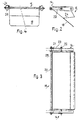
- FIG. 2 shows the funnel-shaped guide member 15 in the loading position. It is fastened in each case by a connecting rod 20 in one pivot axis 21 and in the other pivot axis 22 of a chain link 23, so that the transport chains 14 are not restricted in terms of the mobility of their chain links.
- a bar 25 is provided on the side walls 24 of the guide member 15.
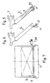
- 5 to 7 illustrate the formation of a transport container 3 in the emptying position.
- 5 shows the still closed transport container 3, which has changed its position by approximately 180 ° with respect to the loading position.
- the product 6 is now near the lid and leaves the transport container 3 as soon as the lid 17 is opened (see FIG. 6).
- the lid 17 is held by a locking device 26, the bolt 27 of which is lifted out of the locking means at the right time by an unlocking device 28 according to FIG. 7.
- the pivoting of the lid 17 to open a transport container 3 is carried out by a torsion spring (not shown).
- the cover 17 is closed again against the force of the torsion spring.
Landscapes
- Discharge Of Articles From Conveyors (AREA)
- Packaging Of Special Articles (AREA)
- Control And Other Processes For Unpacking Of Materials (AREA)
- Framework For Endless Conveyors (AREA)
- Attitude Control For Articles On Conveyors (AREA)
- Chain Conveyers (AREA)
- Specific Conveyance Elements (AREA)
Description
- Fig. 1
- eine Seitenansicht der erfindungsgemässen Einrichtung,
- Fig. 2
- eine ausschnittweise Seitenansicht der Führungsanordnung im Bereich eines Führungsorgans,
- Fig. 3
- eine Seitenansicht gemäss Fig. 2,
- Fig. 4
- eine Draufsicht auf Fig. 2
- Fig. 5
- eine Seitenansicht eines geschlossenen Transportbehälters in der Transportlage,
- Fig. 6
- eine Seitenansicht eines offenen Transportbehälters in der Entleerungslage und
- Fig. 7
- eine Ansicht des offenen Transportbehälters in Förderrichtung.
Ein vorgeschlagener Beschicker 4, der die ankommenden Produkte 6 im Takt der Fördervorrichtung 1 an diese weitergibt, besteht aus einem in flächigem Reibschluss an der einen Hauptfläche der Produkte 6 angreifenden Linearförderer 7 zum Übergeben der Produkte 6 an die Transportbehälter 3 und einem um eine senkrecht zur Förderrichtung des Linearförderers 7 gerichtete Achse angetriebenen Förderrotor 8, der sich beim Übergeben mit einem Abrollbereich seiner Umfangsfläche reibschlüssig auf der anderen Hauptfläche eines Produktes 6 abrollt. Der Antrieb des Beschickers 4 erfolgt durch einen Motor 9, der durch ein Getriebe 10 mit einem als Linearförderer 7 ausgebildeteten Förderband und dem Förderrotor 8 verbunden ist. Eine Vorspanneinrichtung 11 sorgt für den richtigen Anpressdruck des Förderrotors 8 Produkt 6.
Die Führungsorgane 15 sind trichterförmig ausgebildet und nach der Flugbahn eines Produktes 6 ausgerichtet, d.h. die Zutrittsöffnung 16 weist gegenüber der Eintrittsöffnung 5 der Transportbehälter 3 in Förderrichtung F betrachtet eine Erweiterung auf, die das Erfassen der Produkte 6 erleichtert und durch die anschliessende Verjüngung die Flugbahn eines Produktes 6 präzisiert.
Im vorliegenden Fall, wo die Eintrittsöffnung 5 der Transportbehälter 3 mit einem klappenartigen Deckel 17 versehen sind, der im offenen Zustand einen Führungsanteil bildet, ist das Führungsorgan 15 am stromabwärts gerichteten Ende mit einer als Rutsche ausgebildeten Leitfläche 18 versehen. Die teilweise aufgelöste Trichterform des Führungsorgans 15 wird aufgrund der Deckelöffnung in diesem Bereich durch den Deckel 17 annähernd wiederhergestellt.
Ein Schiebedeckel würde diese Vorkehrungen umgehbar machen. Die Lage der Leitfläche 18 ist an dem Führungsorgan 15 so gewählt, dass das stromabwärts liegende Ende der Rutsche während der Beschickung an der in Förderrichtung F rückwärtigen Innenwand 19 des Transportbehälters 3 etwa ansteht, jedenfalls keinen störenden Absatz bildet oder die Eintrittsöffnung 5 des Transportbehälters 3 nachteilig verkleinert.
Fig. 2 zeigt das trichterförmige Führungsorgan 15 in der Beschickungslage. Es ist jeweils durch eine Verbindungsstange 20 in der einen Schwenkachse 21 und in der anderen Schwenkachse 22 eines Kettengliedes 23 befestigt, so dass die Transportketten 14 keine Einschränkung bezüglich Beweglichkeit ihrer Kettenglieder erfahren. Zur Verstärkung der Verbindung mit der Transportkette 14 ist jeweils eine an den Seitenwänden 24 des Führungsorgans 15 befestigte Leiste 25 vorgesehen.
Gegen die Kraft der Drehfeder wird der Deckel 17 wieder geschlossen.
- 1
- Fördervorrichtung
- 2
- Förderkette
- 3
- Transportbehälter
- 4
- Beschicker
- 5
- Eintrittsöffnung
- 6
- Produkt
- 7
- Linearförder
- 8
- Förderrotor
- 9
- Motor
- 10
- Getriebe
- 11
- Vorspanneinrichtung
- 12
- Führungsanordnung
- 13
- Zugorgan
- 14
- Transportkette
- 15
- Führungsorgan
- 16
- Zutrittsöffnung
- 17
- klappenartiger Deckel
- 18
- Leitfläche
- 19
- rückwärtige Innenwand
- 20
- Verbindungsstange
- 21
- erste Schwenkachse
- 22
- zweite Schwenkachse
- 23
- Kettenglied
- 24
- Seitenwand
- 25
- Leiste
- 26
- Verriegelungsvorrichtung
- 27
- Riegel
- 28
- Entriegelungsvorrichtung
- F
- Förderrichtung
- R
- Umlaufrichtung des die Führungsanordnung 12 enthaltenden Zugorgans 13
Claims (11)
- Einrichtung für den Transport von flachen Produkten (6), die jeweils durch einen Beschicker (4) den an einem angetriebenen Zugmittel (13, 14) einer Fördervorrichtung (1) befestigten, eine dem darüber angeordneten einen Linearförderer (7) aufweisenden Beschicker (4) zugewendete Eintrittsöffnung (5) aufweisenden Transportbehältern (3) zugeführt werden,
dadurch gekennzeichnet, dass die Produkte (6) mittels des Linearförderers (7) in Richtung der Transportbehälter (3) bewegt werden und dass oberhalb der Fördervorrichtung (1) eine gleichsinnig zur Förderrichtung (F) und etwa parallel zu den Eintrittsöffnungen (5) der Transportbehälter (3) verlaufende, die Flugbahn der Produkte (6) durchsetzende, aus mehreren an einem endlos umlaufenden Zugorgan (13) befestigten Führungsorganen (15) gebildete Führungsanordnung (12) vorgesehen ist. - Einrichtung nach Anspruch 1,
dadurch gekennzeichnet, dass die Führungsorgane (15) sich in Bewegungsrichtung der Produkte (6) trichterförmig verengend ausgebildet sind. - Einrichtung nach Anspruch 1 oder 2,
dadurch gekennzeichnet, dass die Führungsorgane (15) nach den regelmässigen Abständen der sich folgenden Transportbehälter (3) an dem Zugorgan (13) befestigt und taktgleich mit den Transportbehälern (3) angetrieben sind. - Einrichtung nach Anspruch 3,
dadurch gekennzeichnet, dass die Transportbehälter(3) eine der Förderrichtung der Fördervorrichtung (1) entgegengesetzt geneigte Lage aufweisen. - Einrichtung nach Anspruch 4,
dadurch gekennzeichnet, dass die Führungsorgane (15) am stromabwärts liegenden Ende mit einer als Rutsche ausgebildeten Leitfläche (18) versehen sind. - Einrichtung nach einem der Ansprüche 1 bis 5
dadurch gekennzeichnet, dass das Zugorgan (13) durch seitlich beabstandete Transportketten (14) gebildet ist. - Einrichtung nach Anspruch 6,
dadurch gekennzeichnet, dass die zwischen den Transportketten (14) angeordneten Führungsorgane (15) durch seitliche Wände (24) mit den Laufachsen der Kettenglieder (23) verbunden sind. - Einrichtung nach einem der Ansprüche 1 bis 7,
dadurch gekennzeichnet, dass die Transportbehälter (3) allseits geschlossen ausgebildet sind und an der Einstrittsöffnung (5) einen klappen- oder schieberartigen Deckel (17) aufweisen. - Einrichtung nach einem der Ansprüche 5 bis 8,
dadurch gekennzeichnet, dass das stromabwärts liegende Ende der Rutsche während der Beschickung an der in Förderrichtung rückwärtigen Innenwand (19) des Transportbehälters (3) wenigstens annähernd ansteht. - Einrichtung nach Anspruch 8, bei der der Transportbehälter (3) einen klappenartigen Deckel (17) aufweist,
dadurch gekennzeichnet, dass der Deckel (17) durch Federkraft in die Offenstellung versetzt und durch eine Steuerkurve geschlossen wird. - Einrichtung nach einem der Ansprüche 1 bis 10,
dadurch gekennzeichnet, dass die Führungsanordnung (12) wenigstens im Beschickungsbereich eine seitliche Transportkettenführung (28) aufweist.
Applications Claiming Priority (3)
| Application Number | Priority Date | Filing Date | Title |
|---|---|---|---|
| CH2942/95 | 1995-10-17 | ||
| CH294295 | 1995-10-17 | ||
| CH294295 | 1995-10-17 |
Publications (2)
| Publication Number | Publication Date |
|---|---|
| EP0769332A1 EP0769332A1 (de) | 1997-04-23 |
| EP0769332B1 true EP0769332B1 (de) | 2002-03-20 |
Family
ID=4245103
Family Applications (1)
| Application Number | Title | Priority Date | Filing Date |
|---|---|---|---|
| EP96810679A Expired - Lifetime EP0769332B1 (de) | 1995-10-17 | 1996-10-11 | Einrichtung für den Transport von flachen Produkten |
Country Status (6)
| Country | Link |
|---|---|
| US (1) | US5819909A (de) |
| EP (1) | EP0769332B1 (de) |
| JP (1) | JP3974960B2 (de) |
| AT (1) | ATE214645T1 (de) |
| AU (1) | AU718119B2 (de) |
| DE (1) | DE59608910D1 (de) |
Families Citing this family (1)
| Publication number | Priority date | Publication date | Assignee | Title |
|---|---|---|---|---|
| EP1812174A1 (de) * | 2004-11-02 | 2007-08-01 | Siemens Aktiengesellschaft | System und verfahren zum laden von postartikeln auf eine übergabeeinheit |
Family Cites Families (5)
| Publication number | Priority date | Publication date | Assignee | Title |
|---|---|---|---|---|
| DE1296099B (de) * | 1967-08-31 | 1969-05-22 | Siemens Ag | Anordnung zur Zwischenstapelung von Belegen |
| DE2207135C3 (de) * | 1972-02-16 | 1982-02-18 | Paul Hettich & Co, 4983 Kirchlengern | Speicherträger zum Aufnehmen von Möbelscharnieren |
| US3915293A (en) * | 1974-02-15 | 1975-10-28 | Fairchild Industries | Article loading apparatus |
| DE3144355C2 (de) * | 1981-11-07 | 1985-12-12 | Du Pont de Nemours (Deutschland) GmbH, 4000 Düsseldorf | Vorrichtung zum Fördern von flachen, an mindestens einer Oberfläche vorbehandelten Werkstücken durch eine Behandlungsstation |
| EP0638501B1 (de) * | 1993-08-10 | 1996-12-18 | Grapha-Holding Ag | Fördereinrichtung für den Weitertransport von einzeln zugeführten flachen Produkten |
-
1996
- 1996-10-11 EP EP96810679A patent/EP0769332B1/de not_active Expired - Lifetime
- 1996-10-11 DE DE59608910T patent/DE59608910D1/de not_active Expired - Fee Related
- 1996-10-11 AU AU68195/96A patent/AU718119B2/en not_active Ceased
- 1996-10-11 JP JP27023696A patent/JP3974960B2/ja not_active Expired - Fee Related
- 1996-10-11 AT AT96810679T patent/ATE214645T1/de not_active IP Right Cessation
- 1996-10-16 US US08/732,996 patent/US5819909A/en not_active Expired - Fee Related
Also Published As
| Publication number | Publication date |
|---|---|
| AU6819596A (en) | 1997-04-24 |
| JP3974960B2 (ja) | 2007-09-12 |
| EP0769332A1 (de) | 1997-04-23 |
| US5819909A (en) | 1998-10-13 |
| ATE214645T1 (de) | 2002-04-15 |
| DE59608910D1 (de) | 2002-04-25 |
| JPH09165008A (ja) | 1997-06-24 |
| AU718119B2 (en) | 2000-04-06 |
Similar Documents
| Publication | Publication Date | Title |
|---|---|---|
| DE19609633B4 (de) | Vorrichtung zum Fördern von Gegenständen | |
| DE2814686C2 (de) | Fördervorrichtung | |
| DE60200936T2 (de) | Vertikalumlenkeinrichtung | |
| EP0638501B1 (de) | Fördereinrichtung für den Weitertransport von einzeln zugeführten flachen Produkten | |
| EP2921435B1 (de) | Umlenkvorrichtung für Gegenstände und Verfahren zum Umlenken von Gegenständen | |
| DE102008008009A1 (de) | Fördereinrichtung zum vertikalen Transport von Stückgut | |
| DE3529071C2 (de) | Vorrichtung zum Stapeln von Packungseinheiten | |
| EP0885821A1 (de) | Vorrichtung zum Ausrichten von im Grundriss annähernd rechteckigen Produkten | |
| EP0059984B1 (de) | Ausschleusvorrichtung für eine Förderbahn | |
| DE102016102944A1 (de) | Leergut-Sortiereinrichtung und Leergut-Rücknahmesystem | |
| DE3806168A1 (de) | Foerdereinrichtung fuer gegenstaende | |
| DE69618520T2 (de) | Umlenkvorrichtung zum Transport von Produkten, insbesondere von graphischen Produkten oder Verlagsprodukten | |
| DE2752193C2 (de) | Transportvorrichtung für Serienerzeugnisse innerhalb einer Wägevorrichtung | |
| CH682911A5 (de) | Verfahren zum Herstellen vom mehrteiligen Druckereierzeugnissen, nach diesem Verfahren hergestelltes Druckereierzeugnis und Vorrichtung zur Durchführung des Verfahrens. | |
| DE3724839C2 (de) | ||
| DE2858724C2 (de) | ||
| EP0478911A1 (de) | Vorrichtung zum wahlweisen Überführen von Erzeugnissen aus einer entlang eines ersten Förderweges transportierten Schuppenformation auf einen zweiten Förderweg | |
| EP0100494B1 (de) | Vorrichtung zur Zuführung von Zigaretten oder dgl. zu einer Verpackungsmaschine | |
| EP0799780A2 (de) | Palettiervorrichtung für Riespakete | |
| DE3401307A1 (de) | Transportvorrichtung zur verwendung in einer maschine zum verarbeiten von geschaeftsformularen sowie verfahren zum ueberlappen von geschaeftsformularen | |
| DD211095A5 (de) | Einrichtung zum foerdern und abgeben von fischen | |
| EP0850111B1 (de) | Sortiereinrichtung, insbesondere für postgut | |
| DE10110787A1 (de) | Verfahren und Vorrichtung zum Verpacken von länglichen Gegenständen | |
| EP0769332A1 (de) | Einrichtung für den Transport von flachen Produkten | |
| DE4211682A1 (de) | Verfahren und Vorrichtung zur Beschickung und Entleerung eines Stapelgleises |
Legal Events
| Date | Code | Title | Description |
|---|---|---|---|
| PUAI | Public reference made under article 153(3) epc to a published international application that has entered the european phase |
Free format text: ORIGINAL CODE: 0009012 |
|
| AK | Designated contracting states |
Kind code of ref document: A1 Designated state(s): AT CH DE DK FR GB IT LI NL |
|
| 17P | Request for examination filed |
Effective date: 19970908 |
|
| 17Q | First examination report despatched |
Effective date: 19991116 |
|
| RAP1 | Party data changed (applicant data changed or rights of an application transferred) |
Owner name: SIEMENS AKTIENGESELLSCHAFT |
|
| GRAG | Despatch of communication of intention to grant |
Free format text: ORIGINAL CODE: EPIDOS AGRA |
|
| GRAG | Despatch of communication of intention to grant |
Free format text: ORIGINAL CODE: EPIDOS AGRA |
|
| GRAH | Despatch of communication of intention to grant a patent |
Free format text: ORIGINAL CODE: EPIDOS IGRA |
|
| GRAH | Despatch of communication of intention to grant a patent |
Free format text: ORIGINAL CODE: EPIDOS IGRA |
|
| REG | Reference to a national code |
Ref country code: GB Ref legal event code: IF02 |
|
| GRAA | (expected) grant |
Free format text: ORIGINAL CODE: 0009210 |
|
| AK | Designated contracting states |
Kind code of ref document: B1 Designated state(s): AT CH DE DK FR GB IT LI NL |
|
| PG25 | Lapsed in a contracting state [announced via postgrant information from national office to epo] |
Ref country code: NL Free format text: LAPSE BECAUSE OF FAILURE TO SUBMIT A TRANSLATION OF THE DESCRIPTION OR TO PAY THE FEE WITHIN THE PRESCRIBED TIME-LIMIT Effective date: 20020320 |
|
| REF | Corresponds to: |
Ref document number: 214645 Country of ref document: AT Date of ref document: 20020415 Kind code of ref document: T |
|
| REG | Reference to a national code |
Ref country code: CH Ref legal event code: EP |
|
| GBT | Gb: translation of ep patent filed (gb section 77(6)(a)/1977) |
Effective date: 20020320 |
|
| REF | Corresponds to: |
Ref document number: 59608910 Country of ref document: DE Date of ref document: 20020425 |
|
| PG25 | Lapsed in a contracting state [announced via postgrant information from national office to epo] |
Ref country code: DK Free format text: LAPSE BECAUSE OF FAILURE TO SUBMIT A TRANSLATION OF THE DESCRIPTION OR TO PAY THE FEE WITHIN THE PRESCRIBED TIME-LIMIT Effective date: 20020620 |
|
| ET | Fr: translation filed | ||
| NLV1 | Nl: lapsed or annulled due to failure to fulfill the requirements of art. 29p and 29m of the patents act | ||
| PG25 | Lapsed in a contracting state [announced via postgrant information from national office to epo] |
Ref country code: AT Free format text: LAPSE BECAUSE OF NON-PAYMENT OF DUE FEES Effective date: 20021011 |
|
| PGFP | Annual fee paid to national office [announced via postgrant information from national office to epo] |
Ref country code: CH Payment date: 20030115 Year of fee payment: 7 |
|
| PLBE | No opposition filed within time limit |
Free format text: ORIGINAL CODE: 0009261 |
|
| STAA | Information on the status of an ep patent application or granted ep patent |
Free format text: STATUS: NO OPPOSITION FILED WITHIN TIME LIMIT |
|
| 26N | No opposition filed |
Effective date: 20021223 |
|
| PG25 | Lapsed in a contracting state [announced via postgrant information from national office to epo] |
Ref country code: LI Free format text: LAPSE BECAUSE OF NON-PAYMENT OF DUE FEES Effective date: 20031031 Ref country code: CH Free format text: LAPSE BECAUSE OF NON-PAYMENT OF DUE FEES Effective date: 20031031 |
|
| REG | Reference to a national code |
Ref country code: CH Ref legal event code: PL |
|
| PGFP | Annual fee paid to national office [announced via postgrant information from national office to epo] |
Ref country code: IT Payment date: 20081028 Year of fee payment: 13 |
|
| PGFP | Annual fee paid to national office [announced via postgrant information from national office to epo] |
Ref country code: FR Payment date: 20081017 Year of fee payment: 13 |
|
| PGFP | Annual fee paid to national office [announced via postgrant information from national office to epo] |
Ref country code: DE Payment date: 20081218 Year of fee payment: 13 |
|
| PGFP | Annual fee paid to national office [announced via postgrant information from national office to epo] |
Ref country code: GB Payment date: 20091019 Year of fee payment: 14 |
|
| REG | Reference to a national code |
Ref country code: FR Ref legal event code: ST Effective date: 20100630 |
|
| PG25 | Lapsed in a contracting state [announced via postgrant information from national office to epo] |
Ref country code: FR Free format text: LAPSE BECAUSE OF NON-PAYMENT OF DUE FEES Effective date: 20091102 Ref country code: DE Free format text: LAPSE BECAUSE OF NON-PAYMENT OF DUE FEES Effective date: 20100501 |
|
| PG25 | Lapsed in a contracting state [announced via postgrant information from national office to epo] |
Ref country code: IT Free format text: LAPSE BECAUSE OF NON-PAYMENT OF DUE FEES Effective date: 20091011 |
|
| GBPC | Gb: european patent ceased through non-payment of renewal fee |
Effective date: 20101011 |
|
| PG25 | Lapsed in a contracting state [announced via postgrant information from national office to epo] |
Ref country code: GB Free format text: LAPSE BECAUSE OF NON-PAYMENT OF DUE FEES Effective date: 20101011 |