EP0768741B1 - Transportable Raumzelle als Umspannstation - Google Patents
Transportable Raumzelle als Umspannstation Download PDFInfo
- Publication number
- EP0768741B1 EP0768741B1 EP96115760A EP96115760A EP0768741B1 EP 0768741 B1 EP0768741 B1 EP 0768741B1 EP 96115760 A EP96115760 A EP 96115760A EP 96115760 A EP96115760 A EP 96115760A EP 0768741 B1 EP0768741 B1 EP 0768741B1
- Authority
- EP
- European Patent Office
- Prior art keywords
- room
- cell according
- wall
- cover
- section
- Prior art date
- Legal status (The legal status is an assumption and is not a legal conclusion. Google has not performed a legal analysis and makes no representation as to the accuracy of the status listed.)
- Expired - Lifetime
Links
Images


Classifications
-
- H—ELECTRICITY
- H02—GENERATION; CONVERSION OR DISTRIBUTION OF ELECTRIC POWER
- H02B—BOARDS, SUBSTATIONS OR SWITCHING ARRANGEMENTS FOR THE SUPPLY OR DISTRIBUTION OF ELECTRIC POWER
- H02B7/00—Enclosed substations, e.g. compact substations
- H02B7/06—Distribution substations, e.g. for urban network
Definitions
- the invention relates to a transportable room cell in the form one partially submerged in the ground, an interior for a transformer, for high, medium and / or low voltage switchgear or the like.
- Containing plant parts Substation with four wall parts, which may be monolithic connected to a base plate - i.e. to this molded - are, as well as with a roof from both sides of a cross-station interior arranged upward opening gutter support and separated pivotable about parallel joints Lids.
- DE-A-24 01 532 discloses a walk-in medium voltage network station from prefabricated parts, in which several among each other same elements each L-shaped cross section a hood-shaped roof made of glass fiber reinforced plastic or made of corrosion-resistant steel or aluminum sheet form; the elements are on one - also as a rain gutter serving - U-beam articulated on both sides, the is supported on the end walls of the station.
- the vertical apron sections of the elements are provided with stiffening ribs vertically provided between them incorporated slots and with locking elements equipped and rely on the appropriate From the top of the wall. It is also for better ventilation due to an overlapping overhang of the roof element on the An air gap is provided on the base of the station.
- the entry is for elements that are folded up in pairs via a swing ladder or changing the units possible.
- the interior of the cell for example, from scripture to DE-U-83 34 221 known substation of this type into a transformer room to receive the transformer oil pan underneath as well as a switch room for receiving of those high, medium or low voltage switchgear divided up.
- Such stations are called so-called finishing stations in the factory with the necessary switching devices - with Except for the transformer, mounting rails and the complete electrical installation including earthing, so that only the usual at the construction site wheel-mounted transformer on existing ones in the station Rails are inserted into the cell interior got to.
- the latter can be swiveled horizontally thanks to two Accessible doors that are part of a profile and panels existing side wall.
- DE-A-31 10 304 discloses a room cell as electrical Network station, the lower side walls and one on them has overlying intermediate floor. Extends from the mezzanine a partition wall upwards as a pressure sign, the at a predetermined distance into the interior of the network station pulled in and just under the roof plate of the Station is guided.
- EP-B-196 624 So-called small stations that are not accessible are EP-B-196 624 can be seen with an i. w. on the ground surface or Ground-level concrete floor pan, on which one Housing body made of a rod frame for cast infills, doors or the like.
- the inventor was aware of this state of the art set the goal of such a small station on simple and inexpensive way to manufacture, equip as well as use.
- the adaptability to different Types of electrical installation elements facilitated and operational safety can be increased.
- the roof consists of two - separately around the parallel joints - swiveling Lids, one with a ridge section on one of the cell interior overlapping, upwardly opening gutter supports and one from the level of the ridge section of the lid has angled apron portion; the latter forms the substation in the closed state upper part of a wall part, in particular on the Front wall, the lid edge and the subsequent lid limit a flow path to or from the cell interior at the edges of the wall parts.
- the room cell according to the invention continues to see before that at least one of the lid (s) or Ridge section surface offered at an angle is inclined from the horizontal.
- This angle of inclination is preferably about 2 ° to 8 °, more preferably about 3 ° to 5 °.
- the apron section according to the invention is also preferred by an edge profile or the like. Element on the ridge section set or he becomes from the Bevel level of the ridge section - and is then with this one piece. However, it is also conceivable for the apron section to be manufactured separately and in the angled Determine the position on the ridge section permanently.
- the angle between the ridge section and the apron section of the Lid must be greater than 90 ° to be aligned with the complementary wall part on the one hand and the inclination of the To ensure ridge section on the other hand.
- the roof areas have proven to be particularly cheap to tilt at an angle of inclination from the horizontal, preferred each from the gutter support to the parallel one To direct wall parts downwards in the closed position.
- the one from a plate - preferably from a metal plate like an aluminum sheet - shaped lid is with one in the closed position approximately parallel to and to the wall parts this outside at a distance, the wall parts in outer edge overlapping lid edge. This is in a preferred embodiment from the level of Folded cover, so also in one piece with it.
- the hinges are attached so that the closing process is simplified.
- the hinge bracket is also preferred and further developed set parallel to the boot lid and with her one Eye curved for the hinge axis free end educated. According to training, the Hinge bracket on a rail-like support on the rear wall be fixed.
- the ridge section parallel to its side wall inside of the cell interior at a distance from the wall part with a reinforcement profile provided at one end at least one Energy storage device, in particular a gas spring, is articulated, which is supported on the adjacent wall part at another end.
- the latter also offers a horizontal cross-section Shoulder on; above the top of that from the apron section This shoulder can be added to a front wall Design molded into the inner surface of the side wall; it runs near that top edge and below the gutter support horizontally and inclined in between.
- below the upper edge of the side wall in the inner surface of the Shoulder as part of an indentation from the front wall runs horizontally and ends behind the gutter support.
- the shoulder at least partially an undercut profile as a connection element attachments for the gas spring or the like.
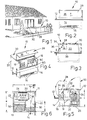
- ground Forming or transformer station 10 of the maximum viewing height h of about 1,000 mm above ground level 12 is below this in a front wall 14 with bushings 16 for Provide cables, not shown.
- Parallel side walls 22 of the front wall 14 close Length e of 2,300 mm, connected by a rear wall 24 are; Side walls 22 and rear wall 24 are together with the Front wall 14 and a base plate 26 monolithic made of concrete poured.
- the total height f of the side and rear walls 22, 24 corresponds approximately to that side length e.
- the transformer station 10 is at the top through a front cover 28 and a tailgate 30 complementing this, closed, both of which - as is particularly clear from FIG. 5 - - are to be opened in the same direction towards the rear wall 24; on these are hinges 32 for the boot lid 30.
- the front cover 28 is in Figs. 1 to 5 from a single Light metal plate made at a scanting angle w from just over 90 ° to one from the range of Hinges 32 to a front edge 34 downwardly inclined ridge section 35 and an apron section 36 is divided; the latter complements the front wall when closed 14.
- the ridge section 35 is on by the hinges 32 a gutter support - crossing the station interior 11 38 connected, which in an embodiment of FIG one with the floor slab 26 monolithically cast threshold 27 and at an average distance i of about 1,100 mm to the front wall 14.
- Both covers 28, 30 are via gas springs 29 on the side walls 24 supported and easily movable relative to this.
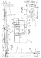
- the venting takes place on the one hand by means of passages 37 at the lower edge of the apron section 36, the other below the ridge section 35 according to the arrows y. This symbolize for example in Fig. 8 the air flows between Trunk lid 30 and top edge 23 of the side wall 22, the Thickness k measures 100 mm here.
- the reinforced by box profiles 42 and with an air grille 44 equipped trunk lid 30 is on the side with a vertical edge 46 L-shaped cross section - or one 8 in dashed lines indicated inclined lid edge 46a - provided.
- the exemplary embodiment in FIG. 9 contains an indentation 21 with an approximately horizontal shoulder 50 h and a length n of 1,200 mm in the concrete of the side wall 22 with an inserted channel support 38.
- the inclination angles t, t 1 of approximately 3 ° to 5 ° are particularly clear two covers or cover sections 30, 35 - and thus their cover surfaces 30 a , 35 a - recognizable.
- the channel support 38 may be used for draining water penetrating between the two lids 28, 30; the interior of the channel 39 engages under the roof gap 52 existing between the two lids 28, 30.
- the front cover 28 - like that 7 - made of two separate parts 35, 36; the apron section 36 is firmly attached to one Rectangular profile 54, which is connected to the ridge section 35 is.
- the width q of this ridge section 35 measures 1.325 mm, is therefore slightly longer than the concrete cut length n.
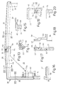
- FIG. 10 shows the hinge point X according to FIG. 9 with a hinge bracket 31 a fixed horizontally on an intermediate plate 25 a on the upper edge 23 of the rear wall 24 with the interposition of a stainless steel rail 25. This is curved outside the intermediate plate 25 a and below the surface of the intermediate plate - plane E - a horizontal eye 32 a for the lid-side hinge axis 33.
- the hinge bracket 31 a ends above an edge 46 e of the rear vertical edge 46.
- the front cover 28 of FIG. 13 is in turn bent from a single light metal plate 56.
- the vertical edge 46 in the region of the channel opening has a shortened height z (see FIG. 46 a in FIG. 11).
- FIGS. 13 to 19 let that of the corresponding Wall parts 14,22,24 on the one hand and the one at a distance opposite lids 28,30 and lid edges 46 limited Recognize flow space for ventilation (arrow y in Fig. 14).
- the apron section 36 of both illustrated embodiments contains for detachable connection to the one below Front wall 14 is a compact lock 72, as shown in FIG. 12 is indicated.
- a lock plate 74 On a lock plate 74 is a twist grip 76 stored, next to him is a lock case 78 with a PVC rosette 80 for a lock cylinder.
- a lock plate 74 On both sides the lock plate 74 is a movable in the pushing direction x Locking bracket 82 as a bearing for a pair of Associated locking rods 84; their tours on Apron sections are neglected in the drawing.
- space cells 10 described can be arranged next to one another and produced in one piece, as shown in FIG. 21 using a double cell 10 a , the length a 1 of which is slightly more than 400 cm and the width e of which is approximately 230 cm.
Landscapes
- Engineering & Computer Science (AREA)
- Power Engineering (AREA)
- Laying Of Electric Cables Or Lines Outside (AREA)
- Housings And Mounting Of Transformers (AREA)
- Tents Or Canopies (AREA)
- Casings For Electric Apparatus (AREA)
- Transmitters (AREA)
Description
- eine Deckeloberfläche mit Gefälle sowie Wasserablauf nach vorn und hinten, wodurch jede Wasserlachenbildung auf den Deckeln verhindert wird, ebenso Sturzwasser in dem über den Schaltanlagen liegenden Rinnenträger beim Öffnen des Frontdeckels;
- einen Frontdeckel aus Blech mit erhöhter Stabilität durch die Konstruktion aus einem Stück;
- die Scharnierausbildung des Heckdeckels bietet den Drehpunkt innerhalb der dreiseitig umlaufenden, gleichen Deckelrandausbildung an; durch einen zusätzlichen Bug des dortigen Deckelbleches im hinteren Bereich entsteht eine völlige Abdeckung des dortigen Scharniers gegen Zugänglichkeit von außen;
- die Bedienung der Deckel ist am Frontdeckel durch ein Kompaktstationsschloß mit Drehgriff und Schließzylinder verbessert, am Heckdeckel durch eine dreifache Schiebe-/Drehverriegelung;
- die senkrechte Abkantung des Deckelrandes ergibt einen ausreichenden Abstand der Wasserabtropfkante von der Stationswand, um eine gute Wirksamkeit der Rundumentlüftung durch optimierte Luftführung zu ermöglichen; zudem ist dadurch zusätzlich die Handhabung des Heckdeckels beim Schließvorgang erleichtert;
- das optische Erscheinungsbild erfaßt:
- Verkleinerung der Deckelfläche durch Gefälleausbildung, dadurch auch optische Reduzierung der Stationshöhe;
- gestalterische und funktionelle Einheit des Deckels;
- harmonisierte Ansicht durch einheitliche, dreiseitig umlaufende Ausbildung des Deckelrandes mit geradlinigem Übergang in den senkrechten Schürzenabschnitt.
- Fig. 1:
- eine Schrägsicht auf eine vor einem Wohnhaus angeordnete, nicht begehbare Transformatorenstation mit zwei als Überdachung dienenden Deckeln in geschlossenem Zustand;
- Fig. 2:
- die Frontansicht der Trafostation mit einem gestrichelt angedeuteten untertägigen Teil;
- Fig. 3:
- eine Seitenansicht zu Fig. 2;
- Fig. 4:
- eine Schrägsicht auf die Trafostation mit geöffnetem Frontdeckel;
- Fig. 5:
- einen Querschnitt durch die geschlossene Trafostation, geschnitten nach Linie V-V in Fig. 6;
- Fig. 6:
- die Draufsicht auf die Trafostation ohne Deckel;
- Fig. 7:
- den gegenüber Fig. 1 bis 6 vergrößerten Querschnitt durch eine andere Ausgestaltung der Trafostation mit Front- und Heckdeckel;
- Fig. 8:
- einen vergrößerten Teilschnitt aus Fig. 7 nach deren Linie VIII-VIII;
- Fig. 9:
- einen Teilquerschnitt durch eine andere Trafostation mit einem Scharnierbereich des Frontdeckels als Zenit der Abdeckung, von dem sowohl der Frontdeckel als auch ein Heckdeckel abwärts geneigt verlaufen;
- Fig. 10:
- ein vergrößertes Detail aus Fig. 9 nach deren Pfeil X;
- Fig. 11:
- ein vergrößertes Detail aus Fig. 10 nach deren Pfeil XI;
- Fig. 12:
- die Draufsicht auf ein Kompaktschloß, das in den Frontdeckel bei Pfeil XII eingesetzt ist;
- Fig. 13:
- eine andere Ausgestaltung der Abdeckung der Trafostation im Querschnitt;
- Fig. 14 bis Fig. 17:
- Teilquerschnitte durch Fig. 13 nach deren Linien XIV-XIV bis XVII-XVII;
- Fig. 18:
- eine Darstellung des Bereiches der Fig. 17 in anderer Betriebsstellung;
- Fig. 19:
- einen Horizontalschnitt durch eine Ecke der Umspannstation;
- Fig. 20:
- einen Vertikalschnitt durch Fig. 19 nach deren Linie XX-XX;
- Fig. 21:
- eine Schrägsicht auf eine Doppelstation.
Claims (11)
- Transportable Raumzelle in Form einer teilweise in Erdreich abgesenkten, einen Innenraum für einen Transformator, für Hoch-, Mittel- und/oder Niederspannungsschaltgeräte od. dgl. Anlagenteile (18, 19) enthaltenden Umspannstation mit vier Wandteilen (14, 22, 24), die gegebenenfalls monolithisch mit einer Bodenplatte (26) verbunden sind, sowie mit einer Überdachung aus beidseits eines den Stationsinnenraum (11) übergreifenden, sich nach oben öffnenden Rinnenträgers (38) angeordneten und getrennt um zueinander parallele Gelenke (32) schwenkbaren Deckeln (28,30), welche mit Lüftungsschlitzen (37) versehen sind und/oder mit dem ihnen zugeordneten Wandteil (14, 22, 24) einen Strömungsweg vom/zum Zelleninnenraum (11) begrenzen, wobei einer der Deckel (28) mit einem Firstabschnitt (35) am Rinnentrager (38) angelenkt ist und einen zur Ebene des Firstabschnittes (35) abgewinkelten Schürzenabschnitt (36) aufweist, der in geschlossenem Zustand der Umspannstation (10) den oberen Teil eines Wandteils (14) bildet, sowie der andere Deckel (30) an der dem Schürzenabschnitt gegenüber liegenden Wandteil (24) angelenkt ist und mit den Oberkanten (23) zugeordneter Wandteile (22, 24) wenigstens einen Strömungsweg begrenzen.
- Raumzelle nach Anspruch 1, wobei die Deckel (28,30) vom Rinnenträger (38) zu den diesen parallelen Wandteilen (14,24) abwärts und gegenläufig geneigt sind.
- Raumzelle nach Anspruch 1 oder 2, wobei am Deckel (30) bzw. am Firstabschnitt (35) ein Ende wenigstens eines Kraftspeichers (29) angelenkt ist, der sich andernends am benachbarten Wandteil (22) abstützt.
- Raumzelle nach Anspruch 3, wobei am Deckel (30) bzw. der Firstabschnitt (35) parallel zu seiner Seitenwand (46) innerhalb des Zelleninnenraums (11) in Abstand zum Wandteil (22) mit einem Verstärkungsprofil (66) für den Kraftspeicher (29) versehen ist.
- Raumzelle nach einem der Ansprüche 1 bis 4, wobei bei dem den Schürzenabschnitt (36) aufweisenden Deckel (28) zwischen dessen Firstabschnitt (35) und dem Schürzenabschnitt wenigstens ein Lüftungsschlitz verläuft.
- Raumzelle nach einem der Ansprüche 1 bis 5, wobei oberhalb der Oberkante der vom Schürzenabschnitt (36) ergänzbaren Frontwand (14) in die Innenfläche der Seitenwand (24) eine Schulter (50) eingeformt ist, die nahe jener Oberkante und unterhalb des Rinnenträgers (38) horizontal und dazwischen geneigt verläuft.
- Raumzelle nach einem der Ansprüche 1 bis 6, wobei unterhalb der Oberkante der Seitenwand (24) in deren Innenfläche eine Schulter (50a) als Teil einer Einformung (21) von der Frontwand (14) horizontal verläuft und hinter dem Rinnenträger (38) endet.
- Raumzelle nach einem der Ansprüche 1 bis 7, wobei oberhalb der Oberkante ihrer vom Schürzenabschnitt (36) ergänzbaren Frontwand (14) in die Außenfläche der Seitenwand (24) ein taschenartiger Randeinschnitt (60) eingeformt ist.
- Raumzelle nach einem der Ansprüche 1 bis 8, wobei am Schürzenabschnitt (36) des Frontdeckels (28) ein Kompaktschloß (72) mit Drehgriff (76) und Schließzylinder als Schließorgan vorgesehen ist.
- Raumzelle nach Anspruch 9, wobei am Heckdeckel (30) eine dreifache Schiebe/Drehverriegelung vorgesehen ist.
- Raumzelle nach wenigstens einem der Ansprüche 1 bis 10, wobei mehrere Raumzellen als Baueinheit (10a) nebeneinander angeordnet sind.
Applications Claiming Priority (4)
| Application Number | Priority Date | Filing Date | Title |
|---|---|---|---|
| DE19538268 | 1995-10-13 | ||
| DE19538268 | 1995-10-13 | ||
| DE19614593 | 1996-04-12 | ||
| DE19614593A DE19614593A1 (de) | 1995-10-13 | 1996-04-12 | Transportable Raumzelle als Umspannstation |
Publications (3)
| Publication Number | Publication Date |
|---|---|
| EP0768741A2 EP0768741A2 (de) | 1997-04-16 |
| EP0768741A3 EP0768741A3 (de) | 1997-08-20 |
| EP0768741B1 true EP0768741B1 (de) | 2001-08-01 |
Family
ID=26019484
Family Applications (1)
| Application Number | Title | Priority Date | Filing Date |
|---|---|---|---|
| EP96115760A Expired - Lifetime EP0768741B1 (de) | 1995-10-13 | 1996-10-02 | Transportable Raumzelle als Umspannstation |
Country Status (3)
| Country | Link |
|---|---|
| EP (1) | EP0768741B1 (de) |
| AT (1) | ATE203856T1 (de) |
| PL (1) | PL180976B1 (de) |
Families Citing this family (7)
| Publication number | Priority date | Publication date | Assignee | Title |
|---|---|---|---|---|
| EP0942442B1 (de) * | 1998-03-13 | 2003-05-07 | EnBW Badenwerk AG | Umspannstation in Kompaktbauweise |
| ES1053250Y (es) | 2002-11-06 | 2003-07-01 | Twelcon Electronica S L | Centro especial de transformacion urbano. |
| EP1500757B1 (de) | 2003-07-23 | 2009-10-28 | Prefabricados Uniblok,S.L.U. | Vorgefertigte Konstruktion mit durchgehbarem Deckel für industrielle Anwendungen |
| CN1885648A (zh) * | 2006-06-01 | 2006-12-27 | 冯骏明 | 具有信息互动及广告传媒功能的电力设施及其应用方法 |
| PL216600B1 (pl) | 2009-05-25 | 2014-04-30 | ABB Spółka z ograniczoną odpowiedzialnością | Zestaw do konstrukcji obudowy dla modułowych rozdzielnic podstacji energetycznych rozdziału wtórnego |
| CN102263381B (zh) * | 2011-08-11 | 2014-01-22 | 浙江安可电气科技有限公司 | 半埋式箱式变电站的下箱体结构 |
| WO2017044830A1 (en) | 2015-09-11 | 2017-03-16 | Younicos Inc. | Modular energy storage system |
Family Cites Families (8)
| Publication number | Priority date | Publication date | Assignee | Title |
|---|---|---|---|---|
| DE2401532C3 (de) * | 1974-01-14 | 1979-09-13 | Rudolf Dipl.-Ing. 7000 Stuttgart Koerber | Begehbare Mittelspannungsnetzstation in Niedrigbauweise |
| FR2341972A1 (fr) * | 1976-02-17 | 1977-09-16 | Merlin Gerin | Poste prefabrique semi-enterre de transformation moyenne tension-basse tension |
| DE2706959A1 (de) * | 1977-02-18 | 1978-08-24 | Gervin Josef Mueller | Teilweise in das erdreich einsenkbare, transportable energieverteilungs- und/oder erzeugungsstation |
| FR2417196A1 (fr) * | 1978-02-08 | 1979-09-07 | Denizet Rene | Cabine de transformation electrique |
| US4644095A (en) * | 1985-02-14 | 1987-02-17 | Western Power Products, Inc. | Enclosure for outdoor, ground level mounted communication equipment |
| DE8519621U1 (de) * | 1985-07-06 | 1985-10-03 | Betonbau GmbH, 6833 Waghäusel | Transportable Umspannstation |
| US4821143A (en) * | 1987-10-30 | 1989-04-11 | Cooper Power Systems, Inc. | Switchgear enclosure with improved supporting frame and improved access door |
| CH682961A5 (fr) * | 1990-04-12 | 1993-12-15 | Bsa Ingenieurs Conseils | Station transformatrice enterrée au moins partiellement. |
-
1996
- 1996-10-02 AT AT96115760T patent/ATE203856T1/de not_active IP Right Cessation
- 1996-10-02 EP EP96115760A patent/EP0768741B1/de not_active Expired - Lifetime
- 1996-10-11 PL PL96316493A patent/PL180976B1/pl unknown
Also Published As
| Publication number | Publication date |
|---|---|
| EP0768741A3 (de) | 1997-08-20 |
| PL316493A1 (en) | 1997-04-14 |
| EP0768741A2 (de) | 1997-04-16 |
| ATE203856T1 (de) | 2001-08-15 |
| PL180976B1 (pl) | 2001-05-31 |
Similar Documents
| Publication | Publication Date | Title |
|---|---|---|
| EP0768741B1 (de) | Transportable Raumzelle als Umspannstation | |
| DE3423184A1 (de) | Unterflurstation fuer kabelverzweigergehaeuse, insbesondere kabelverzweigerschraenke o. dgl. kabelverzweigereinrichtungen | |
| EP0878808B1 (de) | Elektrische Umspannstation | |
| EP0563436A1 (de) | Transportable Raumzelle und Verfahren zum herstellen einer Raumzelle | |
| EP0465935A1 (de) | Raumzelle | |
| DE7621359U1 (de) | Fenster mit schwenkbaren fensterfluegeln | |
| EP0343356B1 (de) | Netzstation oder dergleichen mit Be- und Entlüftungsöffnungen für einen Lüftungsstrom | |
| DE19614593A1 (de) | Transportable Raumzelle als Umspannstation | |
| EP0303993B1 (de) | Längsverschiebbare Flachdachpfanne | |
| EP0209027B1 (de) | Transportable Umspannstation | |
| DE2816210C2 (de) | Teilweise in das Erdreich einsenkbares Stationsgebäude | |
| EP0465934B1 (de) | Raumzelle | |
| DE2401532A1 (de) | Begehbare mittelspannungsnetzstation aus fertigteilen | |
| DE4307478C2 (de) | Vorrichtung zum Verschließen einer Wandöffnung, insbesondere eines Zuganges für eine Schaltstation | |
| DE10336910A1 (de) | Transformatorenstation | |
| DE19752153B4 (de) | Vorrichtung zur Herstellung einer tansportablen Raumzelle als Umspannstation | |
| DE19710810A1 (de) | Transportable Raumzelle als Umspannstation | |
| DE19649238B4 (de) | Vorrichtung zum Verschließen eines Wanddurchbruches, insbesondere eines Zuganges, einer Schaltstation | |
| DE4301137C1 (de) | Stauklappenwehr | |
| EP0522514B1 (de) | Gehäusekasten für aufrollbare Lichtbildwand | |
| DE3524539C2 (de) | Kabelverzweigerschrank | |
| DE10009013A1 (de) | Transportable Raumzelle als Umspannstation | |
| DE3824668C1 (en) | Cable-pull arrangement for opening and closing a window blind | |
| DE19746118A1 (de) | Gehäuse | |
| DE7523233U (de) | Energieverteilungsstation insbesondere umformstation |
Legal Events
| Date | Code | Title | Description |
|---|---|---|---|
| PUAI | Public reference made under article 153(3) epc to a published international application that has entered the european phase |
Free format text: ORIGINAL CODE: 0009012 |
|
| AK | Designated contracting states |
Kind code of ref document: A2 Designated state(s): AT BE DE FR |
|
| AX | Request for extension of the european patent |
Free format text: LT;LV;SI |
|
| PUAL | Search report despatched |
Free format text: ORIGINAL CODE: 0009013 |
|
| RBV | Designated contracting states (corrected) |
Designated state(s): AT BE DE FR |
|
| AK | Designated contracting states |
Kind code of ref document: A3 Designated state(s): AT BE CH DE DK ES FR GB GR IE IT LI LU MC NL PT SE |
|
| AX | Request for extension of the european patent |
Free format text: LT;LV;SI |
|
| 17P | Request for examination filed |
Effective date: 19970918 |
|
| 17Q | First examination report despatched |
Effective date: 19981106 |
|
| GRAG | Despatch of communication of intention to grant |
Free format text: ORIGINAL CODE: EPIDOS AGRA |
|
| GRAG | Despatch of communication of intention to grant |
Free format text: ORIGINAL CODE: EPIDOS AGRA |
|
| GRAH | Despatch of communication of intention to grant a patent |
Free format text: ORIGINAL CODE: EPIDOS IGRA |
|
| GRAH | Despatch of communication of intention to grant a patent |
Free format text: ORIGINAL CODE: EPIDOS IGRA |
|
| GRAA | (expected) grant |
Free format text: ORIGINAL CODE: 0009210 |
|
| AK | Designated contracting states |
Kind code of ref document: B1 Designated state(s): AT BE DE FR |
|
| REF | Corresponds to: |
Ref document number: 203856 Country of ref document: AT Date of ref document: 20010815 Kind code of ref document: T |
|
| REF | Corresponds to: |
Ref document number: 59607406 Country of ref document: DE Date of ref document: 20010906 |
|
| PG25 | Lapsed in a contracting state [announced via postgrant information from national office to epo] |
Ref country code: AT Free format text: LAPSE BECAUSE OF NON-PAYMENT OF DUE FEES Effective date: 20011002 |
|
| PG25 | Lapsed in a contracting state [announced via postgrant information from national office to epo] |
Ref country code: BE Free format text: LAPSE BECAUSE OF NON-PAYMENT OF DUE FEES Effective date: 20011031 |
|
| EN | Fr: translation not filed | ||
| BERE | Be: lapsed |
Owner name: BETONBAU G.M.B.H. Effective date: 20011031 |
|
| EN | Fr: translation not filed |
Free format text: BO 01/52 PAGES: 283, IL Y A LIEU DE SUPPRIMER: LA MENTION DE LA NON REMISE. LA REMISE EST PUBLIEE DANS LE PRESENT BOPI. |
|
| ET | Fr: translation filed | ||
| PLBE | No opposition filed within time limit |
Free format text: ORIGINAL CODE: 0009261 |
|
| STAA | Information on the status of an ep patent application or granted ep patent |
Free format text: STATUS: NO OPPOSITION FILED WITHIN TIME LIMIT |
|
| 26N | No opposition filed | ||
| PGFP | Annual fee paid to national office [announced via postgrant information from national office to epo] |
Ref country code: DE Payment date: 20040728 Year of fee payment: 9 |
|
| PGFP | Annual fee paid to national office [announced via postgrant information from national office to epo] |
Ref country code: FR Payment date: 20041020 Year of fee payment: 9 |
|
| PG25 | Lapsed in a contracting state [announced via postgrant information from national office to epo] |
Ref country code: DE Free format text: LAPSE BECAUSE OF NON-PAYMENT OF DUE FEES Effective date: 20060503 |
|
| PG25 | Lapsed in a contracting state [announced via postgrant information from national office to epo] |
Ref country code: FR Free format text: LAPSE BECAUSE OF NON-PAYMENT OF DUE FEES Effective date: 20060630 |
|
| REG | Reference to a national code |
Ref country code: FR Ref legal event code: ST Effective date: 20060630 |