EP0768734B1 - Elektrischer Steckverbinder - Google Patents
Elektrischer Steckverbinder Download PDFInfo
- Publication number
- EP0768734B1 EP0768734B1 EP96116607A EP96116607A EP0768734B1 EP 0768734 B1 EP0768734 B1 EP 0768734B1 EP 96116607 A EP96116607 A EP 96116607A EP 96116607 A EP96116607 A EP 96116607A EP 0768734 B1 EP0768734 B1 EP 0768734B1
- Authority
- EP
- European Patent Office
- Prior art keywords
- connector
- male connector
- locking arm
- female connector
- face
- Prior art date
- Legal status (The legal status is an assumption and is not a legal conclusion. Google has not performed a legal analysis and makes no representation as to the accuracy of the status listed.)
- Expired - Lifetime
Links
Images


Classifications
-
- H—ELECTRICITY
- H01—ELECTRIC ELEMENTS
- H01R—ELECTRICALLY-CONDUCTIVE CONNECTIONS; STRUCTURAL ASSOCIATIONS OF A PLURALITY OF MUTUALLY-INSULATED ELECTRICAL CONNECTING ELEMENTS; COUPLING DEVICES; CURRENT COLLECTORS
- H01R13/00—Details of coupling devices of the kinds covered by groups H01R12/70 or H01R24/00 - H01R33/00
- H01R13/62—Means for facilitating engagement or disengagement of coupling parts or for holding them in engagement
- H01R13/627—Snap or like fastening
- H01R13/6271—Latching means integral with the housing
- H01R13/6272—Latching means integral with the housing comprising a single latching arm
-
- H—ELECTRICITY
- H01—ELECTRIC ELEMENTS
- H01R—ELECTRICALLY-CONDUCTIVE CONNECTIONS; STRUCTURAL ASSOCIATIONS OF A PLURALITY OF MUTUALLY-INSULATED ELECTRICAL CONNECTING ELEMENTS; COUPLING DEVICES; CURRENT COLLECTORS
- H01R13/00—Details of coupling devices of the kinds covered by groups H01R12/70 or H01R24/00 - H01R33/00
- H01R13/62—Means for facilitating engagement or disengagement of coupling parts or for holding them in engagement
- H01R13/629—Additional means for facilitating engagement or disengagement of coupling parts, e.g. aligning or guiding means, levers, gas pressure electrical locking indicators, manufacturing tolerances
Definitions
- the invention relates to an electrical connector according to the precharacterizing part of claim 1 or 5.
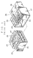
- Fig. 8 shows a female connector in a conventional used electrical connector.
- This female connector 20 has bending preventing rib 22 projected on an inner wall face 21' of a hood 21 which receives a male connector (not shown).
- the bending preventing ribs 22 are arranged between terminals (not shown) inserted into the female connector 20. And when the female connector 20 and the male connector are mistakenly slantly fitted, in order that the male connector and the bending preventing ribs 22 are caused to contact to each other, being bent of any of the terminals in the female connector 20 are prevented.
- Being bent means the condition that female and male terminals aren't contacted electrically to each other because any of male terminals are bent.
- Fig. 9 shows an electrical connector that is composed of a raised portion 24' mounted on a sidewall of a male connector 23, and a locking arm 24 formed at the raised portion 24', and guide ribs 25, 25 mounted on both sides of the locking arm 24, and a locking arm chamber 28 for accommodating the locking arm 24 at the hood 27 of the female connector 26, and guide grooves 29 for leading to guide ribs 25.
- a electrical connector (described in JAPANESE UTILITY MODEL APPLICATION laid-open No. 60-166981) that is composed of a perpendicular engaging piece 34 formed on a locking chamber 33 of a hood 32 in a female connector 31, and a guide groove 37 formed at a raised portion 36 on front end of a male connector 35 in order to guide the engaging piece 34.
- US-A-5 378 168 discloses corresponding to the first part of claim 1 an electrical connector having a locking arm, a bending preventing member preventing an improper connection, and a complementary separate recess for locating the member at the longitudinal axis of the connector.
- EP-A-0 448 084 discloses an electrical connector comprising a resilient locking arm at the female connector and a corresponding engagement projection at the male connector.
- US-A-5 425 650 discloses corresponding to the first part 1 of claim 5 a connector having a locking arm between a pair of slits formed in the side wall, and an inclined bending prevention member as a part of a guide projection.
- An objection of the present invention is to provide an electrical connector that prevents being bent of terminals in a female connector from causing and a locking arm from deforming and being damaged when a male connector and a female connector are mistakenly and slantly fitted together, and that is easily able to control the reaction force of a raised portion in a manner utilizing the locking arm chamber or a wall portion from which the locking arm protrudes.
- a bending preventing member is protruded on a wall face of said female connector, extending toward said male connector, and an escape portion is formed in a front end face of said locking arm of said male connector on the side of said female connector, allowing said bending preventing member to enter, and being bent of any terminals in said female connector is prevented by contacting to said bending preventing member and a front end face or a sidewall of said male connector when said male connector and said female connector are slantly fitted together.
- a pair of guide ribs is formed on a front end face of said male connector by recessing at least one side in said escape portion, or a pair of guide grooves is formed at a hood of said female connector for leading to said guide ribs.
- a raised portion which has said escape portion is formed at said locking arm by recessing on a front end face of said male connector, and a locking arm chamber which receives said locking arm is formed at said hood, and said locking arm chamber has said bending preventing member.
- guide ribs at a front end face in the male connector, and guide grooves at the female connector for leading to the guide ribs, when the male connector and the female connector are fitted slantly, the guide ribs strike the guide grooves, and the terminals are moreover prevented from being bent.
- the configuration of the escape portion for corresponding to the bending preventing member is different from that of the conventional used guide grooves, wires and the hood of the female connector do not hang the escape portion. Therefore the locking arm is prevented from deforming and being damaged, and it is easily to adjust the reaction force of the locking arm. Furthermore because the bending preventing member is formed in the locking arm chamber for accommodating the locking arm, the locking arm chamber is not divided by the bending preventing member. Therefore it is possible to make use of the locking arm chamber widely.
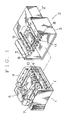
- Fig. 1 to Fig. 3 shows the first embodiment of the present invention which is an electrical connector.
- a male connector 1 and another female connector 2 is fitted together.
- plural terminal chambers 1' are arranged in the form of two up-and-down columns, open back and forth, and a locking arm 4 is formed in a raised portion 4' mounted on an upper wall.
- Guide ribs 7, 7 are located on both sides of the locking arm 4.
- a hood 3 is formed at a front end for accommodating the male connector 1.
- a locking arm chamber 5 is formed in the hood 3 for accommodating the locking arm 4.
- Guide grooves 8, 8 are formed on both sides of the locking arm chamber 5 for leading to the guide ribs 7, 7. Terminals 11 extends from the front end of the housing body 2' into the hood 3.
- a bending preventing piece 9 as a bending preventing member is protruded toward the male connector 1 from the front end of the housing body 2'.
- the bending preventing piece 9 is elastic and is formed with a thin plate in shape.
- the bending preventing piece 9 is longer than terminals 11 projected from the front end of the housing body 2'. And it is proper to make smooth a tip of the bending preventing piece 9.
- An escape portion 10 which allows ingress of the bending preventing piece 9 is formed in the raised portion 4'.
- the escape portion 10 is size so that there is surplus in space inside, inserting the bending preventing piece 9.
- the male connector 1 slightly enters in the direction of the terminals 11 in the hood 3, but because the bending preventing piece 9 is formed longer than the terminals 11 protruded from a front end of the housing body 2', the male connector 1 and the female connector 2 are not fitted together.
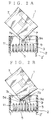
- Fig. 4 shows the second embodiment of the present invention which is an electrical connector.
- the second embodiment which corresponds to the components in the first embodiment will be given the same number as the first embodiment.
- a pair of concave portions or a pair of slits 12, 12 are formed at an upper wall face 1a in the male connector 1, the locking arm 4 is mounted between the concave portions 12, 12, and an escape portion 10' which allows ingress of an bending preventing piece 9' described later is formed a front end face 1b.
- a bending preventing piece 9' as a bending preventing member is protruded from a front end face 2a of the female connector 2 nearer to an opening 3a in the hood 3.
- the bending preventing piece 9' is the same configuration as that of the first embodiment, the detailed description about the bending preventing piece 9' will be omitted herein.
- the guide ribs 7 ( Fig. 1 ) on at least one side of the escape portion 10' by recessing the front end face 1b of the male connector 1.
- the guide grooves 8 ( Fig. 1 ) leading to the guide ribs 7 in the hood 3 of the female connector 2.
- the raised portion 4' ( Fig. 1 ) by recessing the front end face 1b in the male connector 1 and the escape portion 10' at the raised portion 4', and to form the locking arm chamber 5 for accommodating the locking arm 4 in the hood 3 of the female connector 2 and the bending preventing piece 9' in the locking arm chamber 5.
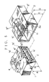
- Fig. 5 to Fig. 6 shows the third embodiment of the present invention which is an electrical connector.
- the male connector 1 has a upper wall face 1a' which is formed flatly with the height A from a lower wall face 1c'.
- the locking arm 4 is formed at a raised portion 4'' mounted in a front end face 1b'.
- the hood 3 of the female connector 2 has a locking arm chamber 5' for accommodating the locking arm 4.
- a bending preventing piece 9'' is protruded on the female connector 2.
- An escape portion 10'' is formed in the raised portion 4'' for allowing ingress of the bending preventing piece 9''. Because the bending preventing piece 9'' is the same configuration as that of the first embodiment, the detailed explanation about the bending preventing piece 9'' will be omitted herein.
- the escape portion 10'' formed with the height B from a lower wall face 1c' in the male connector 1 and, as shown in Fig. 6B, the bending preventing piece 9'' formed with the height C from a lower wall face 2c' in the female connector 2 are located individually so that the relation of B ⁇ C ⁇ A is satisfied.
- any of the terminals 11 is prevented from being bent by striking a sidewall 6b'' of a raised wall 6 formed on a front end face 1b'' side of an upper wall face 1a'' in the male connector 1, and the bending preventing piece 9'' in the female connector 2.
- the bending preventing piece 9 ( 9', 9'' ) is protruded at the center within an upper half in the hood 3 of the female connector 2, but it is also possible to protrude the bending preventing piece 9 (9', 9'' ) at other location within the upper half in the hood 3. If the bending preventing piece 9 (9', 9'' ) is arranged at the center in the case that either left or right side of the male connector 1 and the female connector 2 are fitted slantly, because any of the terminals 11 is prevented from being bent, the bending preventing piece 9 (9', 9'' ) is located at the center in the hood 3 more properly than at either left or right.
Claims (5)
- Ein elektrischer Steckverbinder, mit:einem Steckerteil (1), das eine Mehrzahl von Anschlusskammern (1') in der vorderen Endseite des Steckerteils (1) aufweist;einem Buchsenteil (2), das das Steckerteil (1) aufnimmt und eine Mehrzahl von Anschlussstiften (11) aufweist, die von einer Wandseite des Buchsenteils (2) vorstehen und die in die Anschlusskammern (1') des Steckerteils (1) eingesetzt werden; wobeidas Steckerteil (1) einen Verriegelungsarm (4) aufweist, der an einer Seitenwand (1a', 1a") des Steckerteils (1) ausgebildet ist, und das Buchsenteil (2) eine Verriegelungsarmkammer (5, 5') aufweist, die den Verriegelungsarm (4) aufnimmt; und wobeiein Verbiegungsschutzbauteil (9, 9"), das länger als die Anschlussstifte (11) ist, von der Wandfläche des Buchsenteils (2) vorsteht und ein Ausweichabschnitt (10, 10") in der vorderen Endseite des Steckerteils (1) für das Aufnehmen des Verbiegungsschutzbauteils (9, 9') ausgebildet ist, dadurch gekennzeichnet, dassdas Verbiegungsschutzbauteil (9, 9") in der Verriegelungsarmkammer (5, 5') in Ausrichtung mit dem Ausweichabschnitt (10, 10"), in der vorderen Endseite des Verriegelungsarms (4) angeordnet ist.
- Ein elektrischer Steckverbinder nach Anspruch 1, wobei ein erhöhter Bereich (4', 4") am vorderen Ende des Verriegelungsarms (4) des Steckerteils (1) ausgebildet ist.
- Ein elektrischer Steckverbinder nach Anspruch 1 oder 2, wobei ein Paar Führungsrippen (7) zu beiden Seiten des Verriegelungsarms (4) des Steckerteils (1) in dessen Einführungsrichtung ausgebildet sind und ein Paar entsprechender Führungsnuten (8) zu beiden Seiten der Verriegelungsarmkammer (5) des Buchsenteils (2) zum Führen der Führungsrippen (7) ausgebildet sind.
- Ein elektrischer Steckverbinder gemäss Anspruch 1 oder 2, wobei eine erhöhte Wand (6) am vorderen Ende der Seitenwand (1a") des Steckerteils (1) ausgebildet ist.
- Ein elektrischer Steckverbinder, mit:einem Steckerteil (1) mit einer Mehrzahl von Anschlusskammem (1') in einer vorderen Endseite des Steckerteils;einem Buchsenteil (2) für die Aufnahme des Steckerteils (1) mit einer Mehrzahl elektrischer Anschlussstifte (11), die von einer Wandseite des Buchsenteils (2) zum Einstecken in die Anschlusskammem (1') des Steckerteils (1) vorstehen; wobeidas Steckerteil (1) einen Verriegelungsarm (4) aufweist, der an einer Seitenwand (1a) des Steckerteils (1) zwischen einem Paar von Schlitzen (12) ausgebildet ist, die in der Seitenwand (1a) ausgebildet sind; und wobeiein Verbiegungsschutzbauteil (9'), das länger als die Anschlussstifte (11) ist, von der Wandseite des Buchsenteils (2) vorsteht und einen Ausweichabschnitt (10') in der vorderen Endseite des Steckerteils (1) zur Aufnahme des Verbiegungsschutzbauteils (9') ausgebildet ist, dadurch gekennzeichnet, dassder Ausweichabschnitt (10') in einem Bereich der vorderen Endseite (1b) der Seitenwand (1a), von der der Verriegelungsarm (4) vorsteht, ausgebildet ist und das Verbiegungsschutzbauteil (9') an der Wandseite, die mit dem Ausweichabschnitt (10') in der Seitenwand (1a) ausgerichtet wird, angeordnet ist.
Applications Claiming Priority (3)
| Application Number | Priority Date | Filing Date | Title |
|---|---|---|---|
| JP26666895 | 1995-10-16 | ||
| JP266668/95 | 1995-10-16 | ||
| JP26666895A JP3183382B2 (ja) | 1995-10-16 | 1995-10-16 | 電気コネクタ |
Publications (3)
| Publication Number | Publication Date |
|---|---|
| EP0768734A2 EP0768734A2 (de) | 1997-04-16 |
| EP0768734A3 EP0768734A3 (de) | 1998-01-14 |
| EP0768734B1 true EP0768734B1 (de) | 2001-01-03 |
Family
ID=17434039
Family Applications (1)
| Application Number | Title | Priority Date | Filing Date |
|---|---|---|---|
| EP96116607A Expired - Lifetime EP0768734B1 (de) | 1995-10-16 | 1996-10-16 | Elektrischer Steckverbinder |
Country Status (5)
| Country | Link |
|---|---|
| US (1) | US5775932A (de) |
| EP (1) | EP0768734B1 (de) |
| JP (1) | JP3183382B2 (de) |
| DE (1) | DE69611423T2 (de) |
| ES (1) | ES2153529T3 (de) |
Families Citing this family (18)
| Publication number | Priority date | Publication date | Assignee | Title |
|---|---|---|---|---|
| JP3561143B2 (ja) * | 1998-04-02 | 2004-09-02 | 矢崎総業株式会社 | ロック構造 |
| JP3521772B2 (ja) * | 1998-11-26 | 2004-04-19 | 住友電装株式会社 | コネクタ |
| US6183287B1 (en) * | 1998-12-31 | 2001-02-06 | Hon Hai Precision Ind. Co., Ltd. | Electrical connector |
| JP3851746B2 (ja) * | 1999-08-25 | 2006-11-29 | 住友電装株式会社 | コネクタ |
| JP4127938B2 (ja) * | 1999-08-31 | 2008-07-30 | 住友電装株式会社 | コネクタ |
| JP3567818B2 (ja) * | 1999-09-28 | 2004-09-22 | 住友電装株式会社 | コネクタ |
| JP3840039B2 (ja) * | 2000-06-01 | 2006-11-01 | 矢崎総業株式会社 | 慣性ロックコネクタ |
| JP2002184522A (ja) * | 2000-12-12 | 2002-06-28 | Jst Mfg Co Ltd | ロック機構付コネクタ・アセンブリー |
| US6435895B1 (en) * | 2001-04-27 | 2002-08-20 | Delphi Technologies, Inc. | Connector position assurance device |
| JP3976134B2 (ja) * | 2001-09-05 | 2007-09-12 | 矢崎総業株式会社 | 半嵌合防止コネクタ |
| JP2004063135A (ja) * | 2002-07-25 | 2004-02-26 | Yazaki Corp | コネクタ構造 |
| JP2007220557A (ja) | 2006-02-17 | 2007-08-30 | Tyco Electronics Amp Kk | 電気コネクタ組立体 |
| ES2740673T3 (es) * | 2007-10-16 | 2020-02-06 | Hirschmann Automotive Gmbh | Acoplamiento y enchufe de una conexión de enchufe con seguridad Koshiri |
| JP6138428B2 (ja) * | 2012-05-29 | 2017-05-31 | 矢崎総業株式会社 | コネクタ |
| DE102012025107A1 (de) * | 2012-12-21 | 2014-06-26 | Erni Production Gmbh & Co. Kg | Steckverbinderanordnung |
| US9660406B2 (en) * | 2013-08-30 | 2017-05-23 | The Patent Store Llc | Push-in wire connector with collar |
| JP6924385B2 (ja) * | 2018-01-19 | 2021-08-25 | 住友電装株式会社 | コネクタ |
| CN113178745B (zh) * | 2021-04-22 | 2021-11-30 | 东莞市思索连接器有限公司 | 一种便于维修的连接器 |
Family Cites Families (9)
| Publication number | Priority date | Publication date | Assignee | Title |
|---|---|---|---|---|
| US4273403A (en) * | 1980-02-01 | 1981-06-16 | Ford Motor Company | Locking structure for electrical connectors |
| JPS5841745A (ja) * | 1981-09-08 | 1983-03-11 | 三菱重工業株式会社 | セメント原料予配装置 |
| JPS5841745U (ja) * | 1981-09-10 | 1983-03-19 | 東芝テック株式会社 | ソ−タ−の収納ビン支持装置 |
| JPS60166981A (ja) * | 1984-02-10 | 1985-08-30 | 富士ゼロックス株式会社 | グラフイツクデイスプレイ装置 |
| JPS60166981U (ja) * | 1984-04-16 | 1985-11-06 | 日本航空電子工業株式会社 | コネクタ |
| US4806123B1 (en) * | 1987-02-03 | 1997-12-23 | Furukawa Electric Co Ltd | Electrical connector device with a number of terminals |
| JPH0770337B2 (ja) * | 1990-03-23 | 1995-07-31 | 矢崎総業株式会社 | コネクタの結合検知装置 |
| JP2593281Y2 (ja) * | 1992-10-06 | 1999-04-05 | 住友電装株式会社 | コネクタ |
| JP2682596B2 (ja) * | 1993-02-01 | 1997-11-26 | 矢崎総業株式会社 | コネクタのこじり嵌合防止構造 |
-
1995
- 1995-10-16 JP JP26666895A patent/JP3183382B2/ja not_active Expired - Fee Related
-
1996
- 1996-10-16 DE DE69611423T patent/DE69611423T2/de not_active Expired - Lifetime
- 1996-10-16 EP EP96116607A patent/EP0768734B1/de not_active Expired - Lifetime
- 1996-10-16 US US08/732,664 patent/US5775932A/en not_active Expired - Lifetime
- 1996-10-16 ES ES96116607T patent/ES2153529T3/es not_active Expired - Lifetime
Also Published As
| Publication number | Publication date |
|---|---|
| EP0768734A2 (de) | 1997-04-16 |
| ES2153529T3 (es) | 2001-03-01 |
| JP3183382B2 (ja) | 2001-07-09 |
| JPH09115607A (ja) | 1997-05-02 |
| DE69611423D1 (de) | 2001-02-08 |
| US5775932A (en) | 1998-07-07 |
| EP0768734A3 (de) | 1998-01-14 |
| DE69611423T2 (de) | 2001-08-23 |
Similar Documents
| Publication | Publication Date | Title |
|---|---|---|
| EP0768734B1 (de) | Elektrischer Steckverbinder | |
| EP0389955B1 (de) | Doppelt verriegelnder Verbinder für einen elektrischen Endkontakt | |
| US6165026A (en) | Terminal | |
| US6863568B2 (en) | Connector | |
| US5980333A (en) | Connector members | |
| US6183315B1 (en) | Board-to-board connector assembly | |
| US5993268A (en) | Electrical connector with terminal retaining means | |
| US6325680B1 (en) | Female contact for an electrical connector | |
| JPH03116672A (ja) | 電気コネクタ | |
| JP2000058180A (ja) | コネクタ | |
| EP0815621B1 (de) | Zusammenbau einer elektrischenanschlussbuchse und federkontakt dafür | |
| JP3075461B2 (ja) | 基板用接触端子 | |
| JP3101203B2 (ja) | リテーナを有する電気コネクタ | |
| EP0902504B1 (de) | Verbinder mit Verriegelungsglied | |
| US5769670A (en) | Connector with rear holder | |
| JP3756777B2 (ja) | モジュラージャック | |
| JPH08335480A (ja) | ジョイントコネクタ、端子金具及びコネクタハウジング | |
| US6589080B2 (en) | Terminal fitting and a connector | |
| EP1204177B1 (de) | Verbinder zur Befestigung auf eine Leiterplatte und Anordnung zur Befestigung eines Verbinders auf eine Leiterplatte | |
| US6322401B2 (en) | Electrical connector having contact orientation features | |
| US6196884B1 (en) | Female metal terminal that stably connects with male metal terminal | |
| JPH11204201A (ja) | 端子のコジリ防止構造 | |
| US5743770A (en) | Connector | |
| US5411411A (en) | Bulb socket | |
| JP2002198118A (ja) | 端子金具及びコネクタ |
Legal Events
| Date | Code | Title | Description |
|---|---|---|---|
| PUAI | Public reference made under article 153(3) epc to a published international application that has entered the european phase |
Free format text: ORIGINAL CODE: 0009012 |
|
| AK | Designated contracting states |
Kind code of ref document: A2 Designated state(s): DE ES FR GB IT |
|
| PUAL | Search report despatched |
Free format text: ORIGINAL CODE: 0009013 |
|
| AK | Designated contracting states |
Kind code of ref document: A3 Designated state(s): DE ES FR GB IT |
|
| 17P | Request for examination filed |
Effective date: 19980714 |
|
| 17Q | First examination report despatched |
Effective date: 19990728 |
|
| GRAG | Despatch of communication of intention to grant |
Free format text: ORIGINAL CODE: EPIDOS AGRA |
|
| GRAG | Despatch of communication of intention to grant |
Free format text: ORIGINAL CODE: EPIDOS AGRA |
|
| GRAH | Despatch of communication of intention to grant a patent |
Free format text: ORIGINAL CODE: EPIDOS IGRA |
|
| GRAH | Despatch of communication of intention to grant a patent |
Free format text: ORIGINAL CODE: EPIDOS IGRA |
|
| GRAA | (expected) grant |
Free format text: ORIGINAL CODE: 0009210 |
|
| AK | Designated contracting states |
Kind code of ref document: B1 Designated state(s): DE ES FR GB IT |
|
| REF | Corresponds to: |
Ref document number: 69611423 Country of ref document: DE Date of ref document: 20010208 |
|
| ET | Fr: translation filed | ||
| REG | Reference to a national code |
Ref country code: ES Ref legal event code: FG2A Ref document number: 2153529 Country of ref document: ES Kind code of ref document: T3 |
|
| ITF | It: translation for a ep patent filed |
Owner name: RACHELI & C. S.R.L. |
|
| PLBE | No opposition filed within time limit |
Free format text: ORIGINAL CODE: 0009261 |
|
| STAA | Information on the status of an ep patent application or granted ep patent |
Free format text: STATUS: NO OPPOSITION FILED WITHIN TIME LIMIT |
|
| REG | Reference to a national code |
Ref country code: GB Ref legal event code: IF02 |
|
| 26N | No opposition filed | ||
| PGFP | Annual fee paid to national office [announced via postgrant information from national office to epo] |
Ref country code: ES Payment date: 20140911 Year of fee payment: 19 |
|
| PGFP | Annual fee paid to national office [announced via postgrant information from national office to epo] |
Ref country code: GB Payment date: 20141015 Year of fee payment: 19 Ref country code: DE Payment date: 20141007 Year of fee payment: 19 Ref country code: FR Payment date: 20141008 Year of fee payment: 19 |
|
| PGFP | Annual fee paid to national office [announced via postgrant information from national office to epo] |
Ref country code: IT Payment date: 20141017 Year of fee payment: 19 |
|
| REG | Reference to a national code |
Ref country code: DE Ref legal event code: R119 Ref document number: 69611423 Country of ref document: DE |
|
| GBPC | Gb: european patent ceased through non-payment of renewal fee |
Effective date: 20151016 |
|
| PG25 | Lapsed in a contracting state [announced via postgrant information from national office to epo] |
Ref country code: IT Free format text: LAPSE BECAUSE OF NON-PAYMENT OF DUE FEES Effective date: 20151016 Ref country code: DE Free format text: LAPSE BECAUSE OF NON-PAYMENT OF DUE FEES Effective date: 20160503 Ref country code: GB Free format text: LAPSE BECAUSE OF NON-PAYMENT OF DUE FEES Effective date: 20151016 |
|
| REG | Reference to a national code |
Ref country code: FR Ref legal event code: ST Effective date: 20160630 |
|
| PG25 | Lapsed in a contracting state [announced via postgrant information from national office to epo] |
Ref country code: FR Free format text: LAPSE BECAUSE OF NON-PAYMENT OF DUE FEES Effective date: 20151102 |
|
| REG | Reference to a national code |
Ref country code: ES Ref legal event code: FD2A Effective date: 20161128 |
|
| PG25 | Lapsed in a contracting state [announced via postgrant information from national office to epo] |
Ref country code: ES Free format text: LAPSE BECAUSE OF NON-PAYMENT OF DUE FEES Effective date: 20151017 |