EP0768662B1 - Plattenkassette - Google Patents
Plattenkassette Download PDFInfo
- Publication number
- EP0768662B1 EP0768662B1 EP96116339A EP96116339A EP0768662B1 EP 0768662 B1 EP0768662 B1 EP 0768662B1 EP 96116339 A EP96116339 A EP 96116339A EP 96116339 A EP96116339 A EP 96116339A EP 0768662 B1 EP0768662 B1 EP 0768662B1
- Authority
- EP
- European Patent Office
- Prior art keywords
- lid member
- disc
- cartridge body
- closed position
- cartridge
- Prior art date
- Legal status (The legal status is an assumption and is not a legal conclusion. Google has not performed a legal analysis and makes no representation as to the accuracy of the status listed.)
- Expired - Lifetime
Links
- 210000000078 claw Anatomy 0.000 claims description 17
- 230000003287 optical effect Effects 0.000 description 35
- 230000004048 modification Effects 0.000 description 5
- 238000012986 modification Methods 0.000 description 5
- 230000002093 peripheral effect Effects 0.000 description 5
- 229920003002 synthetic resin Polymers 0.000 description 4
- 239000000057 synthetic resin Substances 0.000 description 4
- 238000001514 detection method Methods 0.000 description 2
- 238000000926 separation method Methods 0.000 description 2
- 238000010276 construction Methods 0.000 description 1
- 230000008878 coupling Effects 0.000 description 1
- 238000010168 coupling process Methods 0.000 description 1
- 238000005859 coupling reaction Methods 0.000 description 1
- 238000000605 extraction Methods 0.000 description 1
- 238000003780 insertion Methods 0.000 description 1
- 230000037431 insertion Effects 0.000 description 1
- 230000013011 mating Effects 0.000 description 1
- 239000002184 metal Substances 0.000 description 1
- 238000000465 moulding Methods 0.000 description 1
Images


Classifications
-
- G—PHYSICS
- G11—INFORMATION STORAGE
- G11B—INFORMATION STORAGE BASED ON RELATIVE MOVEMENT BETWEEN RECORD CARRIER AND TRANSDUCER
- G11B23/00—Record carriers not specific to the method of recording or reproducing; Accessories, e.g. containers, specially adapted for co-operation with the recording or reproducing apparatus ; Intermediate mediums; Apparatus or processes specially adapted for their manufacture
- G11B23/02—Containers; Storing means both adapted to cooperate with the recording or reproducing means
- G11B23/03—Containers for flat record carriers
- G11B23/0301—Details
- G11B23/0317—Containers with interchangeable record carriers
-
- G—PHYSICS
- G11—INFORMATION STORAGE
- G11B—INFORMATION STORAGE BASED ON RELATIVE MOVEMENT BETWEEN RECORD CARRIER AND TRANSDUCER
- G11B23/00—Record carriers not specific to the method of recording or reproducing; Accessories, e.g. containers, specially adapted for co-operation with the recording or reproducing apparatus ; Intermediate mediums; Apparatus or processes specially adapted for their manufacture
- G11B23/02—Containers; Storing means both adapted to cooperate with the recording or reproducing means
- G11B23/03—Containers for flat record carriers
- G11B23/0301—Details
- G11B23/0302—Auxiliary features
- G11B23/0303—Write protect features with a sliding part
-
- G—PHYSICS
- G11—INFORMATION STORAGE
- G11B—INFORMATION STORAGE BASED ON RELATIVE MOVEMENT BETWEEN RECORD CARRIER AND TRANSDUCER
- G11B23/00—Record carriers not specific to the method of recording or reproducing; Accessories, e.g. containers, specially adapted for co-operation with the recording or reproducing apparatus ; Intermediate mediums; Apparatus or processes specially adapted for their manufacture
- G11B23/02—Containers; Storing means both adapted to cooperate with the recording or reproducing means
- G11B23/03—Containers for flat record carriers
- G11B23/0301—Details
- G11B23/031—Indicating means, e.g. sticker, bar code
-
- G—PHYSICS
- G11—INFORMATION STORAGE
- G11B—INFORMATION STORAGE BASED ON RELATIVE MOVEMENT BETWEEN RECORD CARRIER AND TRANSDUCER
- G11B23/00—Record carriers not specific to the method of recording or reproducing; Accessories, e.g. containers, specially adapted for co-operation with the recording or reproducing apparatus ; Intermediate mediums; Apparatus or processes specially adapted for their manufacture
- G11B23/02—Containers; Storing means both adapted to cooperate with the recording or reproducing means
- G11B23/03—Containers for flat record carriers
- G11B23/032—Containers for flat record carriers for rigid discs
- G11B23/0321—Containers for flat record carriers for rigid discs rigid cartridges for single discs
-
- G—PHYSICS
- G11—INFORMATION STORAGE
- G11B—INFORMATION STORAGE BASED ON RELATIVE MOVEMENT BETWEEN RECORD CARRIER AND TRANSDUCER
- G11B23/00—Record carriers not specific to the method of recording or reproducing; Accessories, e.g. containers, specially adapted for co-operation with the recording or reproducing apparatus ; Intermediate mediums; Apparatus or processes specially adapted for their manufacture
- G11B23/28—Indicating or preventing prior or unauthorised use, e.g. cassettes with sealing or locking means, write-protect devices for discs
- G11B23/287—Indicating or preventing prior or unauthorised use, e.g. cassettes with sealing or locking means, write-protect devices for discs by mechanical lock
Definitions
- the present invention relates to a disc cartridge according to the preamble of claim 1, for storing a disc-like recording medium such as an optical disc, magneto-optical disc, a magnetic disc or the like and which has an opening section for making access with the recording medium to record and/or reproduce an information signal.
- a disc-like recording medium such as an optical disc, magneto-optical disc, a magnetic disc or the like and which has an opening section for making access with the recording medium to record and/or reproduce an information signal.
- this kind of disc cartridge comprises a flat rectangular cartridge body consisting of an upper case and a lower case coupled with each other, and a disc such as an optical disc, magneto-optical disc, or an magnetic disc, rotatably contained in the cartridge body.
- a disc such as an optical disc, magneto-optical disc, or an magnetic disc, rotatably contained in the cartridge body.
- Each of the upper and lower cases has an opening portion for exposing that region of the disc which extends from the center portion of the disc to the outer peripheral portion thereof.
- a pick-up and a turn-table for rotating the disc of a recording reproduction device are accessible with the disc through the opening portions.
- the cartridge body is equipped with a slidable shutter for closing and opening the opening sections, which is made of a thin metal plate or hard synthetic resin.
- the shutter is slid at first to an end side of the cartridge body by a shutter open/close means, thereby opening the opening portions. Subsequently, a turn-table is inserted into the cartridge body through one of the opening portions to support the disc, and a pick-up faces the surface of the disc through the opening portion. In this state, the disc is rotated by the turn-table, and recording and/or reproduction is performed on the disc by the pick-up.
- the disc is contained in the cartridge body and the opening portions are closed by the shutter when the disc cartridge is not used, thus realizing safe disc storing.
- the shutter is slid so that the disc in the cartridge body is exposed through the opening portions, to enable recording and reproduction, permanent use of the disc is realized.
- disc protection is applied to realize long life-time of the disc, while the disc cannot be taken out of the cartridge body so that it is difficult to directly load the disc itself to the disc recording/reproducing device, for example.
- This kind of disc cartridge thus receives severe limitations in view of degree of freedom in disc use.
- a prior art disc cartridge on which the preamble portion of claim 1 is based is described in EP 0 335 461 A1 and EP 0 368 347 A2.
- This disc cartridge has the basic structure described above and additionally has a lid member mounted between the halves of the cartridge body at one end thereof so as to be pivotable between an open position where the recording medium can be removed from the cartridge and a closed position.
- a resilient arm At the free end of the lid member there is provided a resilient arm with an end pawl engaging a mating hole or recess in the cartridge body when the lid member is in a closed position.
- the present invention has been made in view of the above situation, and has its object to provide a disc cartridge which realizes storing and removing operation of the disc with a high reliability to improve the degree of freedom in use of a disc, while ensuring the function of the disc cartridge.
- the disc cartridge comprises: a cartridge body for storing a disc-like recording medium kept rotatable, the cartridge body including an opening portion for exposing a part of a surface of the recording medium, and a disc inlet/outlet port for taking in and out the recording medium; a shutter slidably arranged on the cartridge body, for opening/closing the opening portion; and a lid member mounted on the cartridge body to be rotatable between a closed position wherein the lid member closes the disc inlet/outlet port and an opened position wherein the lid member opens the disc inlet/outlet port.
- the cartridge body includes an abutting portion which abuts against the lid member when the lid member is rotated to the closed position.
- the lid member includes a first end portion rotatably supported on the cartridge body, and a second end portion which is rotatable around the first end portion and which faces the abutting portion of the cartridge body with a clearance interposed therebetween, in the closed position.
- the disc cartridge further comprises elastic engage means which releasably locks the second end portion against the cartridge body, thereby to hold the lid member in the closed position, when the second end portion of the lid member positioned in the closed position is elastically deformed in a direction toward the abutting portion so as to eliminate the clearance.
- a clearance is defined between the abutting portion of the cartridge body and the lid member, in the second end portion side.
- the lid member is arranged in a color different from that of the cartridge body.
- a disc cartridge As shown in FIGS. 1 and 2, a disc cartridge according to the present embodiment, comprises a flat rectangular box-like cartridge body 11 and an optical disc 12 contained rotatably in the cartridge body.
- the cartridge body includes a pair of main walls (or main surfaces) which face each other and are in parallel with each other, and four side walls (or side end surfaces) which are positioned continuously along the side ends of the main walls.
- the cartridge body 11 includes an upper casing 11a and a lower casing 11b which are formed to be substantially symmetrical to each other and made of synthetic resin such as ABS or the like. These casings are arranged so as to face each other, constituting the cartridge body. Further, a disc storing portion 15 which will be described later is defined within the cartridge body 11, and the optical disc is stored in the disc storing portion 15 with a predetermined clearance maintained between the disc surfaces and the inner surfaces of the cartridge body 11.
- the upper and lower casings 11a and 11b respectively face the surfaces A and B of the optical disc 12.
- an opening 13 is formed in each of the upper and lower casings 11a and 11b.
- the openings 13 have a predetermined width, extend to the vicinity of the front surface 11c of the cartridge body 11 from the center portions of the casings, and face each other. These openings 13 respectively face the surfaces A and B of the optical disc 12 contained in the cartridge body 11, exposing the optical disc to the outside over the region from the rotational center of the disc to the outer periphery thereof.
- the cartridge body 11 is provided with a shutter 9 of a double-side integral type which opens/closes both of the openings 13.
- the shutter 9 has a substantially U-shaped cross-section and is fitted onto the cartridge body 11 from the front surface 11c side so as to sandwich both surfaces of the cartridge body. As shown in FIGS. 1 and 2, the shutter 9 is slidable between a closed position wherein the shutter closes the openings 13 and two open positions defined in both sides of the closed position wherein the shutter opens the openings 13, in a direction (or direction A-B) parallel to the front end surface 11c of the cartridge body 11. Further, the shutter 9 is continuously urged toward the closed position by shutter springs not shown.
- a disc inlet/outlet port 14 for inserting/extracting the optical disc 12 into/from the cartridge body 11 is formed in the rear end surface 11d of the cartridge body 11, and the port 14 extends over the entire length of the rear end surface 11d.
- a lid member 10 for opening/closing the inlet/outlet port 14 is rotatably mounted on the cartridge body 11.
- the end surface of the disc cartridge body 11 positioned in the forward side in the insert direction is defined as the front end surface 11c, while the end surface of the disc cartridge body positioned in the backward side in the insert direction is defined as the rear end surface 11d.
- a number of ribs 15a extending in the radial direction from the center of the lower casing corresponding to the center of the stored optical disc 12 and a rib 15b having a half-circle shape around the center of the lower casing as its center are provided in the region (or second region) between the center line X-X of the lower casing and the front end surface 11c.
- These ribs 15a are arranged at predetermined intervals in the circumferential direction around the center of the lower casing 11b.
- Each of the ribs 15a is shaped such that the height is increased gradually in the radial direction from the center of the lower casing 11b.
- the semi-circular rib 15b has a diameter slightly larger than that of the optical disc 12.
- a number of ribs 15c are formed within a region (or first region) between the center line X-X of the lower casing and the rear end surface 11d. These ribs 15c are formed such that the ribs are low in area of the center portion of the lower casing 11b and are high in the area of both end portions thereof, viewed in the widthwise direction of the lower casing 11b, i,e,. in a direction parallel to the center line X-X.
- the upper casing 11a comprises ribs 15a, 15b, and 15c similar to those described above, and is formed in the same manner as the lower casing 11b. Therefore, the disc storing portion 15 of the cartridge body 11 which is formed by coupling the upper and lower casings is shaped such that this portion 15 is broad in the area of the center portion of the optical disc 12 and becomes narrower toward the outer circumference of the disc 12, as far as the front end half region (or the second region) of the cartridge body 11. With respect to the rear end half region (or the first region) of the cartridge body 11, the disc storing portion 15 has the smallest thickness dimension at the both side end portions of the cartridge body and has the largest thickness dimension at the center portion between the both side end portions of the cartridge body. As a result of this, the optical disc 12 is contained in the disc storing portion 15, with only the outer peripheral portion supported, and only the outer peripheral portion has a contact with the inner surface of the cartridge body 11 when the optical disc 12 passes through the disc inlet/outlet port 14.
- the upper and lower casings 11a and 11b of the cartridge body 11 define the disc storing portion 15 and the disc inlet/outlet port 14 by means of a plurality of ribs 15a, 15b, and 15c, the same shapes as the storing portion 15 and the port 14 may be defined by the inner surfaces themselves of the casings without using ribs.
- the lid member 10 is shaped like a flat elongate plate which has a length substantially equal to the width of the cartridge body 11 and has a thickness which allows the lid member to be fitted into the disc storing portion 15.
- a fringe 8 is formed at one side edge of the lid member 10 and extends over the entire width of the cartridge body. This fringe 8 projects upwards and downwards from the lid member 10 in the thickness direction of the cartridge body 11.
- the lid member 10 is integrally formed of synthetic resin, and is especially formed of synthetic resin of a color different from that of the cartridge body 11.
- lid member 10 One end of the lid member 10 is pivoted on a rear right corner portion of the cartridge body 11 by a pivot shaft 10a. Therefore, the lid member 10 can be rotated in the arrow direction C-D around the pivot shaft 10a, thereby opening/closing the disc inlet/outlet port 14.
- the lid member 10 When the lid member 10 is rotated to a closed position, the lid member 10 enters into the disc storing portion 15 through the disc inlet/outlet port 14, and the fringe 8 abuts against the rear end edges of the cartridge body 11, thereby closing the disc inlet/outlet port 14.
- a free end portion of the lid member 10, i.e., the end portion of the lid member 10 which is opposite to the pivot shaft 10a is provided with a lock claw 16 which is elastically deformable, while an engage hole 17 which can be engaged with the lock claw 16 is formed in the rear end portion of the left side wall of the cartridge body 11. Therefore, when the lid member 10 is rotated to the position where the lid member 10 closes the disc inlet/outlet port 14, the lock claw 16 is engaged with the engage hole 17, thereby locking the lid member 10 to the close position. Note that this locking can be released and the lid member 10 can be opened, by pushing inwards the lock claw 16 through the engage hole 17 from the outside of the cartridge body 11.
- slanting surfaces 8a are formed on the fringe 8 such that a clearance M is formed between the fringe 8 and the rear end edges of the upper and lower casings 11a and 11b, where the lid member 10 is closed.
- Each of the slanting surfaces 8a extends outwards in the direction of an angle 10° from the point positioned apart from the free end of the fringe 8 by a length L.
- a clearance M of about 0.3mm is obtained at the free end of the lid member 10.
- the lock claw 16 of the lid member 10 and the engage hole 17 of the cartridge body 11 can be engaged with each other with a minimum margin, and thereby preventing backlash of the lid member 10 in the close position.
- the lock claw 16 is positioned and formed in a manner such that the free end portion of the lid member 10 is further pushed toward the rear end surface lid side by the clearance M and is thus elastically deformed so that the lock claw 16 is engaged with the engage hole 17, after the lid member 10 is rotated to the close position to bring the other portion of the fringe 8 than the slanting surface 8a, into contact with the rear end surface 11d of the cartridge body.
- the lid member 10 securely closes the disc inlet/outlet port 14 of the cartridge body 11 without backlashing.
- the lid member 10 is provided with an arc-like disc guide recess 18 in correspondence with the disc storing portion 15 of the cartridge body 11. Where the lid member 10 is closed, a part of the optical disc 12 is positioned in the disc guide recess 18. When the optical disc 12 stored in the disc storing portion 15 is taken out of the cartridge body 11 through the disc inlet/outlet port 14 while the lid member 10 is rotated in the arrow direction D and is thereby opened, the outer peripheral portion of the optical disc 12 is partially stored in the disc guide recess 18 and is thus prevented from suddenly or directly falling from the cartridge.
- a stopper 7 having a claw-like shape which can be elastically deformed is provided at the end portion of the lid member 10 in the side close to the pivot shaft 10a. This stopper 7 elastically hangs on the outer peripheral portion of the optical disc 12 and prevents the optical disc from suddenly falling, when the lid member 10 is sufficiently opened and the optical disc 12 is extracted out of the cartridge body 11.
- first and second write protect operating portions 19 and 20 which are elastically deformable are integrally formed on the lid member 10, so as to correspond to the surfaces A and B of the optical disc 12.
- the first write protect operating portion 19 includes an arm portion 19a projecting from the substantial center portion of the lid member 10 in the widthwise direction thereof toward the end portion of the lid member close to the pivot shaft 10a side, a sector portion 19b provided at the extended end of the arm portion 19a, and a switch operating element 19c projecting from the sector portion 19b toward the upper casing 11a side.
- the first write protect operating portion 19 is positioned in an opening 6a formed in the lid member 10, and only the proximal end of the arm portion 19a is connected to the lid member. As a result of this, the write protect operating portion 19 is thus rotatable in the opening 6a around the proximal end of the arm portion 19a as the rotational center.
- the second write protect operating portion 20 is formed to be symmetrical to the first write protect operating portion 19 with respect to the center of the lid member 10 in the widthwise direction thereof.
- the second write protect operating portion 20 includes an arm portion 20a, a sector portion 20b provided at the extended end of the arm portion, and a switch operating element 20c (see FIG. 11C) projecting from the sector portion toward the lower casing 11b side.
- the second write protect operating portion 20 is positioned in an opening 6b formed in the lid member 10, and only the proximal end of the arm portion 20a is connected to the lid member.
- a storing hole 21a is formed in the rear end portion of the upper casing 11a and open to the rear end surface 11d.
- another storing hole 21b is formed in the rear end portion of the lower casing 11b and open to the rear end surface 11d.
- the lid member 10 Upon assembling the disc cartridge, when the lid member 10 is attached to the cartridge body 11 at the disc inlet/outlet port 14, the lid member 10 is firstly mounted at a predetermined position on the lower casing 11b. In this case, the pivot shaft 10a integrally formed with the lid member 10 is inserted into a hole (not shown) of the lower casing 11b, and the lid member is maintained at its closed position. In the next, the upper casing 11a is covered over the lid member 10 and the lower casing 11b from the upside, such that the pivot shaft 10a of the lid member 10 is inserted into a hole not shown of the upper casing. In this manner, the lid member 10 is assembled between the upper and lower casings 11a and 11b, kept at the closed position.
- the storing hole 21a formed in the upper casing 11a has a slanting surface 21c which is positioned in the bottom side of the storing hole 21a and in the inner surface side of the upper casing 11a and which functions as guide means.
- the switch operating element 19a of the first write protect operating portion 19 of the lid member 10 is guided to the rear end surface side of the upper casing 11a along the slanting surface 21c of the storing hole 21a.
- the switch operating element 19a is contained in the storing hole 21a, kept in contact with the bottom end of the storing hole 21a, and the first write protect operating portion 19 is positioned at a predetermined initial operating position.
- the first write protect operating portion 19 is in a molding position indicated by a solid line in FIG. 10, in a state before the lid member 10 is assembled into the cartridge body 11. Further, the first write protect operating portion 19 is automatically positioned at the initial operating position indicated by a broken line in FIG. 10 in a state in which the lid member 10 is assembled in the cartridge body 11. Then, this first write protect operating portion 19 can be switched between the initial operating position (e.g., a write protect position) and a switched position (or a write allowable position) indicated by a dots and dashed line shown in FIG. 10. Note that the initial operating position may otherwise be set to a write allowable position while the switched position may be set to the write protect position.
- the initial operating position may otherwise be set to a write allowable position while the switched position may be set to the write protect position.
- the second write protect operating portion 20 is positioned at an initial operating position at the time point, such that the switch operating element 20c is guided along the slanting surface 21d of the storing hole 21b formed in the lower casing 11b and is brought into contact with the bottom end of the storing hole 21b, and that the operating portion 20 can be operated, when connection between the upper casing 11a and the lower casing 11b is completed.
- the disc cartridge comprises opening detect means for detecting whether the lid member is opened or closed.
- a through-hole 22 for detecting whether the lid member is opened or closed is formed in the vicinity of the free end of the lid member 10, and extends in the direction perpendicular to the moving direction of the lid member.
- a detection pin 23 standing on the inner surface of the lower casing 11b is inserted in the through-hole 22.
- the proximal end portion of the detect pin 23 is positioned in a circular opening 5 formed in the lower casing 11b and is formed integrally with the lower casing 11b while being connected to the lower casing 11b through thin bridges 23a, so that the pin 23 can be easily bent and taken off from the lower casing 11b.
- the opening 5 is aligned with the through-hole 22 of the lid member 10 in the closed position. Further the detect pin 23 is inserted into the through-hole 22 when attaching the lid member 10 so as to corresponding to the disc inlet/outlet port 14 of the lower casing 11b while assembling the disc cartridge.
- the detect pin 23 is kept inserted in the through-hole 22 of the lid member 10. Therefore, the through-hole 22 is closed by the detect pin 23, and cannot be used to detect whether or not the lid member 10 has once been opened.
- the detect pin 23 is pushed by the lid member 10 and is bent at the bridges 23a and taken off from the lower casing 11b, so that this pin 23 is removed out together with the lid member to the outside of the cartridge body.
- the circular opening 5 is formed as a mark of the detect pin 23 after this pin is taken off. Therefore, when the lid member 10 is closed again, the circular opening 5 of the lower casing 11b and the through-hole 22 of the lid member 10 are aligned with each other. Consequently, the through-hole 22 of the lid member 10 can be detected through the opening 5.
- the detect pin 23 of the lower casing 11b is removed, and as a result, it is possible to detect the experience that the lid member 10 has once been opened, i.e., that the optical disc 12 has once been extracted from the cartridge body 11.
- detect pin 23 may be provided on the upper casing 11a.
- the opening detect means may have another construction wherein a through-hole 40 for detecting whether the lid member 10 is opened or closed is formed in the upper casing 11a and a detect pin 42 which is engaged with the through-hole 40 and can be easily bent and removed may be provided on the lid member 10, e.g., on the write protect operating portion 20, so that the detect pin 42 is bent and removed when the lid member 10 is rotated and opened from the disc inlet/outlet port 14 of the cartridge body 11.
- the through-hole 40 used for detection may be formed in the lower casing 11b.
- the through-hole 40 is formed to be elongated in the moving direction of the write protect operating portion 20 so that the write protect operating portion 20 can be switched and operated in the state where the lid member 10 is closed.
- the through-hole 40 and the detect pin 42 extend in a direction perpendicular to the moving direction of the lid member 10.
- the opening detect means may be constructed as shown in FIGS. 14A, 14B, and 15.
- the lid member 10 is provided with a write protect operating portion 30 which is movable in an arrow direction E-F.
- This write protect operating portion 30 is provided with a bent portion 31 through an elastic arm 31a, and the bent portion 31 is bent in a V-shaped form and can be elastically deformed through the elastic arm 31a.
- an operating element 30c is formed on the write protect operating portion 30.
- a position limit projection 32 which can abut against the bent portion 31 is projected on the inner surface of the upper casing 11a. Further, when the lid member 10 is provided between the upper and lower casings 11a and 11b, the bent portion 31 is brought into contact with the position limit projection 32 and is installed with being bent by the position limit projection 32 against the elasticity of the bent portion 31 itself.
- first label adhering portions 25 each having a rectangular concave shape and each recessed from the other portions are respectively formed in the main surfaces of the upper and lower casings 11a and 11b which are opposite to the optical disc.
- FIG. 1 shows only one of the first label adhering portions 25 which is provided in the upper casing.
- a second label adhering portion 26 having an elongated rectangular shape is formed on the outer surface of the lid member 10 and is continuous to the first label adhering portions 25.
- Concave position limit portions 26a projecting to both sides of the cartridge body 11 are respectively provided for both ends of the second label adhering portion 26.
- label separation grooves 27 are formed on the rear end edges of the upper and lower casings 11a and 11b and extend along the boundaries between the first label adhering portions 25 and the second label adhering portion 26.
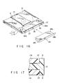
- An indication label 28 having first to third rectangular indication surfaces 28a, 28b, and 28c is adhered on the first and second label adhering portions 25 and 26 of the cartridge body 11, as shown in FIG. 16.
- the second indication surface 28b is shaped so as to have a longer length dimension than the first and third indication surfaces 28a and 28c, and is positioned with respect to the second label adhering portion 26 in such a manner that three edges of each side projecting portion of the indication surface 28b are matched with the corresponding position limit portion 26a of the second label adhering portion 26.
- first and third indication surfaces 28a and 28c of the indication label 28 are adhered onto the first label adhering portions 25 such that the end portions of these surfaces respectively correspond to the end portions of the first label adhering portions 25 of the upper and lower casings 11a and 11b.
- the position limit portions 26a of the second label adhering portion 26 may be formed such that the position limit portions 26a define at least two end edges of the indication surface 28b of the indication label 28.
- the indication label 28 thus adhered on the first and second label adhering portions 25 and 26 can be easily divided into first to third indication surfaces 28a to 28c, by tracing the label separate grooves 27 of the cartridge body 11 with use of a tool such as a pen or the like. Therefore, the indication label 28 adhered on the first and second label adhering portions 25 and 26 can easily be replaced partially, in units of first to third indication surfaces 28a to 28c. As a result of this, when information in the optical disc 12 is over-written or so, the label can be easily replaced in such a manner in which replacement of a current indication label does not affects records on the current indication label.
- the indication label 28 is adhered on a base sheet 33 with an adhesion applied on the back surface of the label, such that the label can be pealed off from the sheet, as shown in FIGS. 18A to 18D.
- FIGS. 18A to 18D In case of the indication label 28 shown in FIG. 18A, boundaries between first to third indication surfaces 28a to 28c are not processed. However, perforation-like cutting guide lines (FIG. 18B) may be formed at a predetermined distance maintained therebetween, or cutting guide lines (FIG. 18C) continuously extending in the widthwise direction to the middle area of the boundaries may be formed on the boundaries, so that first to third indication surfaces can be separated from each other upon requests after the indication label 28 is adhered on the cartridge body 11. In this manner, handling ability of the label can be improved when adhering labels.
- indication labels 29a to 29c each having one single indication surface may be independently adhered on the first and second label adhering portions 25 and 26 of the cartridge. Then, the adhering area of the second label adhering portion 26 of the lid member 10 in the rear end side of the cartridge body 11 can particularly be enlarged, so that the indication contents can achieve a high degree of freedom. In this case, the indication labels 29a to 29c are independently adhered on the base sheet, as shown in FIG. 18D.
- the shutter 9 When the disc cartridge constructed as described above is loaded into a disc recording/reproducing device not shown along the insert direction E shown in FIG. 1, the shutter 9 is slid toward an end side (to the left or right) at first by the shutter opening/closing means in the device, and the opening portion 13 is thereby opened. Then, a turn table not shown enters through the opening portion 13 into the cartridge body 11 to rotatably support the optical disc 12 while a pick-up faces one surface of the optical disc 12 through the opening portion 13.
- the optical disc 12 is rotated by the turn-table, and information signals are recorded on and/or reproduced from the optical disc 12 by the pick-up.
- the first or second write protect operating portion 19 or 20 must be previously set to the write allowable position.
- the lock claw 16 of the lid member 10 is pushed against the elasticity of itself, so as to leave the engage hole 17, and the lid member is rotated in the arrow direction D. Then, the disc 12 stored in the disc storing portion 15 of the cartridge body 11 is guided along the disc guide groove portion 18 of the lid member 10, passing through the disc inlet/outlet port 14, so that extraction of the disc is enabled. In this state, the lid member 10 bends and removes away the open/close detect pin 23 provided in the lower casing 11b of the cartridge body 11, in association with its rotation, thereby indicating that the lid member 10 has been opened so that the disc can be extracted.
- This lid member 10 closes the disc inlet/outlet port 14 when the lid member 10 is rotated in the arrow direction C from its open position.
- the lock claw 16 is elastically engaged with the engage hole 17, and the lid member 10 securely closes the disc inlet/outlet port 14, while being kept in contact with the rear end surface of the cartridge body 11 by the elastic force of the lid member itself.
- the lid member 10 is provided on an end portion of the disc inlet/outlet port 14 of the cartridge body 11, at one end of the lid member and a clearance M is formed between the other end portion of the lid member and the corresponding abutting surface of the cartridge body 11, where the disc inlet/outlet port 14 is kept closed.
- the lock claw 16 is elastically engaged with engage hole 17 of the cartridge body 11 and the lid member is locked on the closed position of the disc inlet/outlet port 14, by pushing the other end portion of the lid member 10 in the closing direction by the clearance M, with the disc inlet/outlet port 14 of the cartridge body 11 kept closed.
- the position arrangement of the lock claw 16 of the lid member 10 and the engage hole 17 of the cartridge body 11 can be realized in form of a highly precise elastic engagement using the clearance M, without particularly providing an operation margin (for an over-stroke). Therefore, the lid member does not cause backlash in the closed position, but securely closes the disc inlet/outlet port 14 of the cartridge body 11.
- the lid member 10 is carried out with a high reliability, with respect to the cartridge body 11 storing the optical disc 12.
- the optical disc can be extracted for the purpose of single use of the disc while ensuring the disc cartridge structure that the optical disc 12 is contained in the cartridge body 11. The degree of freedom in use of discs can thus be improved.
- the present invention is not limited to the above embodiment, but can be variously modified within the scope of the present invention.
- the above explanation has been made to an embodiment applied to the optical disc 12 having data recording surfaces on both sides.
- the present invention is not limited thereto but can be applied to such a disc 12 which has a data recording surface on only one side.
- the recording medium is not limited to the optical disc, but any other kind of disc-like recording medium such as a the magnetic disc, a magneto-optical disc, or the like is applicable.
- the clearance M defined between the end surface of the cartridge body 11 and the fringe 8 of the lid member 10 is not limited to the structure of using slanting surfaces 8a formed on the lid member or on the cartridge body, but may be realized by a structure using steps.
- the lock claw 16 as an elastic engagement portion is provided in the lid member 10 and the engage hole 17 is formed in the cartridge body 11.
- the engage hole may be formed in the lid member 10 while the lock claw is provided on the cartridge body 11, inversely.
- the disc inlet/outlet port 14 which is closed and opened by the lid member is provided at that end face of the cartridge body 11 which is opposite to the opening portions 13 of the cartridge body 11, but the disc inlet/outlet port 14 may be provided at another end face of the cartridge body except for the end face of the cartridge body where the opening portion 13 is provided.
Landscapes
- Packaging For Recording Disks (AREA)
- Packaging Of Annular Or Rod-Shaped Articles, Wearing Apparel, Cassettes, Or The Like (AREA)
- Feeding And Guiding Record Carriers (AREA)
Claims (9)
- Plattenkassette, umfassend:dadurch gekennzeichnet, daßeinen Kassettenkörper (11) zum Unterbringen eines drehbar gehaltenen, plattenartigen Aufzeichnungsträgers (12), wobei der Kassettenkörper (11) einen Öffnungsteil (13) zum Exponieren eines Teils einer Oberfläche des Aufzeichnungsträgers sowie eine Platten-Einlaß-/Auslaßöffnung (14) zum Einlegen und Herausnehmen des Aufzeichnungsträgers aufweist,ein gleitfähig am Kassettenkörper (11) angebrachtes Verschlußteil (9) zum Öffnen/Verschließen des Öffnungsabschnitts (13),ein am Kassettenkörper (11) so angebrachtes Deckelelement (10), daß es zwischen einer Verschlußstellung, in der das Deckelelement (10) die Platten-Einlaß-/Auslaßöffnung (14) verschließt, und einer Öffnungsstellung, in der das Deckelelement (10) die Platten-Einlaß/Auslaßöffnung (14) öffnet, drehbar ist, wobei das Deckelelement (10) einen ersten, drehbar am Kassettenkörper (11) gelagerten Endabschnitt und einen zweiten, drehbar um den ersten Endabschnitt gelagerten Endabschnitt aufweist, und der Kassettenkörper (11) einen Anlageabschnitt zum Anlegen gegen das Deckelelement (10) aufweist, wenn das Deckelelement (10) in die Verschlußstellung gedreht wird bzw. ist, sowieEingriffsmittel (16,17) zum lösbaren Verriegeln des zweiten Endabschnitts des Deckelelements (10) gegenüber dem Kassettenkörper (11), um das Deckelelement (10) in der Verschlußstellung zu halten,der zweite Endabschnitt des Deckelelements (10) dem Anlageabschnitt des Kassettenkörpers (11) in der Verschlußstellung mit einem Abstand (M) dazwischen gegenüberliegt, unddas Eingriffsmittel (16,17) zum lösbaren Verriegeln des zweiten Endabschnitts des Deckelelements (10) gegenüber dem Kassettenkörper (11) das Deckelelement (10) in der Verschlußstellung hält, wenn der in der Verschlußstellung positionierte zweite Endabschnitt des Deckelelements (10) elastisch in einer Richtung zum Anlageabschnitt hin verformt wird, um den Abstand bzw. Zwischenraum (M) zu eliminieren.
- Plattenkassette nach Anspruch 1, dadurch gekennzeichnet, daß der zweite Endabschnitt eine Schrägfläche (8a) aufweist, welche schräg zum Anlageabschnitt ist und den Abstand (M) zwischen der Schrägfläche (8a) und dem Anlageabschnitt festlegt.
- Plattenkassette nach Anspruch 2, dadurch gekennzeichnet, daß sich die Schrägfläche (8a) zum zweiten Endabschnitt von einem Mittelbereich zwischen dem ersten und dem zweiten Endabschnitt des Deckelelements (10) erstreckt.
- Plattenkassette nach Anspruch 3, dadurch gekennzeichnet, daß das Deckelelement (10) einen Deckelkörper, der in der Verschlußstellung in die Platten-Einlaß-/Auslaßöffnung (14) eintritt, aufweist, sowie einen vom Deckelkörper abstehenden Randsteg (8) zum Anlegen gegen den Anlageabschnitt des Kassettenkörpers (11) in der Verschlußstellung, wobei der Randsteg (8) die Schrägfläche (8a) aufweist.
- Plattenkassette, nach Anspruch 1, dadurch gekennzeichnet, daß der Anlageabschnitt des Kassettenkörpers (11) eine Schrägfläche (11e) aufweist, welche dem zweiten Endabschnitt des Deckelelements (10) schräg gegenüberliegt und den Zwischenraum bzw. Abstand (M) zwischen dem Anlageabschnitt und dem zweiten Endabschnitt festlegt.
- Plattenkassette nach Anspruch 1, 2, 3 oder 5,
dadurch gekennzeichnet, daß das Eingriffsmittel ein in dem Kassettenkörper ausgebildetes Eingriffsloch (17), sowie eine am zweiten Endabschnitt des Deckelelements (10) vorgesehene Eingriffsklaue (16) umfaßt, die elastisch und trennbar mit dem Eingriffsloch (17) in Eingriff steht, wenn der zweite Endabschnitt des Deckelelements (10) elastisch in der Richtung verformt wird, in der der Abstand (M) eliminiert ist bzw. wird. - Plattenkassette nach Anspruch 6, dadurch gekennzeichnet, daß das Deckelelement (10) einen Deckelkörper aufweist, der in der Verschlußstellung in die Platten-Einlaß/Auslaßöffnung (14) hineinragt, sowie einen vom Deckelkörper zur Anlage gegen den Anlageabschnitt des Plattenkörpers (11) in der Verschlußstellung abstehenden Randsteg (8), wobei die Eingriffsklaue (16) am Deckelkörper ausgebildet ist.
- Plattenkassette nach einem der Ansprüche 1 bis 7, dadurch gekennzeichnet, daß das Deckelelement (10) eine andere Farbe als der Kassettenkörper (11) aufweist.
- Plattenkassette nach einem der Ansprüche 1 bis 8, dadurch gekennzeichnet, daß das Deckelelement einen Anschlag (7) zum elastischen Anlegen gegen den aus der Platten-Einlaß/Auslaßöffnung (14) herausgenommenen Aufzeichnungsträger (12) aufweist, um ein plötzliches Herausfallen des Aufzeichnungsträgers in der Verschlußstellung des Deckelelements (10) zu verhindern.
Applications Claiming Priority (2)
| Application Number | Priority Date | Filing Date | Title |
|---|---|---|---|
| JP26585795A JP3462318B2 (ja) | 1995-10-13 | 1995-10-13 | ディスクカートリッジ装置 |
| JP265857/95 | 1995-10-13 |
Publications (2)
| Publication Number | Publication Date |
|---|---|
| EP0768662A1 EP0768662A1 (de) | 1997-04-16 |
| EP0768662B1 true EP0768662B1 (de) | 1999-03-10 |
Family
ID=17423056
Family Applications (1)
| Application Number | Title | Priority Date | Filing Date |
|---|---|---|---|
| EP96116339A Expired - Lifetime EP0768662B1 (de) | 1995-10-13 | 1996-10-11 | Plattenkassette |
Country Status (7)
| Country | Link |
|---|---|
| US (1) | US5748609A (de) |
| EP (1) | EP0768662B1 (de) |
| JP (1) | JP3462318B2 (de) |
| KR (1) | KR100274517B1 (de) |
| CN (1) | CN1147859C (de) |
| DE (1) | DE69601687T2 (de) |
| TW (1) | TW347531B (de) |
Families Citing this family (24)
| Publication number | Priority date | Publication date | Assignee | Title |
|---|---|---|---|---|
| US5991260A (en) | 1995-02-20 | 1999-11-23 | Hitachi, Ltd. | Disk cartridge and disk device using the same |
| JP3594314B2 (ja) * | 1995-09-21 | 2004-11-24 | 松下電器産業株式会社 | ディスク取り出し可能なディスクカートリッジ |
| US6075765A (en) * | 1995-11-17 | 2000-06-13 | Hitachi, Ltd. | Information recording and reproducing apparatus, a cartridge for use in the same, and an information recording and reproducing system having the apparatus |
| JP3666111B2 (ja) * | 1996-03-21 | 2005-06-29 | ソニー株式会社 | 円盤状光記録媒体 |
| JP3491118B2 (ja) * | 1996-03-28 | 2004-01-26 | 日立マクセル株式会社 | ディスクカートリッジ |
| JPH1064237A (ja) * | 1996-08-20 | 1998-03-06 | Toshiba Corp | 情報記憶媒体のカートリッジ装置 |
| US6507560B2 (en) | 1998-04-28 | 2003-01-14 | Hitachi, Ltd. | Disc cartridge |
| SG81273A1 (en) * | 1998-04-28 | 2001-06-19 | Hitachi Ltd | Disc cartridge |
| SG94718A1 (en) * | 1998-05-23 | 2003-03-18 | Samsung Electronics Co Ltd | Cartridge for an information recording medium |
| BE1012279A3 (fr) | 1998-11-18 | 2000-08-01 | Staar Sa | Boitiers pour support de donnees. |
| JP2001057048A (ja) * | 1999-03-05 | 2001-02-27 | Hitachi Maxell Ltd | ディスクカートリッジ |
| US6577592B1 (en) * | 1999-04-30 | 2003-06-10 | Sony Corporation | Disc cartridge |
| EP1178488B1 (de) * | 1999-06-04 | 2008-01-09 | Matsushita Electric Industrial Co., Ltd. | Plattenkassette |
| US6580683B1 (en) | 1999-06-23 | 2003-06-17 | Dataplay, Inc. | Optical recording medium having a master data area and a writeable data area |
| US7227817B1 (en) | 1999-12-07 | 2007-06-05 | Dphi Acquisitions, Inc. | Low profile optical head |
| US6631359B1 (en) | 1999-09-10 | 2003-10-07 | Dphi Acquisitions, Inc. | Writeable medium access control using a medium writeable area |
| US7191153B1 (en) | 1999-09-10 | 2007-03-13 | Dphi Acquisitions, Inc. | Content distribution method and apparatus |
| TW464038U (en) * | 1999-10-11 | 2001-11-11 | Ritek Corp | Cassette for protecting optical recorded medium |
| JP2005116081A (ja) * | 2003-10-08 | 2005-04-28 | Sony Corp | ディスクカートリッジ |
| US7382571B2 (en) * | 2004-08-09 | 2008-06-03 | Seagate Technology Llc | Pressure equalizing fluid flow stripper apparatus |
| US8885288B2 (en) * | 2007-12-15 | 2014-11-11 | Seagate Technology Llc | Shrouding a data storage disc with disc facing surfaces that define protuberant features |
| CN102117101B (zh) * | 2009-12-31 | 2013-12-11 | 鸿富锦精密工业(深圳)有限公司 | 笔记本电脑 |
| JP5707736B2 (ja) * | 2010-05-25 | 2015-04-30 | ソニー株式会社 | ディスクカートリッジ |
| KR101532185B1 (ko) * | 2011-07-29 | 2015-06-26 | 미쓰비시덴키 가부시키가이샤 | 인코더 |
Family Cites Families (24)
| Publication number | Priority date | Publication date | Assignee | Title |
|---|---|---|---|---|
| US3500364A (en) * | 1967-03-02 | 1970-03-10 | Disc Pack Corp | Disc pack with card label |
| JPS606930Y2 (ja) * | 1981-06-01 | 1985-03-07 | 日本ビクター株式会社 | 円盤状情報記録媒体用カ−トリツジ |
| US4737876A (en) * | 1983-05-19 | 1988-04-12 | Verbatim Corporation | Write protect device for a record disk assembly |
| US4669078A (en) * | 1984-07-04 | 1987-05-26 | Nippon Gakki Seizo Kabushiki Kaisha | Disc case |
| US4618061A (en) * | 1984-10-12 | 1986-10-21 | Sequence | Device for protection of digital data |
| US4843511A (en) * | 1985-09-27 | 1989-06-27 | Polaroid Corporation | Magnetic disk cassette having internal biasing ribs |
| US4805061A (en) * | 1987-06-09 | 1989-02-14 | Verbatim Corp. | Self-positioning write protect mechanism for a cartridge |
| US4837652A (en) * | 1987-06-11 | 1989-06-06 | Kerby Thomas D | Method and apparatus for indexing and labeling electronic disks |
| CA1328015C (en) * | 1988-03-11 | 1994-03-22 | Shuji Haruna | Disk cartridge |
| NL8800820A (nl) * | 1988-03-31 | 1989-10-16 | Philips Nv | Cassette. |
| JPH0268378U (de) * | 1988-11-11 | 1990-05-23 | ||
| JPH0292887U (de) * | 1988-12-29 | 1990-07-24 | ||
| JP2827332B2 (ja) * | 1989-10-06 | 1998-11-25 | ソニー株式会社 | ディスクカートリッジ |
| JP2785212B2 (ja) * | 1989-11-14 | 1998-08-13 | ソニー株式会社 | ディスクカートリッジ |
| US5166922A (en) * | 1990-01-29 | 1992-11-24 | Dai Nippon Insatsu Kabushiki Kaisha | Disk cartridge |
| JP2576844Y2 (ja) * | 1991-11-01 | 1998-07-16 | ティーディーケイ株式会社 | ディスクカートリッジ |
| US5390515A (en) * | 1993-01-25 | 1995-02-21 | Alpha Enterprises, Inc. | Security container and release key therefor |
| US5381402A (en) * | 1993-07-07 | 1995-01-10 | Digital Equipment Corporation | Removable disk cartridge for use with a rotary actuated disk drive |
| TW238381B (en) * | 1993-10-29 | 1995-01-11 | Ibm | Optical data storage cartridge system |
| US5417324A (en) * | 1994-04-08 | 1995-05-23 | Joyce Development Corporation | Clear molded thermoplastic compact disc supporting tray |
| US5499233A (en) * | 1994-06-20 | 1996-03-12 | International Business Machines Corporation | Optical disk carrier with write-protect mechanism |
| US5421950A (en) * | 1994-08-12 | 1995-06-06 | Rimage Corporation | Label applicator |
| US5539600A (en) * | 1994-10-07 | 1996-07-23 | Verbatim Corporation | Write protection for memory diskettes |
| US5581540A (en) * | 1995-02-08 | 1996-12-03 | International Business Machines Corporation | Single disk write protection system for multiple-disk cartridge |
-
1995
- 1995-10-13 JP JP26585795A patent/JP3462318B2/ja not_active Expired - Fee Related
-
1996
- 1996-10-11 CN CNB961217065A patent/CN1147859C/zh not_active Expired - Fee Related
- 1996-10-11 US US08/730,295 patent/US5748609A/en not_active Expired - Fee Related
- 1996-10-11 DE DE69601687T patent/DE69601687T2/de not_active Expired - Fee Related
- 1996-10-11 EP EP96116339A patent/EP0768662B1/de not_active Expired - Lifetime
- 1996-10-11 KR KR1019960046118A patent/KR100274517B1/ko not_active IP Right Cessation
- 1996-11-02 TW TW085113385A patent/TW347531B/zh not_active IP Right Cessation
Also Published As
| Publication number | Publication date |
|---|---|
| DE69601687T2 (de) | 1999-10-07 |
| CN1159045A (zh) | 1997-09-10 |
| EP0768662A1 (de) | 1997-04-16 |
| JP3462318B2 (ja) | 2003-11-05 |
| CN1147859C (zh) | 2004-04-28 |
| TW347531B (en) | 1998-12-11 |
| US5748609A (en) | 1998-05-05 |
| JPH09106644A (ja) | 1997-04-22 |
| KR100274517B1 (ko) | 2001-01-15 |
| DE69601687D1 (de) | 1999-04-15 |
| KR970023267A (ko) | 1997-05-30 |
Similar Documents
| Publication | Publication Date | Title |
|---|---|---|
| EP0768662B1 (de) | Plattenkassette | |
| EP0768664B1 (de) | Plattenkassette | |
| EP0768665B1 (de) | Plattenkassette | |
| EP0669617B1 (de) | Disc-Kassette mit Verschluss | |
| EP0376570B2 (de) | Datenspeicherkassette mit einer Schreib-Schutz-Anordnung | |
| US5867476A (en) | Cartridge adaptor and a cartridge to be accommodated in the cartridge adaptor | |
| JP3178005B2 (ja) | ディスクカートリッジ | |
| CA2062100C (en) | Disc cartridge | |
| EP0772196B1 (de) | Plattenkassette | |
| EP0771004B1 (de) | Plattenkassette | |
| US5367422A (en) | Disc cartridge having mistaken recording inhibiting mechanism | |
| EP0768663B1 (de) | Plattenkassette und Etikett dafür | |
| EP0843310A1 (de) | Plattenkassette | |
| EP1122731A2 (de) | Einrichtung für Plattenkassette | |
| US6002557A (en) | Disc cartridge with opening detector | |
| US6052359A (en) | Disk cartridge having a dynamically stable supported member in a discrimination hole | |
| JP3481040B2 (ja) | ディスクカートリッジ | |
| CA2303117A1 (en) | Cartridge housing provided with a protrusion to prevent improper insertion | |
| KR100875316B1 (ko) | 정보 기록 매체 카트리지 | |
| JP4362879B2 (ja) | ディスクカートリッジ | |
| JP3485761B2 (ja) | ディスクカートリッジ | |
| JP3257557B2 (ja) | 記録及び/又は再生装置 | |
| CA2077982C (en) | Disc cartridge having mistaken recording inhibiting mechanism | |
| JPH097345A (ja) | 磁気ディスクカートリッジ | |
| JPH06215465A (ja) | 光ディスク装置 |
Legal Events
| Date | Code | Title | Description |
|---|---|---|---|
| PUAI | Public reference made under article 153(3) epc to a published international application that has entered the european phase |
Free format text: ORIGINAL CODE: 0009012 |
|
| 17P | Request for examination filed |
Effective date: 19961108 |
|
| AK | Designated contracting states |
Kind code of ref document: A1 Designated state(s): DE FR GB NL |
|
| 17Q | First examination report despatched |
Effective date: 19970318 |
|
| GRAG | Despatch of communication of intention to grant |
Free format text: ORIGINAL CODE: EPIDOS AGRA |
|
| GRAG | Despatch of communication of intention to grant |
Free format text: ORIGINAL CODE: EPIDOS AGRA |
|
| GRAH | Despatch of communication of intention to grant a patent |
Free format text: ORIGINAL CODE: EPIDOS IGRA |
|
| GRAH | Despatch of communication of intention to grant a patent |
Free format text: ORIGINAL CODE: EPIDOS IGRA |
|
| GRAA | (expected) grant |
Free format text: ORIGINAL CODE: 0009210 |
|
| AK | Designated contracting states |
Kind code of ref document: B1 Designated state(s): DE FR GB NL |
|
| REF | Corresponds to: |
Ref document number: 69601687 Country of ref document: DE Date of ref document: 19990415 |
|
| ET | Fr: translation filed | ||
| PLBE | No opposition filed within time limit |
Free format text: ORIGINAL CODE: 0009261 |
|
| STAA | Information on the status of an ep patent application or granted ep patent |
Free format text: STATUS: NO OPPOSITION FILED WITHIN TIME LIMIT |
|
| 26N | No opposition filed | ||
| REG | Reference to a national code |
Ref country code: GB Ref legal event code: IF02 |
|
| PGFP | Annual fee paid to national office [announced via postgrant information from national office to epo] |
Ref country code: NL Payment date: 20081005 Year of fee payment: 13 |
|
| PGFP | Annual fee paid to national office [announced via postgrant information from national office to epo] |
Ref country code: DE Payment date: 20081014 Year of fee payment: 13 |
|
| PGFP | Annual fee paid to national office [announced via postgrant information from national office to epo] |
Ref country code: FR Payment date: 20081014 Year of fee payment: 13 |
|
| PGFP | Annual fee paid to national office [announced via postgrant information from national office to epo] |
Ref country code: GB Payment date: 20081008 Year of fee payment: 13 |
|
| REG | Reference to a national code |
Ref country code: NL Ref legal event code: V1 Effective date: 20100501 |
|
| REG | Reference to a national code |
Ref country code: FR Ref legal event code: ST Effective date: 20100630 |
|
| PG25 | Lapsed in a contracting state [announced via postgrant information from national office to epo] |
Ref country code: NL Free format text: LAPSE BECAUSE OF NON-PAYMENT OF DUE FEES Effective date: 20100501 Ref country code: FR Free format text: LAPSE BECAUSE OF NON-PAYMENT OF DUE FEES Effective date: 20091102 Ref country code: DE Free format text: LAPSE BECAUSE OF NON-PAYMENT OF DUE FEES Effective date: 20100501 |
|
| PG25 | Lapsed in a contracting state [announced via postgrant information from national office to epo] |
Ref country code: GB Free format text: LAPSE BECAUSE OF NON-PAYMENT OF DUE FEES Effective date: 20091011 |