EP0768286A1 - Horizontal paddle type fermentation system and method of operating the same - Google Patents
Horizontal paddle type fermentation system and method of operating the same Download PDFInfo
- Publication number
- EP0768286A1 EP0768286A1 EP19950120596 EP95120596A EP0768286A1 EP 0768286 A1 EP0768286 A1 EP 0768286A1 EP 19950120596 EP19950120596 EP 19950120596 EP 95120596 A EP95120596 A EP 95120596A EP 0768286 A1 EP0768286 A1 EP 0768286A1
- Authority
- EP
- European Patent Office
- Prior art keywords
- fermenter
- raw material
- stirrer
- fermentation system
- paddle wheel
- Prior art date
- Legal status (The legal status is an assumption and is not a legal conclusion. Google has not performed a legal analysis and makes no representation as to the accuracy of the status listed.)
- Granted
Links
Images


Classifications
-
- C—CHEMISTRY; METALLURGY
- C05—FERTILISERS; MANUFACTURE THEREOF
- C05F—ORGANIC FERTILISERS NOT COVERED BY SUBCLASSES C05B, C05C, e.g. FERTILISERS FROM WASTE OR REFUSE
- C05F17/00—Preparation of fertilisers characterised by biological or biochemical treatment steps, e.g. composting or fermentation
- C05F17/90—Apparatus therefor
- C05F17/964—Constructional parts, e.g. floors, covers or doors
- C05F17/971—Constructional parts, e.g. floors, covers or doors for feeding or discharging materials to be treated; for feeding or discharging other material
-
- C—CHEMISTRY; METALLURGY
- C05—FERTILISERS; MANUFACTURE THEREOF
- C05F—ORGANIC FERTILISERS NOT COVERED BY SUBCLASSES C05B, C05C, e.g. FERTILISERS FROM WASTE OR REFUSE
- C05F17/00—Preparation of fertilisers characterised by biological or biochemical treatment steps, e.g. composting or fermentation
- C05F17/90—Apparatus therefor
- C05F17/921—Devices in which the material is conveyed essentially horizontally between inlet and discharge means
- C05F17/939—Means for mixing or moving with predetermined or fixed paths, e.g. rails or cables
-
- C—CHEMISTRY; METALLURGY
- C05—FERTILISERS; MANUFACTURE THEREOF
- C05F—ORGANIC FERTILISERS NOT COVERED BY SUBCLASSES C05B, C05C, e.g. FERTILISERS FROM WASTE OR REFUSE
- C05F17/00—Preparation of fertilisers characterised by biological or biochemical treatment steps, e.g. composting or fermentation
- C05F17/90—Apparatus therefor
- C05F17/964—Constructional parts, e.g. floors, covers or doors
-
- Y—GENERAL TAGGING OF NEW TECHNOLOGICAL DEVELOPMENTS; GENERAL TAGGING OF CROSS-SECTIONAL TECHNOLOGIES SPANNING OVER SEVERAL SECTIONS OF THE IPC; TECHNICAL SUBJECTS COVERED BY FORMER USPC CROSS-REFERENCE ART COLLECTIONS [XRACs] AND DIGESTS
- Y02—TECHNOLOGIES OR APPLICATIONS FOR MITIGATION OR ADAPTATION AGAINST CLIMATE CHANGE
- Y02P—CLIMATE CHANGE MITIGATION TECHNOLOGIES IN THE PRODUCTION OR PROCESSING OF GOODS
- Y02P20/00—Technologies relating to chemical industry
- Y02P20/141—Feedstock
- Y02P20/145—Feedstock the feedstock being materials of biological origin
-
- Y—GENERAL TAGGING OF NEW TECHNOLOGICAL DEVELOPMENTS; GENERAL TAGGING OF CROSS-SECTIONAL TECHNOLOGIES SPANNING OVER SEVERAL SECTIONS OF THE IPC; TECHNICAL SUBJECTS COVERED BY FORMER USPC CROSS-REFERENCE ART COLLECTIONS [XRACs] AND DIGESTS
- Y02—TECHNOLOGIES OR APPLICATIONS FOR MITIGATION OR ADAPTATION AGAINST CLIMATE CHANGE
- Y02W—CLIMATE CHANGE MITIGATION TECHNOLOGIES RELATED TO WASTEWATER TREATMENT OR WASTE MANAGEMENT
- Y02W30/00—Technologies for solid waste management
- Y02W30/40—Bio-organic fraction processing; Production of fertilisers from the organic fraction of waste or refuse
Definitions
- the present invention relates to a horizontal paddle type fermentation system and, more particularly, to a horizontal paddle type fermentation system which efficiently mixes, breaks up and transfers organic substances such as crushed refuse, sludge, dung, etc., and which, while doing so, causes such organic substances to ferment by the action of microorganisms, thereby composting the organic substances.
- the present invention also relates to a method of operating the horizontal paddle type fermentation system.
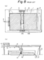
- Figs. 8(a) and 8(b) show a conventional horizontal paddle type fermentation system.
- Crushed refuse or the like as a raw material is introduced into a fermenter 1, which is the hatched part in the figure, from an inlet 4.
- a stirrer 2 with a rotary paddle wheel 13 is caused to repeat longitudinal travel motion and lateral traverse motion in the fermenter 1 by the action of a travel gear 3, thereby turning the raw material, that is, stirring and moving it.
- the travel gear 3 travels on rails 12b.
- the travel gear 3, which is equipped with rails 12a and the stirrer 2 moves on the rails 12b.
- the stirrer 2 moves on the rails 12a provided on the travel gear 3.
- the paddle wheel 13, which is provided on the stirrer 2 rotates in the direction of the arrow shown in Fig. 8(b).
- Fig. 9 shows the way in which the raw material is turned, i.e. stirred and moved, by the rotation of the paddle wheel 13.
- reference symbol A denotes the direction of progress of the paddle wheel 13
- B the direction of rotation of the paddle wheel 13
- C the direction of movement of the raw material
- D the scattering loci of the raw material. That is, as the paddle wheel 13, which has blades with hooked tips, rotates forward, the raw material lying in the progress direction of the paddle wheel 13 scatters in the direction opposite to the paddle wheel progress direction, drawing the loci D. Accordingly, if the travel gear 3 stops the longitudinal travel motion in the state shown in Fig.
- the raw material introduced into the fermenter 1 through the inlet 4 is successively moved rightward as viewed in the drawing, and taken out of the fermenter 1 through an outlet 5. Meanwhile, the raw material is gradually composted by fermentation.
- the raw material By the action of turning the raw material performed by the paddle wheel 13 as described above, the raw material is favorably ventilated, and uniform ventilation is effected in the entire fermenter 1.
- the raw material is composted by aerobic fermentation under the effect of microorganisms.
- “turning” means that the raw material is satisfactorily mixed by the rotation of the paddle wheel 13, and that the introduced raw material is successively transferred from the inlet side to the outlet side by the scattering action of the paddle wheel 13.
- the turning is a requisite for a fermenter which composts organic matter by fermentation.
- the stirrer 2 in the prior art is designed to transfer the raw material from the left side of the stirrer 2, as viewed in the drawing, to the right side by the scattering action of the paddle wheel 13. Therefore, the travel gear 3 usually starts from the right end (outlet side) of the fermenter 1 and successively moves toward the left end (inlet side).
- the travel gear 3 reaches the left top end (end point) of the fermenter 1, as viewed in Fig. 8(a)
- a return door 7 opens, and the stirrer 2 returns to the travel start point at the right end of the fermenter 1 through a passage 8. Then, the stirrer 2 restarts the turning operation throughout the fermenter 1.
- the locus K of movement of the stirrer 2 in the conventional system will be explained below with reference to Fig. 10.
- the stirrer 2 enters an outlet part PA of the fermenter 1 through the passage 8.
- the paddle wheel 13 of the stirrer 2 is started to rotate.
- a zigzag operation of the stirrer 2 in which traversing and traveling of the stirrer 2 are repeated, is carried out in the fermenter 1 from the outlet (5) side toward the raw material inlet (4) side.
- the zigzag operation all the raw material in the fermenter 1 is turned. That is, transfer and stirring of the raw material are attained simultaneously.
- the zigzag operation is completed as the stirrer 2 reaches the passage end PB (end point) at the inlet (4) side of the fermenter 1. Thereafter, the lateral movement of the stirrer 2 and the rotation of the paddle wheel 13 are stopped in front of the return door 7, which is installed between the fermenter 1 and the passage 8 and normally closed to prevent the raw material from overflowing into the passage 8.
- Fig. 11 is a sectional side view of the above-described conventional fermentation system, including the building thereof.
- the conventional horizontal paddle type fermentation system needs the passage 8 for the stirrer 2 to move from the inlet (4) side to the outlet (5) side of the fermenter 1 via the return door 7, and the return door 7 for the stirrer 2 to come out of the fermenter 1 to the passage 8.
- the presence of the return door 7 causes the stirrer 2 to be accompanied by raw material when it comes out of the fermenter 1 to the passage 8. It is therefore necessary to clean the return door area as a maintenance operation.
- the conventional fermentation system requires a humidifier 9 for promoting fermentation of organic matter, and suction hoods 16, a deodorizing fan 17, a deodorizer, etc. for removing the odor produced during fermentation.
- a humidifier 9 for promoting fermentation of organic matter
- suction hoods 16 for promoting fermentation of organic matter
- suction hoods 16 for promoting fermentation of organic matter
- suction hoods 16 for promoting fermentation of organic matter
- suction hoods 16 for a deodorizing fan 17
- a deodorizer, etc. for removing the odor produced during fermentation.
- an object of the present invention is to provide a compact horizontal paddle type fermentation system which is easy to maintain and small in size, and also a method of operating the horizontal paddle type fermentation system.
- the present invention provides a horizontal paddle type fermentation system having a fermenter for composting a raw material stored therein by fermentation, a stirrer with a paddle wheel which stirs and moves the raw material in one direction, thereby turning the raw material, and a travel gear for freely moving the stirrer in the fermenter.
- the fermentation system further has rails for moving the travel gear between a raw material inlet and an outlet, and side walls for covering the fermenter. The rails and the side walls are supported by side walls of the fermenter.
- the paddle wheel has blade tips which are capable of turning the raw material in opposite directions in response to forward and backward rotation of the paddle wheel.
- the present invention is characterized in that the side walls that cover the fermenter and the side walls of the fermenter are integrated with each other, and that support blocks for the rails that support the travel gear are secured to the inner wall surfaces of the integrated side walls.
- the present invention is characterized in that the stirrer is moved to travel through the fermenter from the outlet side toward the inlet side with the paddle wheel rotating forward, thereby stirring and transferring all the raw material in the fermenter in the direction of the outlet, and thereafter, in order to return the stirrer to an operation start point, it is moved to travel through the fermenter from the inlet side toward the outlet side with the paddle wheel rotating backward, thereby turning a part of the raw material in the fermenter in the direction of the inlet.
- the present invention provides a method of operating the horizontal paddle type fermentation system, which is characterized in that a return start point for returning the stirrer to the operation start point in the fermenter is changed for each run, thereby preventing the turning of the raw material in the direction of the inlet from being localized on one region.
- the operating method is further characterized in that a distance through which the stirrer is traversed during the return operation is set in the range of from zero to a distance corresponding to the width of the paddle wheel, thereby defining a range of turning the raw material in the direction of the inlet.
- Fig. 1 is a plan view of one embodiment of the horizontal paddle type fermentation system according to the present invention.
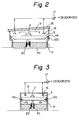
- Fig. 2 is a sectional side view of the fermentation system shown in Fig. 1.
- Fig. 3 is a sectional side view of another embodiment of the horizontal paddle type fermentation system according to the present invention.
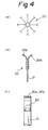
- Figs. 4(a) to 4(c) are views showing the structure of a paddle wheel in one embodiment of the present invention, in which: Fig. 4(a) shows the whole paddle wheel; Fig. 4(b) shows the tip portion of a blade of the paddle wheel; and Fig. 4(c) is a side view of the blade tip.
- Fig. 5(a) illustrates an operation of the paddle wheel, shown in Fig. 4(a), when rotating forward.
- Fig. 5(b) illustrates an operation of the paddle wheel, shown in Fig. 4(a), when rotating backward.
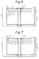
- Fig. 6 illustrates a method of operating the horizontal paddle type fermentation system according to the present invention.
- Fig. 7 illustrates another method of operating the horizontal paddle type fermentation system according to the present invention.
- Figs. 8(a) and 8(b) are plan and front views, respectively, showing a conventional horizontal paddle type fermentation system.
- Fig. 9 illustrates the way in which a raw material is turned by the rotation of a paddle wheel.
- Fig. 10 illustrates a method of operating the conventional fermentation system shown in Figs. 8(a) and 8(b).
- Fig. 11 is a sectional side view of the conventional fermentation system shown in Figs. 8(a) and 8(b).
- Fig. 1 is a plan view of one embodiment of the horizontal paddle type fermentation system according to the present invention.
- a fermenter 1 a raw material such as crushed refuse, sludge, dung, etc. is stored and gradually composted by aerobic fermentation under the effect of microorganisms.
- the raw material is introduced into the fermenter 1 from an inlet 4.
- the raw material is stirred and, at the same time, gradually transferred from the inlet (4) side toward an outlet 5 as well as stirred by a stirrer 2 with a paddle wheel.
- the turning operation allows air to enter the gaps between pieces of the broken raw material, thus enabling fermentation to progress.
- the stirrer 2 performs a zigzag operation in which it repeats a zigzag traverse and travel motion in the fermenter 1, thereby uniformly stirring and transferring all the raw material stored in the fermenter 1 in the same way as in the prior art.
- a travel gear 3 which enables the stirrer 2 to move zigzag is supported by rails 12b, and the rails 12b are respectively supported by longitudinally-extending side walls 1a of the fermenter 1 so as to lie in the neighborhood of the side walls 1a.
- the travel gear 3 bridges the rails 12b on both sides of the fermenter 1, and travels from the outlet (5) side toward the inlet (4) side, thereby turning and transferring the raw material from the inlet (4) side toward the outlet (5) side.
- the rails 12b of the travel gear 3 are supported by the side walls 1a on both sides of the fermenter 1, it is possible to save the space for the passage 8 conventionally used for the stirrer 2 to return to the outlet (5) side from the inlet (4) side.
- Fig. 2 is a sectional side view of the horizontal paddle type fermentation system shown in Fig. 1.
- the rails 12b of the travel gear 3, which is equipped with the stirrer 2 are supported by the side walls 1a of the fermenter 1.
- Side walls 14 of a building that covers the fermenter 1 are also supported by the side walls 1a of the fermenter 1.
- a ceiling 15 that covers the fermenter 1 is secured to the upper ends of the side walls 14 of the building covering the fermenter 1. Accordingly, the building can be made compact in size, and the building production cost can be reduced.
- the fermentation system in this embodiment is also provided with a humidifier 9 for promoting fermentation.
- a humidifier 9 for promoting fermentation.
- the fermentation system is provided with suction hoods 16 and a deodorizing fan 17, together with a deodorizer for preventing secondary environmental pollution which would otherwise be caused by the odor produced in the process of composting.
- suction hoods 16 and a deodorizing fan 17 together with a deodorizer for preventing secondary environmental pollution which would otherwise be caused by the odor produced in the process of composting.
- the deodorizing fan 17 and the deodorizer can be correspondingly reduced.
- Fig. 3 is a sectional side view of another embodiment of the horizontal paddle type fermentation system according to the present invention.
- This embodiment is intended for a small-sized fermenter in comparison to the fermenter 1 in the embodiment shown in Fig. 2.
- the side walls of the fermenter and the side walls covering the fermenter are integrally formed from side wall members 1c. Therefore, the fermentation system does not particularly need side walls for the building.
- a ceiling panel 1d of the fermenter which corresponds to the ceiling of the building that covers the fermenter, is integrated with the side wall members 1c. That is, the fermenter container can be used also as a fermenter building by forming the walls and ceiling of the fermenter from steel plate.
- the rails 12b for supporting the travel gear 3 are supported by respective support blocks 19 which are secured to the inner walls of the fermenter. Accordingly, the fermenter container in this embodiment can be produced as an integral structure in a factory and installed as it is at a desired site. It should be noted that in this embodiment also, the fermentation system is provided with suction hoods 16 and a deodorizing fan 17, and that since the space to be evacuated becomes narrow, the capacities of these devices can be reduced to a considerable extent; this is favorable from the energy-saving point of view.
- Fig. 4(a) shows the structure of a paddle wheel 20 provided on the above-described stirrer.
- Each blade of the paddle wheel 20 in this embodiment has two hooked tips 20a and 20b which are curved away from each other so that the paddle wheel 20 can turn the raw material regardless of whether the paddle wheel 20 rotates forward or backward, that is, the paddle wheel 20 can stir and transfer the raw material in either of the opposite directions.
- Fig. 4(b) is an enlarged view of the blade tip portion
- Fig. 4(c) is a side view of the blade tip portion. That is, a paddle blade tip 20a for forward rotation and a paddle blade tip 20b for backward rotation are secured to the distal end of a rim 21 by nuts and bolts 22.
- Figs. 5(a) and 5(b) show the operation of the paddle wheel 20 having the blade tips 20a and 20b, which are curved in the opposite directions.
- the blade tips 20a turn the raw material, i.e. stir and transfer it toward the outlet side from the inlet side.
- the blade tips 20b scatter the raw material toward the inlet side, thus transferring the raw material from the outlet side to the inlet side.
- the go path of the stirrer that is, the locus of movement of the stirrer during an operation in which it progresses zigzag from the outlet side to the inlet side, repeating traveling and traversing while turning the raw material, is the same as that shown in Fig. 10, which has already been described in regard to the prior art.
- this embodiment has no return passage for the stirrer. Therefore, the stirrer returns to the start point on the outlet side through the fermenter with the paddle wheel rotating backward.
- This method enables the stirrer to be moved through the fermenter 1 from the inlet part to the outlet part without a return door and a passage.
- the layer thickness of the raw material in the fermenter is thin, or when the properties of the raw material are favorable (i.e. the apparent specific gravity is low, and adhesion is weak), it is possible to operate the stirrer without the need of incorporating a traversing pattern.
- the change of the return start point can be readily realized, for example, by a method in which the travel position of the stirrer 2 is changed by using a limit switch which is provided on the travel gear 3 of the fermenter 1, or a method in which the traversing time of the stirrer 2 is changed for each run at the inlet part. It should be noted that it is preferable from the viewpoint of preventing undesired residence of the raw material to set the distance through which the stirrer is traversed during the return operation in the range of from zero to a distance corresponding to the width of the paddle wheel, thereby defining a range of turning the raw material in the direction of the inlet.
- the horizontal paddle type fermentation system used in this embodiment had a stirrer (paddle width: 1.1 m) with a paddle diameter of 1.6 m and a fermenter with a width of 9 m and a length of 20 m.
- a stirrer (paddle width: 1.1 m) with a paddle diameter of 1.6 m and a fermenter with a width of 9 m and a length of 20 m.
- an experiment was carried out using crushed refuse under the condition that the layer thickness of the raw material when introduced was 1.6 m.
- the stirrer was run from the inlet part to the outlet part with the traversing distance set at 1.1 m, it was possible to perform a smooth operation without overload of an electric motor for driving the stirrer.
- stirrer was run by traveling only, with the traversing distance set at 0 m. In that case, piles of raw material frequently crumbled at the sides of the stirrer, causing overload, thus making it impossible to continue the operation.
- the raw material piling condition was changed so that the layer thickness of the raw material when introduced was 1.0 m, and the stirrer was run with the traversing distance set at 0 m. In that case, no overload occurred, although the current value slightly fluctuated.
- stirrer can be effectively returned through the fermenter by setting the traversing distance in the range of from 0 m to a distance approximately equal to the paddle width.
- the present invention makes it possible to eliminate a return door and a passage which have heretofore been essential for the conventional fermentation systems. Consequently, the width of the fermenter building can be reduced to a value equal to the span of the travel gear, and thus the construction cost can be reduced. Further, since no return door is needed, it becomes unnecessary to carry out inspection and cleaning which have heretofore been necessary to conduct at the return door area, and thus labor for maintenance can be saved to a considerable extent. Furthermore, since the side walls and the ceiling, which cover the fermenter, can be made small and compact in size, the internal volume of the building reduces, thus making it possible to reduce the capacities of the deodorizing fan and other devices and save energy.
- the invention relates to a horizontal paddle type fermentation system comprising:
Landscapes
- Chemical & Material Sciences (AREA)
- Chemical Kinetics & Catalysis (AREA)
- Life Sciences & Earth Sciences (AREA)
- Engineering & Computer Science (AREA)
- Biochemistry (AREA)
- Biotechnology (AREA)
- Health & Medical Sciences (AREA)
- General Chemical & Material Sciences (AREA)
- Microbiology (AREA)
- Molecular Biology (AREA)
- Organic Chemistry (AREA)
- Fertilizers (AREA)
- Processing Of Solid Wastes (AREA)
- Mixers With Rotating Receptacles And Mixers With Vibration Mechanisms (AREA)
Abstract
Description
- The present invention relates to a horizontal paddle type fermentation system and, more particularly, to a horizontal paddle type fermentation system which efficiently mixes, breaks up and transfers organic substances such as crushed refuse, sludge, dung, etc., and which, while doing so, causes such organic substances to ferment by the action of microorganisms, thereby composting the organic substances. The present invention also relates to a method of operating the horizontal paddle type fermentation system.
- Figs. 8(a) and 8(b) show a conventional horizontal paddle type fermentation system. Crushed refuse or the like as a raw material is introduced into a fermenter 1, which is the hatched part in the figure, from an
inlet 4. Astirrer 2 with arotary paddle wheel 13 is caused to repeat longitudinal travel motion and lateral traverse motion in the fermenter 1 by the action of atravel gear 3, thereby turning the raw material, that is, stirring and moving it. During the longitudinal travel motion, thetravel gear 3 travels onrails 12b. Thetravel gear 3, which is equipped withrails 12a and thestirrer 2, moves on therails 12b. During the lateral movement in the fermenter 1, thestirrer 2 moves on therails 12a provided on thetravel gear 3. During the lateral movement of thestirrer 2, thepaddle wheel 13, which is provided on thestirrer 2, rotates in the direction of the arrow shown in Fig. 8(b). - Fig. 9 shows the way in which the raw material is turned, i.e. stirred and moved, by the rotation of the
paddle wheel 13. In the figure, reference symbol A denotes the direction of progress of thepaddle wheel 13, B the direction of rotation of thepaddle wheel 13, C the direction of movement of the raw material, and D the scattering loci of the raw material. That is, as thepaddle wheel 13, which has blades with hooked tips, rotates forward, the raw material lying in the progress direction of thepaddle wheel 13 scatters in the direction opposite to the paddle wheel progress direction, drawing the loci D. Accordingly, if thetravel gear 3 stops the longitudinal travel motion in the state shown in Fig. 8(a), and thestirrer 2 alone traverses from end to end on therails 12a while rotating thepaddle wheel 13, the raw material lying on the left side of the bridge portion of thetravel gear 3 moves to the right side thereof. Then, thetravel gear 3 travels slightly leftward on therails 12b and stops, and thestirrer 2 is caused to traverse on therails 12a. Thus, the raw material lying on the left side of the bridge portion of thetravel gear 3 is scattered beyond thetravel gear 3, thereby being moved to the right side of the bridge portion of thetravel gear 3. By repeating the travel and traverse motions of thetravel gear 3 and thestirrer 2, the raw material introduced into the fermenter 1 through theinlet 4 is successively moved rightward as viewed in the drawing, and taken out of the fermenter 1 through anoutlet 5. Meanwhile, the raw material is gradually composted by fermentation. - By the action of turning the raw material performed by the
paddle wheel 13 as described above, the raw material is favorably ventilated, and uniform ventilation is effected in the entire fermenter 1. Thus, the raw material is composted by aerobic fermentation under the effect of microorganisms. So-called "turning" means that the raw material is satisfactorily mixed by the rotation of thepaddle wheel 13, and that the introduced raw material is successively transferred from the inlet side to the outlet side by the scattering action of thepaddle wheel 13. The turning is a requisite for a fermenter which composts organic matter by fermentation. - As has been described above, the
stirrer 2 in the prior art is designed to transfer the raw material from the left side of thestirrer 2, as viewed in the drawing, to the right side by the scattering action of thepaddle wheel 13. Therefore, thetravel gear 3 usually starts from the right end (outlet side) of the fermenter 1 and successively moves toward the left end (inlet side). When thetravel gear 3 reaches the left top end (end point) of the fermenter 1, as viewed in Fig. 8(a), upon completion of turning of the all raw material in the fermenter 1, areturn door 7 opens, and thestirrer 2 returns to the travel start point at the right end of the fermenter 1 through apassage 8. Then, thestirrer 2 restarts the turning operation throughout the fermenter 1. - The locus K of movement of the
stirrer 2 in the conventional system will be explained below with reference to Fig. 10. First, thestirrer 2 enters an outlet part PA of the fermenter 1 through thepassage 8. At the outlet part PA, thepaddle wheel 13 of thestirrer 2 is started to rotate. Then, a zigzag operation of thestirrer 2, in which traversing and traveling of thestirrer 2 are repeated, is carried out in the fermenter 1 from the outlet (5) side toward the raw material inlet (4) side. By carrying out the zigzag operation, all the raw material in the fermenter 1 is turned. That is, transfer and stirring of the raw material are attained simultaneously. - The zigzag operation is completed as the
stirrer 2 reaches the passage end PB (end point) at the inlet (4) side of the fermenter 1. Thereafter, the lateral movement of thestirrer 2 and the rotation of thepaddle wheel 13 are stopped in front of thereturn door 7, which is installed between the fermenter 1 and thepassage 8 and normally closed to prevent the raw material from overflowing into thepassage 8. - Thereafter, the
return door 7 is opened to allow thestirrer 2 to come out of the fermenter 1. Subsequently, thestirrer 2 laterally moves from the fermenter 1 to thepassage 8. After thestirrer 2 has completely entered thepassage 8, it is moved through thepassage 8 from the inlet side toward the outlet side by thetravel gear 3 and stopped at the start point (PA). Meanwhile, thereturn door 7 is closed. In Fig. 10, reference symbol K denotes the locus of movement of thestirrer 2. - Fig. 11 is a sectional side view of the above-described conventional fermentation system, including the building thereof.
- Thus, the conventional horizontal paddle type fermentation system needs the
passage 8 for thestirrer 2 to move from the inlet (4) side to the outlet (5) side of the fermenter 1 via thereturn door 7, and thereturn door 7 for thestirrer 2 to come out of the fermenter 1 to thepassage 8. In addition, it is necessary to providebuildings passage 8. Since thereturn door 7 and thepassage 8 are required, the size of the whole building (11a and 11b) for accommodating the fermenter 1 is unfavorably large; this restricts the reduction of the construction cost. Further, the presence of thereturn door 7 causes thestirrer 2 to be accompanied by raw material when it comes out of the fermenter 1 to thepassage 8. It is therefore necessary to clean the return door area as a maintenance operation. - Further, the conventional fermentation system requires a
humidifier 9 for promoting fermentation of organic matter, andsuction hoods 16, adeodorizing fan 17, a deodorizer, etc. for removing the odor produced during fermentation. These devices inevitably become large in size because the internal volume of the building is large. - In view of the above-described problems of the prior art, an object of the present invention is to provide a compact horizontal paddle type fermentation system which is easy to maintain and small in size, and also a method of operating the horizontal paddle type fermentation system.
- The present invention provides a horizontal paddle type fermentation system having a fermenter for composting a raw material stored therein by fermentation, a stirrer with a paddle wheel which stirs and moves the raw material in one direction, thereby turning the raw material, and a travel gear for freely moving the stirrer in the fermenter. The fermentation system further has rails for moving the travel gear between a raw material inlet and an outlet, and side walls for covering the fermenter. The rails and the side walls are supported by side walls of the fermenter. The paddle wheel has blade tips which are capable of turning the raw material in opposite directions in response to forward and backward rotation of the paddle wheel.
- In addition, the present invention is characterized in that the side walls that cover the fermenter and the side walls of the fermenter are integrated with each other, and that support blocks for the rails that support the travel gear are secured to the inner wall surfaces of the integrated side walls.
- In addition, the present invention is characterized in that the stirrer is moved to travel through the fermenter from the outlet side toward the inlet side with the paddle wheel rotating forward, thereby stirring and transferring all the raw material in the fermenter in the direction of the outlet, and thereafter, in order to return the stirrer to an operation start point, it is moved to travel through the fermenter from the inlet side toward the outlet side with the paddle wheel rotating backward, thereby turning a part of the raw material in the fermenter in the direction of the inlet.
- In addition, the present invention provides a method of operating the horizontal paddle type fermentation system, which is characterized in that a return start point for returning the stirrer to the operation start point in the fermenter is changed for each run, thereby preventing the turning of the raw material in the direction of the inlet from being localized on one region.
- The operating method is further characterized in that a distance through which the stirrer is traversed during the return operation is set in the range of from zero to a distance corresponding to the width of the paddle wheel, thereby defining a range of turning the raw material in the direction of the inlet.
- Fig. 1 is a plan view of one embodiment of the horizontal paddle type fermentation system according to the present invention.
- Fig. 2 is a sectional side view of the fermentation system shown in Fig. 1.
- Fig. 3 is a sectional side view of another embodiment of the horizontal paddle type fermentation system according to the present invention.
- Figs. 4(a) to 4(c) are views showing the structure of a paddle wheel in one embodiment of the present invention, in which: Fig. 4(a) shows the whole paddle wheel; Fig. 4(b) shows the tip portion of a blade of the paddle wheel; and Fig. 4(c) is a side view of the blade tip.
- Fig. 5(a) illustrates an operation of the paddle wheel, shown in Fig. 4(a), when rotating forward.
- Fig. 5(b) illustrates an operation of the paddle wheel, shown in Fig. 4(a), when rotating backward.
- Fig. 6 illustrates a method of operating the horizontal paddle type fermentation system according to the present invention.
- Fig. 7 illustrates another method of operating the horizontal paddle type fermentation system according to the present invention.
- Figs. 8(a) and 8(b) are plan and front views, respectively, showing a conventional horizontal paddle type fermentation system.
- Fig. 9 illustrates the way in which a raw material is turned by the rotation of a paddle wheel.
- Fig. 10 illustrates a method of operating the conventional fermentation system shown in Figs. 8(a) and 8(b).
- Fig. 11 is a sectional side view of the conventional fermentation system shown in Figs. 8(a) and 8(b).
- One embodiment of the present invention will be described below with reference to Figs. 1 to 7.
- Fig. 1 is a plan view of one embodiment of the horizontal paddle type fermentation system according to the present invention. In a fermenter 1, a raw material such as crushed refuse, sludge, dung, etc. is stored and gradually composted by aerobic fermentation under the effect of microorganisms. The raw material is introduced into the fermenter 1 from an
inlet 4. In the fermenter 1, the raw material is stirred and, at the same time, gradually transferred from the inlet (4) side toward anoutlet 5 as well as stirred by astirrer 2 with a paddle wheel. The turning operation allows air to enter the gaps between pieces of the broken raw material, thus enabling fermentation to progress. Thestirrer 2 performs a zigzag operation in which it repeats a zigzag traverse and travel motion in the fermenter 1, thereby uniformly stirring and transferring all the raw material stored in the fermenter 1 in the same way as in the prior art. - In this embodiment, a
travel gear 3 which enables thestirrer 2 to move zigzag is supported byrails 12b, and therails 12b are respectively supported by longitudinally-extending side walls 1a of the fermenter 1 so as to lie in the neighborhood of the side walls 1a. Thetravel gear 3 bridges therails 12b on both sides of the fermenter 1, and travels from the outlet (5) side toward the inlet (4) side, thereby turning and transferring the raw material from the inlet (4) side toward the outlet (5) side. Thus, since therails 12b of thetravel gear 3 are supported by the side walls 1a on both sides of the fermenter 1, it is possible to save the space for thepassage 8 conventionally used for thestirrer 2 to return to the outlet (5) side from the inlet (4) side. - Fig. 2 is a sectional side view of the horizontal paddle type fermentation system shown in Fig. 1. As will be clear from the figure, the
rails 12b of thetravel gear 3, which is equipped with thestirrer 2, are supported by the side walls 1a of the fermenter 1.Side walls 14 of a building that covers the fermenter 1 are also supported by the side walls 1a of the fermenter 1. Aceiling 15 that covers the fermenter 1 is secured to the upper ends of theside walls 14 of the building covering the fermenter 1. Accordingly, the building can be made compact in size, and the building production cost can be reduced. - The fermentation system in this embodiment is also provided with a
humidifier 9 for promoting fermentation. However, since the space in the building is narrower than in the prior art by at least an amount corresponding to the space for thepassage 8, a smaller-sized humidifier can satisfactorily function as thehumidifier 9. Further, in this embodiment also, the fermentation system is provided withsuction hoods 16 and adeodorizing fan 17, together with a deodorizer for preventing secondary environmental pollution which would otherwise be caused by the odor produced in the process of composting. However, since the internal space of the building has become smaller, the capacities of both thedeodorizing fan 17 and the deodorizer can be correspondingly reduced. - Fig. 3 is a sectional side view of another embodiment of the horizontal paddle type fermentation system according to the present invention. This embodiment is intended for a small-sized fermenter in comparison to the fermenter 1 in the embodiment shown in Fig. 2. In this embodiment, the side walls of the fermenter and the side walls covering the fermenter are integrally formed from
side wall members 1c. Therefore, the fermentation system does not particularly need side walls for the building. Similarly, a ceiling panel 1d of the fermenter, which corresponds to the ceiling of the building that covers the fermenter, is integrated with theside wall members 1c. That is, the fermenter container can be used also as a fermenter building by forming the walls and ceiling of the fermenter from steel plate. - In this embodiment, the
rails 12b for supporting thetravel gear 3 are supported by respective support blocks 19 which are secured to the inner walls of the fermenter. Accordingly, the fermenter container in this embodiment can be produced as an integral structure in a factory and installed as it is at a desired site. It should be noted that in this embodiment also, the fermentation system is provided withsuction hoods 16 and adeodorizing fan 17, and that since the space to be evacuated becomes narrow, the capacities of these devices can be reduced to a considerable extent; this is favorable from the energy-saving point of view. - Fig. 4(a) shows the structure of a
paddle wheel 20 provided on the above-described stirrer. Each blade of thepaddle wheel 20 in this embodiment has two hookedtips paddle wheel 20 can turn the raw material regardless of whether thepaddle wheel 20 rotates forward or backward, that is, thepaddle wheel 20 can stir and transfer the raw material in either of the opposite directions. Fig. 4(b) is an enlarged view of the blade tip portion, and Fig. 4(c) is a side view of the blade tip portion. That is, apaddle blade tip 20a for forward rotation and apaddle blade tip 20b for backward rotation are secured to the distal end of arim 21 by nuts andbolts 22. - Figs. 5(a) and 5(b) show the operation of the
paddle wheel 20 having theblade tips paddle wheel 20 rotates forward, theblade tips 20a turn the raw material, i.e. stir and transfer it toward the outlet side from the inlet side. When thepaddle wheel 20 rotates backward, as shown in Fig. 5(b), theblade tips 20b scatter the raw material toward the inlet side, thus transferring the raw material from the outlet side to the inlet side. - The go path of the stirrer, that is, the locus of movement of the stirrer during an operation in which it progresses zigzag from the outlet side to the inlet side, repeating traveling and traversing while turning the raw material, is the same as that shown in Fig. 10, which has already been described in regard to the prior art. However, unlike the prior art, this embodiment has no return passage for the stirrer. Therefore, the stirrer returns to the start point on the outlet side through the fermenter with the paddle wheel rotating backward.
- The stirrer moving method will be explained below more specifically with reference to Fig. 6:
- ① The rotational direction of the paddle wheel of the stirrer for the go path, which is forward, is reversed. That is, the paddle wheel is rotated backward.
- ② At the inlet part, the stirrer is moved to travel slightly toward the outlet side (M section).
- ③ After the traveling, the stirrer traverses slightly (N section)
- ④ After the traversing, the stirrer is moved to travel toward the outlet side again (O section).
- ⑤ The stirrer traverses in the opposite direction to that in ③ (P section).
- ⑥ The zigzag operation from ② to ⑤ is repeated until the stirrer reaches the outlet (5) side.
- This method enables the stirrer to be moved through the fermenter 1 from the inlet part to the outlet part without a return door and a passage.
- An experimental result revealed that, when the stirrer was moved through the fermenter by traveling only, with the traverse motion in ③ and ⑤ omitted, the power for the stirrer during traveling became large, and power fluctuation was recognized.
- However, when the layer thickness of the raw material in the fermenter is thin, or when the properties of the raw material are favorable (i.e. the apparent specific gravity is low, and adhesion is weak), it is possible to operate the stirrer without the need of incorporating a traversing pattern.
- Further, when the stirrer returns to the outlet side from the inlet side through the fermenter, if the stirrer always takes the same route, no raw material can be introduced into a portion of the inlet part at the return route of the stirrer. In such a case, the residence time (days) of the raw material in that portion becomes excessively long, resulting in a difference in product quality between the above-described portion and another portion in the inlet part of the fermenter. For this reason, it is necessary to properly change the return start point of the stirrer in the fermenter, for example, to shift it successively, as shown in Fig. 7, so that uniform compost can be produced in the whole fermenter.
- The change of the return start point can be readily realized, for example, by a method in which the travel position of the
stirrer 2 is changed by using a limit switch which is provided on thetravel gear 3 of the fermenter 1, or a method in which the traversing time of thestirrer 2 is changed for each run at the inlet part. It should be noted that it is preferable from the viewpoint of preventing undesired residence of the raw material to set the distance through which the stirrer is traversed during the return operation in the range of from zero to a distance corresponding to the width of the paddle wheel, thereby defining a range of turning the raw material in the direction of the inlet. - The horizontal paddle type fermentation system used in this embodiment had a stirrer (paddle width: 1.1 m) with a paddle diameter of 1.6 m and a fermenter with a width of 9 m and a length of 20 m. With this fermentation system, an experiment was carried out using crushed refuse under the condition that the layer thickness of the raw material when introduced was 1.6 m. As a result, when the stirrer was run from the inlet part to the outlet part with the traversing distance set at 1.1 m, it was possible to perform a smooth operation without overload of an electric motor for driving the stirrer.
- When a similar operation was performed with the traversing distance changed to 0.5 m, the current value of the stirrer rose occasionally, but no overload occurred.
- In addition, the stirrer was run by traveling only, with the traversing distance set at 0 m. In that case, piles of raw material frequently crumbled at the sides of the stirrer, causing overload, thus making it impossible to continue the operation.
- On the basis of the above experimental results, the raw material piling condition was changed so that the layer thickness of the raw material when introduced was 1.0 m, and the stirrer was run with the traversing distance set at 0 m. In that case, no overload occurred, although the current value slightly fluctuated.
- These results have revealed that the stirrer can be effectively returned through the fermenter by setting the traversing distance in the range of from 0 m to a distance approximately equal to the paddle width. However, it is desirable to set the traversing distance at a value approximately equal to the paddle width in order to ensure the desired throughput capacity one hundred percent.
- It should be noted that the foregoing embodiment is merely one example of the present invention, and that various changes and modifications may be imparted thereto without departing from the gist of the present invention. (Effects of the Invention)
- The present invention makes it possible to eliminate a return door and a passage which have heretofore been essential for the conventional fermentation systems. Consequently, the width of the fermenter building can be reduced to a value equal to the span of the travel gear, and thus the construction cost can be reduced. Further, since no return door is needed, it becomes unnecessary to carry out inspection and cleaning which have heretofore been necessary to conduct at the return door area, and thus labor for maintenance can be saved to a considerable extent. Furthermore, since the side walls and the ceiling, which cover the fermenter, can be made small and compact in size, the internal volume of the building reduces, thus making it possible to reduce the capacities of the deodorizing fan and other devices and save energy.
- According to its broadest aspect, the invention relates to a horizontal paddle type fermentation system comprising:
- a fermenter for composting a raw material stored therein by fermentation;
- a stirrer which stirs and moves said raw material in one direction, thereby turning said raw material; and
- a travel gear for freely moving said stirrer in said fermenter.
Claims (6)
- A horizontal paddle type fermentation system comprising:a fermenter for composting a raw material stored therein by fermentation;a stirrer with a paddle wheel which stirs and moves said raw material in one direction, thereby turning said raw material;a travel gear for freely moving said stirrer in said fermenter;rails for moving said travel gear between a raw material inlet and an outlet;side walls for covering said fermenter;said rails and side walls being supported by side walls of said fermenter; andsaid paddle wheel having blade tips which are capable of turning said raw material in opposite directions in response to forward and backward rotation of said paddle wheel.
- A horizontal paddle type fermentation system according to claim 1, wherein the side walls that cover said fermenter and the side walls of said fermenter are integrated with each other, and support blocks for said rails that support said travel gear are secured to inner wall surfaces of said integrated side walls.
- A method of operating the horizontal paddle type fermentation system of claim 1 or 2, wherein said stirrer is moved to travel through said fermenter from the outlet side toward the inlet side with said paddle wheel rotating forward, thereby stirring and transferring all the raw material in said fermenter in the direction of said outlet, and thereafter, in order to return said stirrer to an operation start point, it is moved to travel through said fermenter from the inlet side toward the outlet side with said paddle wheel rotating backward, thereby turning a part of the raw material in said fermenter in the direction of said inlet.
- A fermentation system operating method according to claim 3, wherein a return start point for returning said stirrer to the operation start point in said fermenter is changed for each run, thereby preventing the turning of the raw material in the direction of said inlet from being localized on one region.
- A fermentation system operating method according to claim 4, wherein a distance through which said stirrer is traversed during said return operation is set in a range of from zero to a distance corresponding to a width of said paddle wheel, thereby defining a range of turning the raw material in the direction of said inlet.
- A horizontal paddle type fermentation system comprising:a fermenter for composting a raw material stored therein by fermentation;a stirrer which stirs and moves said raw material in one direction, thereby turning said raw material; anda travel gear for freely moving said stirrer in said fermenter.
Applications Claiming Priority (3)
| Application Number | Priority Date | Filing Date | Title |
|---|---|---|---|
| JP28934495A JP3487992B2 (en) | 1995-10-11 | 1995-10-11 | Horizontal paddle fermenter |
| JP289344/95 | 1995-10-11 | ||
| JP28934495 | 1995-10-11 |
Publications (2)
| Publication Number | Publication Date |
|---|---|
| EP0768286A1 true EP0768286A1 (en) | 1997-04-16 |
| EP0768286B1 EP0768286B1 (en) | 2000-09-06 |
Family
ID=17741997
Family Applications (1)
| Application Number | Title | Priority Date | Filing Date |
|---|---|---|---|
| EP19950120596 Expired - Lifetime EP0768286B1 (en) | 1995-10-11 | 1995-12-27 | Horizontal paddle type fermentation system and method of operating the same |
Country Status (4)
| Country | Link |
|---|---|
| EP (1) | EP0768286B1 (en) |
| JP (1) | JP3487992B2 (en) |
| CN (1) | CN1113047C (en) |
| DE (1) | DE69518757T2 (en) |
Cited By (5)
| Publication number | Priority date | Publication date | Assignee | Title |
|---|---|---|---|---|
| FR2767818A1 (en) * | 1997-08-27 | 1999-03-05 | Apv Innovation | Composting installation with integral mixer |
| EP1048635A2 (en) * | 1999-04-29 | 2000-11-02 | Compag Gesellschaft für Recycling und Umwelttechnik | Composting installation |
| WO2003056263A1 (en) * | 2001-12-31 | 2003-07-10 | Markus Bux | Device and method for drying goods to be dried |
| WO2014095390A1 (en) * | 2012-12-21 | 2014-06-26 | Tsp Gmbh | Device for turning, mixing and transporting partially dried material to be dried or dried material |
| CN113149383A (en) * | 2021-04-16 | 2021-07-23 | 安徽明威科技发展有限公司 | Livestock manure fermentation tank turning device |
Families Citing this family (6)
| Publication number | Priority date | Publication date | Assignee | Title |
|---|---|---|---|---|
| JP3452844B2 (en) * | 1999-08-05 | 2003-10-06 | キシエンジニアリング株式会社 | Open fermentation treatment equipment and fermentation treatment method |
| KR19990084073A (en) * | 1999-09-10 | 1999-12-06 | 이규백 | Fermentation method of organic fertilizer and stirring apparatus as same as |
| JP3682195B2 (en) * | 2000-01-18 | 2005-08-10 | 岸 久幸 | Paddle for rotary agitator and open-type fermentation treatment equipment |
| EP1908742B1 (en) * | 2006-10-03 | 2011-04-27 | Sct Sorain Cecchini Tecno S.R.L. | Biological waste treatment plant |
| DE202017104385U1 (en) | 2017-07-21 | 2018-10-23 | Big Dutchman International Gmbh | Transportable composting container, modular composting plant |
| CN111436289B (en) * | 2020-04-07 | 2021-09-28 | 张俊杰 | Agricultural straw comprehensive treatment equipment |
Citations (5)
| Publication number | Priority date | Publication date | Assignee | Title |
|---|---|---|---|---|
| EP0021064A1 (en) * | 1979-05-26 | 1981-01-07 | Ebara Corporation | Method for composting |
| EP0569919A1 (en) * | 1992-05-09 | 1993-11-18 | Grabbe, Klaus, Dr. | Machine for treating heaps of material by shifting and overturning, in closed or opened containers |
| NL9300114A (en) * | 1993-01-21 | 1994-08-16 | Dalsem Veciap B V | Method and device for composting organic waste |
| DE4407894C1 (en) * | 1994-03-10 | 1995-04-20 | Lobbe Xenex Gmbh | Ground-working appliance |
| JPH08104587A (en) * | 1994-09-29 | 1996-04-23 | Ebara Corp | Transverse paddle type fermentation apparatus and its methodfor operation |
-
1995
- 1995-10-11 JP JP28934495A patent/JP3487992B2/en not_active Expired - Fee Related
- 1995-12-27 EP EP19950120596 patent/EP0768286B1/en not_active Expired - Lifetime
- 1995-12-27 DE DE69518757T patent/DE69518757T2/en not_active Expired - Fee Related
- 1995-12-29 CN CN95121721A patent/CN1113047C/en not_active Expired - Fee Related
Patent Citations (5)
| Publication number | Priority date | Publication date | Assignee | Title |
|---|---|---|---|---|
| EP0021064A1 (en) * | 1979-05-26 | 1981-01-07 | Ebara Corporation | Method for composting |
| EP0569919A1 (en) * | 1992-05-09 | 1993-11-18 | Grabbe, Klaus, Dr. | Machine for treating heaps of material by shifting and overturning, in closed or opened containers |
| NL9300114A (en) * | 1993-01-21 | 1994-08-16 | Dalsem Veciap B V | Method and device for composting organic waste |
| DE4407894C1 (en) * | 1994-03-10 | 1995-04-20 | Lobbe Xenex Gmbh | Ground-working appliance |
| JPH08104587A (en) * | 1994-09-29 | 1996-04-23 | Ebara Corp | Transverse paddle type fermentation apparatus and its methodfor operation |
Non-Patent Citations (2)
| Title |
|---|
| DATABASE WPI Derwent World Patents Index; * |
| DATABASE WPI Section Ch Week 9626, Derwent World Patents Index; Class D16, AN 96-255036, XP002021605 * |
Cited By (6)
| Publication number | Priority date | Publication date | Assignee | Title |
|---|---|---|---|---|
| FR2767818A1 (en) * | 1997-08-27 | 1999-03-05 | Apv Innovation | Composting installation with integral mixer |
| EP1048635A2 (en) * | 1999-04-29 | 2000-11-02 | Compag Gesellschaft für Recycling und Umwelttechnik | Composting installation |
| EP1048635A3 (en) * | 1999-04-29 | 2001-12-05 | Compag Gesellschaft für Recycling und Umwelttechnik | Composting installation |
| WO2003056263A1 (en) * | 2001-12-31 | 2003-07-10 | Markus Bux | Device and method for drying goods to be dried |
| WO2014095390A1 (en) * | 2012-12-21 | 2014-06-26 | Tsp Gmbh | Device for turning, mixing and transporting partially dried material to be dried or dried material |
| CN113149383A (en) * | 2021-04-16 | 2021-07-23 | 安徽明威科技发展有限公司 | Livestock manure fermentation tank turning device |
Also Published As
| Publication number | Publication date |
|---|---|
| EP0768286B1 (en) | 2000-09-06 |
| CN1113047C (en) | 2003-07-02 |
| DE69518757T2 (en) | 2001-05-23 |
| CN1147491A (en) | 1997-04-16 |
| JPH09110569A (en) | 1997-04-28 |
| JP3487992B2 (en) | 2004-01-19 |
| DE69518757D1 (en) | 2000-10-12 |
Similar Documents
| Publication | Publication Date | Title |
|---|---|---|
| EP0768286A1 (en) | Horizontal paddle type fermentation system and method of operating the same | |
| US4495290A (en) | Apparatus for composting | |
| US5744351A (en) | Apparatus for compositing organic waste | |
| US5753498A (en) | Garbage treating apparatus | |
| JP3850283B2 (en) | Organic waste treatment equipment | |
| CN115011440A (en) | Modularized dynamic aerobic fermentation device and method | |
| CN1443148A (en) | Method and apparatus for moving and stirring compost | |
| JPS5838395B2 (en) | Composting method and equipment | |
| JP4049984B2 (en) | Composting material manufacturing equipment | |
| JP5215524B2 (en) | Compost fermentation treatment system and exhaust method | |
| JPH07241540A (en) | Fermentation treatment apparatus for organic material | |
| JP2002079213A (en) | Open fermentation device | |
| JP3622776B2 (en) | Horizontal paddle type fermentation apparatus and operation method thereof | |
| JP3707767B2 (en) | Horizontal paddle type fermentation apparatus and operation method | |
| JP2002145688A (en) | Device for manufacturing composting material | |
| JP3238042B2 (en) | Garbage processing machine | |
| CN218290769U (en) | Anhydrous ecological toilet with high discharging speed | |
| JPH10136971A (en) | Agitation device | |
| JP2002274990A (en) | Compost making system and method for the same | |
| JPH08143386A (en) | Device for preventing adhesion of agitation treating object for excrement treating device | |
| JPH115071A (en) | Organic deposit fermentation device | |
| JP2001047013A (en) | Open type fermentation treatment apparatus and fermentation treatment method | |
| JP2005538023A (en) | Upright composting device with treatment area | |
| JPS6137238B2 (en) | ||
| JPH07214045A (en) | Urine circulating device of continuous excrete fermenting and drying treatment device |
Legal Events
| Date | Code | Title | Description |
|---|---|---|---|
| PUAI | Public reference made under article 153(3) epc to a published international application that has entered the european phase |
Free format text: ORIGINAL CODE: 0009012 |
|
| AK | Designated contracting states |
Kind code of ref document: A1 Designated state(s): DE FR GB |
|
| 17P | Request for examination filed |
Effective date: 19970918 |
|
| 17Q | First examination report despatched |
Effective date: 19971103 |
|
| GRAG | Despatch of communication of intention to grant |
Free format text: ORIGINAL CODE: EPIDOS AGRA |
|
| GRAG | Despatch of communication of intention to grant |
Free format text: ORIGINAL CODE: EPIDOS AGRA |
|
| GRAH | Despatch of communication of intention to grant a patent |
Free format text: ORIGINAL CODE: EPIDOS IGRA |
|
| GRAH | Despatch of communication of intention to grant a patent |
Free format text: ORIGINAL CODE: EPIDOS IGRA |
|
| GRAA | (expected) grant |
Free format text: ORIGINAL CODE: 0009210 |
|
| AK | Designated contracting states |
Kind code of ref document: B1 Designated state(s): DE FR GB |
|
| REF | Corresponds to: |
Ref document number: 69518757 Country of ref document: DE Date of ref document: 20001012 |
|
| ET | Fr: translation filed | ||
| PLBE | No opposition filed within time limit |
Free format text: ORIGINAL CODE: 0009261 |
|
| STAA | Information on the status of an ep patent application or granted ep patent |
Free format text: STATUS: NO OPPOSITION FILED WITHIN TIME LIMIT |
|
| 26N | No opposition filed | ||
| REG | Reference to a national code |
Ref country code: GB Ref legal event code: IF02 |
|
| PGFP | Annual fee paid to national office [announced via postgrant information from national office to epo] |
Ref country code: FR Payment date: 20051208 Year of fee payment: 11 |
|
| PGFP | Annual fee paid to national office [announced via postgrant information from national office to epo] |
Ref country code: GB Payment date: 20051221 Year of fee payment: 11 |
|
| PGFP | Annual fee paid to national office [announced via postgrant information from national office to epo] |
Ref country code: DE Payment date: 20051222 Year of fee payment: 11 |
|
| PG25 | Lapsed in a contracting state [announced via postgrant information from national office to epo] |
Ref country code: DE Free format text: LAPSE BECAUSE OF NON-PAYMENT OF DUE FEES Effective date: 20070703 |
|
| GBPC | Gb: european patent ceased through non-payment of renewal fee |
Effective date: 20061227 |
|
| REG | Reference to a national code |
Ref country code: FR Ref legal event code: ST Effective date: 20070831 |
|
| PG25 | Lapsed in a contracting state [announced via postgrant information from national office to epo] |
Ref country code: GB Free format text: LAPSE BECAUSE OF NON-PAYMENT OF DUE FEES Effective date: 20061227 |
|
| PG25 | Lapsed in a contracting state [announced via postgrant information from national office to epo] |
Ref country code: FR Free format text: LAPSE BECAUSE OF NON-PAYMENT OF DUE FEES Effective date: 20070102 |