EP0021064A1 - Method for composting - Google Patents
Method for composting Download PDFInfo
- Publication number
- EP0021064A1 EP0021064A1 EP19800102914 EP80102914A EP0021064A1 EP 0021064 A1 EP0021064 A1 EP 0021064A1 EP 19800102914 EP19800102914 EP 19800102914 EP 80102914 A EP80102914 A EP 80102914A EP 0021064 A1 EP0021064 A1 EP 0021064A1
- Authority
- EP
- European Patent Office
- Prior art keywords
- agitator
- zone
- materials
- disposed
- heaping
- Prior art date
- Legal status (The legal status is an assumption and is not a legal conclusion. Google has not performed a legal analysis and makes no representation as to the accuracy of the status listed.)
- Granted
Links
Images


Classifications
-
- C—CHEMISTRY; METALLURGY
- C05—FERTILISERS; MANUFACTURE THEREOF
- C05F—ORGANIC FERTILISERS NOT COVERED BY SUBCLASSES C05B, C05C, e.g. FERTILISERS FROM WASTE OR REFUSE
- C05F17/00—Preparation of fertilisers characterised by biological or biochemical treatment steps, e.g. composting or fermentation
- C05F17/90—Apparatus therefor
- C05F17/921—Devices in which the material is conveyed essentially horizontally between inlet and discharge means
- C05F17/943—Means for combined mixing and conveying
-
- C—CHEMISTRY; METALLURGY
- C05—FERTILISERS; MANUFACTURE THEREOF
- C05F—ORGANIC FERTILISERS NOT COVERED BY SUBCLASSES C05B, C05C, e.g. FERTILISERS FROM WASTE OR REFUSE
- C05F17/00—Preparation of fertilisers characterised by biological or biochemical treatment steps, e.g. composting or fermentation
- C05F17/90—Apparatus therefor
- C05F17/921—Devices in which the material is conveyed essentially horizontally between inlet and discharge means
- C05F17/939—Means for mixing or moving with predetermined or fixed paths, e.g. rails or cables
-
- Y—GENERAL TAGGING OF NEW TECHNOLOGICAL DEVELOPMENTS; GENERAL TAGGING OF CROSS-SECTIONAL TECHNOLOGIES SPANNING OVER SEVERAL SECTIONS OF THE IPC; TECHNICAL SUBJECTS COVERED BY FORMER USPC CROSS-REFERENCE ART COLLECTIONS [XRACs] AND DIGESTS
- Y02—TECHNOLOGIES OR APPLICATIONS FOR MITIGATION OR ADAPTATION AGAINST CLIMATE CHANGE
- Y02P—CLIMATE CHANGE MITIGATION TECHNOLOGIES IN THE PRODUCTION OR PROCESSING OF GOODS
- Y02P20/00—Technologies relating to chemical industry
- Y02P20/141—Feedstock
- Y02P20/145—Feedstock the feedstock being materials of biological origin
-
- Y—GENERAL TAGGING OF NEW TECHNOLOGICAL DEVELOPMENTS; GENERAL TAGGING OF CROSS-SECTIONAL TECHNOLOGIES SPANNING OVER SEVERAL SECTIONS OF THE IPC; TECHNICAL SUBJECTS COVERED BY FORMER USPC CROSS-REFERENCE ART COLLECTIONS [XRACs] AND DIGESTS
- Y02—TECHNOLOGIES OR APPLICATIONS FOR MITIGATION OR ADAPTATION AGAINST CLIMATE CHANGE
- Y02W—CLIMATE CHANGE MITIGATION TECHNOLOGIES RELATED TO WASTEWATER TREATMENT OR WASTE MANAGEMENT
- Y02W30/00—Technologies for solid waste management
- Y02W30/40—Bio-organic fraction processing; Production of fertilisers from the organic fraction of waste or refuse
Definitions
- the present invention relates generally to treatment of organic materials such as those discharged as municipal waste, organic sludge or excretions from stock farming and, more particularly, to a method and apparatus for converting such organic materials into compost.
- the organic materials to be composted are fed to a composting area or zone,the plan view of which is generally a rectangular shape,at an inlet of the composting zone and progressively displaced towards a discharge port of the composting zone by a revolving means adapted to travel in a zig-zag fashion within the composting zone so as to loosen or free the materials piled in the composting zone and incrementally displace the same from the inlet towards the outlet in a zig-zag course of travel.
- the rotational speed and the travelling speed of the revolving means are so selected so that the organic materials are loosened or freed and fed in a direction traversing the zig-zag travelling passage of the revolving means by a distance enough to pass beyond over the revolving means and laid on the composting zone again where the materials are deposited rather loosely without packing into a mass whereby aerobic fermentation is not prevented.
- the revolving means above thus, effects simultaneously agitation and displacement of the materials to be composted and travels substantially over the entire surface of the composting zone. Due to such arrangement, the capacity of the composting apparatus is able to be increased without making the mechanism for displacing and agitating the materials substantially large in size. Such increase of the capacity is also materialized economically.
- Fig. 1 there is shown a schematic drawing of a plan view for illustrating a principle of the present invention.
- the composting process is carried out over an area or zone X of a generally rectangular shape.
- An agitating device 1 is arranged to be movable in the zone X while it is given a function to displace organic materials to be composted in a direction of an arrow 2. Assuming that the organic materials are laid to cover the entire zone, the device 1 may start its movement from a starting point 4 adjacent a discharge end 3 and travels zig-zag in the directions indicated by arrows 5 and 5' traversing the displacement direction 2 and arrows 6 and 6' parallel to the direction 2.
- the agitation device 1 When the agitation device 1 reaches a terminal point adjacent a supply or feed end 7, all the materials have been displaced in the direction of arrow 2 by a distance of displacement effected by one passage of the agitating device 1 in the direction 6 or 6'. Upon reaching the terminal point 8, the agitating device 1 will return along a path 11 in a direction of an arrow 12, which is separated from a fermentation path 10 in the zone X by a partition wall 9 so as to be free of composting materials, and again reaches the starting point 4.
- the partition wall 9 may be omitted provided that mechanism is associated with the device 1 for lifting agitating means upwardly above the height of the composting materials piled or deposited in the zone so as to clear the agitating means from the composting materials while the device is returning from the point 8 to the point 4.
- Figs. 2 and 3 There may be another locus or locuses of movement or travel of the device 1. Examples of such locuses are illustrated in Figs. 2 and 3.
- Fig. 2 the locus is shown in case the travel of the device follows-in a direction of resultant vectors of the material displacement and those parallel and normal to the displacement. Such directions are shown as arrows 13 and 13' in Fig. 2 in place of the arrows 6 and 6' in Fig. 1.
- the device travels on the same path as indicated by overlapped arrows 5 and 5' and advances toward the feed end by a distance equal to a pitch of zig-zag along the arrow 6' without travelling along the arrow 6 shown in Fig. 1.
- FIGs. 4, 5 and 6 there is shown an embodiment of the present invention in which composting operation is performed indoors.
- a fermenting chamber 15 is enclosed within or covered by a shelter 16 and a compost material heaping or depositing zone 17 of a generally rectangular shape is provided on a floor 18 of the shelter and the materials before the composting operation, under the fermentation and after the fermentation are heaped in the zone 17 as a piled layer 19.
- the floor 18 of the zone 17 is provided with a plurality of perforations 20 through which air is injected upwardly from an air chamber 21 below the floor 18 so as to promote the aerobic fermentation, the air chamber,21 being connected to an air source 22.
- One of the edges of the rectangular heaping zone 17 is adapted to receive organic materials to be composted and, for convenience, it is referred to as a material charging or inlet port 23 and the edge opposite the port 23 is a discharge or outlet port 23 for discharging the fermented materials outwardly.
- a material charging or inlet port 23 and the edge opposite the port 23 is a discharge or outlet port 23 for discharging the fermented materials outwardly.
- the materials are advanced or displaced in the direction of arrow A from the inlet port 23 towards the outlet port 24 by a revolving means illustrated as an agitator 25 which is adapted to travel a zig-zag course as illustrated in Figs. 1, 2 and 3.
- a carriage 26 is provided to move back and forth over the floor 18 and between the ports 23 and 24.
- the carriage 26 extends transversely to the direction A and is movably supported at oppostie ends by a pair of guide rails 14 mounted on the side walls or columns of the shelter 16.
- the carriage 26 is adapted to movably support a carrier 27 which is arranged to run on the carriage 26 in the lengthwise direction thereof.
- the carrier 27 suspends the agitator 25 so that the agitator 25 may follow the zig-zag path when the carriage 26 moves intermittently and incrementally in a direction B opposite to the direction A and continuously in the direction A, and the carrier moves transversly to the directions A and B on the carriage 25 while the movement of the carriage is stopped.
- the agitator 25 is now described together with its accompanying elements and/or cooperating elements referring to Figs. 7, 8 and 9.
- the agitator 25 is suspended by an arm 28 at a lower portion thereof which extends downwardly from the carrier 27.
- the agitator 25 comprises a rotatable shaft 29 extending parallely to the moving direction of the carrier or the longitudinal direction of the carriage 26, plural number of scraper blades 30 radially mounted on the shaft 29 and a motor 31 for rotatably driving the shaft 29.
- the rotation of the scraper blades 30 scrapes up the piled layer 19 of the organic materials and send the materials flying in a direction S shown in Fig. 8 so that the scraped materials are displaced in the direction of A opposite the direction of B.
- the position of the agitator 25 is adjusted so that the bottom of the circumscribed circle of the tips of the scraper blades 30 is slightly above the floor 18.
- a motor 32 is provided for effecting the movement of the carrier 27 on the carriage 26 and a motor 33 is provided for effecting the intermittent or continuous movement of the carriage 26.
- a return path 34 is provided adjacent the heaping zone 17 in order to facilitate the return movement of the agitator 25, the path 34 being arranged to be substantially free from the organic materials or piled layer 19.
- the path 34 is substantially the same as the path 11 in Fig. 1 and a partition wall (not shown) similar to 9 shown in Fig. 1 may also be provided between the path 34 and the zone 17.
- the path 34 is naturally made wide enough to allow the movement of the agitator therealong without interference.
- Figs. 4 through 9 The operation of the embodiment illustrated in Figs. 4 through 9 is performed in a manner substantially the same as that illustrated in Fig. 3. Assuming that the piled layer 19 of the organic materials covers the entire surface area of the heaping zone 17 some part thereof having been alreadly completely fermented and the other part thereof being under fermentation, the agitator 25 is arranged to commence its zig-zag course at a point "a l " shown in Fig. 6 which corresponds to the point 4 in Fig. 3. With initiation of the revolution of the agitator 25 as schematically shown in Figs.
- the carrier 27 is also initiated to move on the carriage 26 from the side of the point “a l “ toward a point “b l “ opposite the point “a 1 " and thence back again to the point”ai while the movement of the carriage in the direction B is suspended during the back and forth movement of the carrier 27 between the points “a l “ and “b l “ corresponding to the first travel passage shown at the left end line in Fig. 3.
- the points "a 1 " and "b l " have been added to in Fig. 3 to where they correspond.
- During the reciprocal movement of the carrier 26 from the point “a 1 " to the point "b l “ composted organic materials are displaced in the direction of A toward the outlet port 24.
- the distance of the pitch "p" is determined to be equivalent to the dimention of the rotating scraper blades 30 proper for penetrating into the piled layer 19 for displacing the piled layer in the direction A.
- the piled layer is displaced as a whole by a distance equivalent to the mean value "d" of the displacement of the materials scraped from the intermediate edge line 35 of the piled layer to be penetrated by the blades 30 to the intermediate edge line 36 of the layer of the materials thrown and re-piled on the floor by the rotation of the agitator as shown in Fig. 8.
- the agitator 25 is returned to the starting point "a 1 " and the operation above is repeated.
- the organic materials are also charged through the inlet port in an appropriate amount to keep the operation continuous.
- the amount of the organic materials equivalent to that displaced by one transverse movement of the agitator must be charged through the inlet port 23 per one complete zig-zag course of the agitator 25 to keep the operation continuous.
- the actuations of the respective motors 31, 32 and 33 are controlled by a control unit 37 accompanied by position responsive means such as limit switches or timing means well known in the art.
- FIGs. 10 and 11 another embodiment of the present invention is illustrated which is adapted to be used indoors as well as outdoors.
- the elements similar to those in the first embodiment of Figs. 4 through 9 with respect to the functions are given with the same reference as those in the first embodiment with a suffix "a" added to each thereof, respectively.
- a carriage beam 28a equivalent to the carriage 28 in the first embodiment is provided with a pair of supporting legs 38 at the opposite end thereof to form a structure resembling a gateway 39.
- the gateway structure 39 is arranged to move in the direction A or B on a pair of floor or ground rails 39 extending transversely of the longitudinal direction of the carriage beam 28a.
- agitators 25a are disposed at opposite sides of an arm 28a so as to be driven by a motor 31a interposed therebetween.
- the agitators 25a may be operable in either of the moving directions in which a carrier 27a travels.
- a locus of the travel of the agitators 25a may be made similar to that shown in Fig. 1. More specifically, the travelling locus of the agitators 25a is schematically illustrated in Fig. 12.
- a heaping zone 17a in this embodiment is provided with a pair of side walls 40 and one of the side walls 40 and one of the supporting legs 38 provide a return track.path 34a therebetween.
- a starting point ⁇ 1 is shifted from a last point ⁇ 1 in the return path 34a to clear the side wall.
- a starting point ⁇ n ' in the return path 34 is displaced from the last point a of the agitating travel locus.
- the agitating travel of the agitators 25a - commences at the point ⁇ 1 and thence follows the zig-zag path as ⁇ 1 ⁇ 1 ⁇ 2 ⁇ 2 whereas ⁇ n ⁇ ⁇ n and moves to the point ⁇ n ' and repeats the operation explained.
- FIGs. 13 and 14 still another embodiment, i.e. a third one according to the present invention, is shown which is similar in function, to the second embodiment.
- the elements and/or portions similar to those in the first embodiment are given the same references as in the first embodiment except that after each of the references the suffix "b" is added.
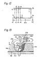
- a carrier 27b is combined with a downwardly extending arm 28b so that the arm 28b extends diagonally in the direction A as shown in Figs. 13 and 14.
- the arm 28b supports an agitator or agitators 25b at its lower end and, thus, the combination of the carrier 27b, arm 28b and the agitator(s) 25b imposes loads on the carriage beam 26b not only in a vertical direction by gravity but also in a pivoting direction by movement of a force due to the diagonal or canted arrangement of the arm 28b. Accordingly the combination above is movably supported on the surface of .
- Figs. 13 and 14 provides the further advantage that, if an inclination of the arm 28b is determined in connection with the penetrating pitch "p" of the agitator 25b so that the arm 28b itself may not interfere with the piled layer 19b during the transverse movement of the carrier 27b and the arm 28b, provision of the agitator 25b only at one side of the arm 28a in a way similar to that shown in Fig. 9 may present the possibility of following the locus represented in Fig. 12 thereby saving time compared to the locus of travel illustrated in Fig. 3.
- a plurality of composting floors may be provided as a multi-staged shelter.
- Such an example is illustrated in Figs. 15 and 16 as a two two-story shelter 16'.
- the components and elements similar in function to those in the 1st embodiment (Figs. 4 through 9) are given the same references as those corresponding thereto in the 1st embodiment except that the suffix "u" or a "l" is added to each thereof in the upper and lower floors, respectively. Therefore, the operation of this apparatus shown in Figs.
- the organic materials to be composted are delivered by a conveyor belt 44 and charged to an upper heaping zone 17u through an inlet port 23u by distributor 55 adapted to distribute the conveyed materials evenly along the witdh of the inlet port 23u.
- the materials plied in the upper heaping zone are turned over and displaced in a direction of Au by an agitator 25u during the zig-zag course thereof on an upper floor 18u.
- the materials thus displaced gradually fall through an outlet port 24u onto a lower floor 18t at its inlet port 23l from where the materials are further turned over or plowed up and gradually displaced toward an outlet port 24l by an agitator 25l during the zig-zag course thereof on a lower floor 18t and are discharged on a discharging conveyor 46.
- the shelter 16' has been explained as a two staged shelter, it is to be noted that the number of floors may be increased and it is not limited to two as illustrated.
- a still further or 5th embodiment of the present invention which is utilized for the composting materials piled in the open air or in the field.
- the organic materials are agitated and gradually displaced in a direction of A f from an inlet side 23f toward an outlet side 24f by an agitator 25f during its zig-zag movement such as the movement following a path b i ⁇ a i ⁇ a i+1 ⁇ a i+1 .
- the agitator 25f is preferably carried by a vehicle 47 which may be movable to trace the path above.
- each of the tips of the scraper blades 30f in the agitator 25f is shaped to have a "Y" shape as schematically illustrated in Fig. 18a so that it may scrape of a piled layer 19f efficiently irrespective of the rotational directions thereof.
- each of the scraper blades in the foregoing embodiment were given a curvature, respectively so that it may scrape the piled organic materials efficiently since it is unnecessary in those embodiments to reverse the rotational direction.
- the vehicle 47 may take the form of an automobile and, thus, it is preferable to rotate the agitator 25f by utilizing a power take out shaft extended from its engime in lieu of the motors in the previous embodiments.
- Fig. 18b there is shown an illustration similar to that shown in Fig. 18 so that the vehicle 47 is equipped with a front agitator 25 F and a rear agitator 25R.
- the rear agitator 25R throw the materials sent by the forward agitator 25F further and promotes breaking up or fractionizing of the organic materials.
- Figs. 8 and 9 are referenced again. While the movement of the carriage beam 26 in the direction of B is suspended, the agitator 25 is rotated in the direction of the arrow as indicated and traversed in the direction along the longitudinal direction of the beam 26.
- the height "H" of the piled layer 19 is preferably more than half the outer diameter "D" of the scraper blades 30 or it is further preferably more than the value of the outer diameter "Q" so that the organic materials are sent flying in the direction of arrows S in Fig. 8 to pass beyond the agitator 25 in the direction A assisted by blocking effect afforded by the edge of the piled layer deposited in such layer or thickness.
- the blades 30 penetrate the piled layer 19 of the materials, scrape off and send or throw the same flying and, therefore, the materials are divided, or broken up so as to remarkably increase the total surface area of the thrown materials which 4 re gently deposited on the floor 18 without packing down into a mass whereby resistance to air blown upwardly through the piled materials is kept low to facilitate and promote aerobic fermentation.
- the height H' of the piled layer 19 is less than half of the outer diameter "D" of the agitator scraper blades 30 such as shown in Fig. 8a, the rotation of the agitator 25 is preferably reversed as schematically shown in Fig.
- the scraped off materials are sent or thrown inthe direction S' passing the region where the agitator is traversing in a direction normal to the direction A and are gently piled with displacement in the same direction as A.
- the shape of blades such as illustrated in Fig. 18a may be employed if necessary. If the materials are piled high for some reason such as to increase the processing quantity of the materials per unit area, an additional agitator may be provided above the agitator disposed adjacent the floor. Such an arrangement is schematically illustrated in Fig.
- two agitators namely an upper agitator 25U and a lower agitator 25L are arranged to move in a direction vertical to the plane of the illustrated drawing while they are rotated in the direction of the arrows.
- the agitators 25U and 25L are also adapted to intermittently advance in the direction B towards an inlet port of the materials so that they are moved to trace a zig-zag path.
- the upper agitator 25U slightly forward relative to the lower agitator 25L with respect to the advancing direction B in order to allow each of the agitators to penetrate properly into the layer of materials.
- the agitator 25E comprises an endless linkage 50 having a plurality of scraper blades 30E, the linkage 50 being trained around a revolving means (not shown) so as to run in the direction of the arrows and send the organic materials scraped off flying in the same way as explained in the foregoing explanation.
- the agitator 25E is preferably leans backwards so that the upper portion is slightly behind the lower portion with respect to the advancing direction B as illustrated in the drawings.
- Fig. 23 the arrangement of the scraping blades 30 is illustrated so as to correspond to the agitator shown in Figs. 7, 8 and 9.
- the blades 30 are radially mounted on the shaft 29 in the same axial position whereas, in Fig. 23(II), the blades 30 are mounted on the shaft 29 in axially staggered relationship.
- the number and the axial position of the blades are not limited to those illustrated in the drawing and they may be modified as required. It is also preferably to construct the mounting of the blades so replacement thereof is easy.
- a carriage beam 26v is movably supported at its opposite ends by a pair of guide rails 14v.
- a carrier 27v is disposed on the carriage beam so as to move along the lengthwise direction of the beam 26v.
- Two vertical shafts 29v arranged to be driven by motors.32v are rotatably suspended from the carrier 27v and extend downwardly therefrom.
- Each shaft 29v is provided with a plurality of axial blades 30b radially mounted on the shaft 29b at the longitudinal edges thereof to construct an agitator 25v.
- Both the agitators 25v thus constructed are arranged to rotate in the same direction as indicated by arrows, in Fig. 26 during the movement of the carrier 27v on the carriage beam 26v or in the direction of 5v or 5v' traversing the direction of A or B so that the organic materials are agitated and displaced in the direction A. Since the rotational direction of the agitators 25v is to be reversed depending on the direction in which the carrier 27v is moving, the respective longitudinal edges of the blades 30b are preferably given "Y" shape similar to that shown in Fig. 18a.
- an agitator 25B in this embodiment comprises a rotatable core 60 of a disk shape supported at the lower portion of an arm 62 extending from a carrier (not shown but similar to those explained in the foregoing embodiments) and a plurality of buckets 61 mounted on the periphery of the core 60.
- a carrier not shown but similar to those explained in the foregoing embodiments
- Each of. the buckets 61 is provided with an edge 63 at the outer end thereof as well as side edges 64 thereby promoting the scraping effect thereof.
Abstract
Description
- The present invention relates generally to treatment of organic materials such as those discharged as municipal waste, organic sludge or excretions from stock farming and, more particularly, to a method and apparatus for converting such organic materials into compost.
- In the conventional process for composting organic materials, the general practice has been to store.or pile the organic materials to be composted for a certain period and to periodically turn them over at a proper time interval to promote aerobic fermentation, a proper amount of air being preferably fed to the stored materials from the bottom thereof during the storage which may be omitted if the materials are stored in the open air depending on the conditions such as the local or regional climate or environment. At any rate, operation for plowing or turning the piled materials over is indispensable in order to uniformly mix-the materials as well as to fractionalize the materials so as to substantially increase the total area of the surface of the materials exposed to air.
- On the other hand, it is necessary to displace the materials in a predetermined direction simultaneously with the plowing up or turning over operation if the composting operation is to be made continuous.
- In the appratus disclosed in the PCT application (PCT/JP78/00006) assigned to the Ebara Corporation, the aim was to increase the processing capacity of a multi-stage composting apparatus per unit area required for installation, and the apparatus has been admitted as satisfactory, for its intended purposes. However, due to its construction, the driving mechanism therefor is complex and the configuration has been limited to a circular base area. Sometimes, this construction may increase the operation cost and/or maintenance cost and may not be proper for use in a place where limitation on the field space is substantially neglegible.
- In the other conventional type composting apparatus also, an inherent disadvantage is that the necessary agitating and displacing device for performing continuous composting operation becomes large as the capacity of the apparatus is increased since an increase in the amount of materials to be received and stored in the apparatus necesitates an increase in capacity. Such increased capacity also causes an increase in the expense required for installation and maintenance of the apparatus. In view of the facts encountered in the composting apparatus of the prior art, there has been a great and constant need to provide a method and an apparatus which can handle a large quantity relatively economically.
- Accordingly, it is an object of the present invention to provide a method and an apparatus for composting large quantities of organic materials relatively economically.
- It is a further object of the present invention to increase the processing capacity of a method and apparatus for composting organic materials without need of substantially enlarging means for agitating and/or turning over the materials to be composted.
- It is still another object of the present invention to provide means and method for effectively fermenting the organic materials in conjunction with displacing and loosening the materials so as to prevent their packing down into a mass for increasing the total area of the materials exposed to air.
- According to the present invention, the objects above are satisfactorily accomplished.
- The organic materials to be composted are fed to a composting area or zone,the plan view of which is generally a rectangular shape,at an inlet of the composting zone and progressively displaced towards a discharge port of the composting zone by a revolving means adapted to travel in a zig-zag fashion within the composting zone so as to loosen or free the materials piled in the composting zone and incrementally displace the same from the inlet towards the outlet in a zig-zag course of travel. The rotational speed and the travelling speed of the revolving means are so selected so that the organic materials are loosened or freed and fed in a direction traversing the zig-zag travelling passage of the revolving means by a distance enough to pass beyond over the revolving means and laid on the composting zone again where the materials are deposited rather loosely without packing into a mass whereby aerobic fermentation is not prevented. The revolving means above, thus, effects simultaneously agitation and displacement of the materials to be composted and travels substantially over the entire surface of the composting zone. Due to such arrangement, the capacity of the composting apparatus is able to be increased without making the mechanism for displacing and agitating the materials substantially large in size. Such increase of the capacity is also materialized economically.
- The present invention will be made more clear from the detailed description of the invention referring to the accompanying drawings briefly summarized below.
-
- Fig. 1 is a plan view showing a basic locus which is traced by an agitator according to the present invention;
- Fig. 2 is a partial locus slightly different from that shown in Fig. 1;
- Fig. 3 is still another partial locus different from those in Figs. 1 and 2;
- Fig. 4 is a cross sectional view of a shelter in which composting operation is performed according to the present invention;
- Fig. 5 is another cross sectional view of the shelter shown in Fig. 4 taken in a direction perpendicular to the plane of Fig. 4;
- Fig. 6 is a schematic plan view of the embodiment shown in Figs. 4 and 5.
- Fig. 7 is a partial view of Fig. 4 showing the components of the agitator and its accompanying elements serving to have the agitator travel in zig-zag path;
- Fig. 8 is a side view of the portion shown in Fig. 7 and illustrates the operational mode of the agitator;
- Fig. 8a is an illustration similar to that shown in Fig. 8 but the agitator is oppositely rotated relative to the mode shown in Fig. 8;
- Fig. 10 is another embodiment of the present invention for effecting the zig-zag travel of the agitator;
- Fig. 11 is a perspective view of the embodiment shown in Fig. 10;
- Fig. 12 is a locus to be traced by the agitator shown in Figs. 10 and 12;
- Fig. 13 is an illustration of another agitator in motion together with its related elements;
- Fig. 14 is a side view of the embodiment shown in Fig. 13;
- Fig. 15 is a cross sectional view of a two-story shelter similar to that shown in Fig. 4;
- Fig. 16 is a cross sectional view of the shelter shown in Fig. 15 taken along the direction perpendicular to the plane of Fig. 15;
- Fig. 17 is a schematic plan view of a heaping zone suitable for use in the open air;
- Fig. 18 is a side view of an agitator carried on a vehicle and adapted for use in the heaping zone shown in Fig. 17;
- Fig. 18a is a simplified side view of the agitator used in the zone shown in Fig. 17;
- Fig. 18b is a modified version of the device shown in Fig. 18;
- Fig. 19 is a front view of the agitator shown in Figs. 18 or 18a together with its carrying vehicle in a side view;
- Fig. 20 is a further modified view of agitating means according to the present invention wherein an upper agitator and a lower agitator are employed;
- Fig 21 shows still another embodiment of the agitator using an endless linkage;
- Fig. 22 shows the agitator of Fig. 21 in motion thereof;
- Fig. 23 is an explanatory drawing illustrating the mounting of scraper blades on the shaft;
- Fig. 24 shows another embodiment of the present invention wherein the shaft of the agitator is mounted vertically;
- Fig. 25 is a cross sectional side view of the agitator shown in Fig. 24;
- Fig. 26 is a schematic cross sectional view taken perpendicular to the rotating axis or axes of the agitator shown in Fig. 25; and
- Fig. 27 is a still further modified form of an agitator.
- In Fig. 1, there is shown a schematic drawing of a plan view for illustrating a principle of the present invention. The composting process is carried out over an area or zone X of a generally rectangular shape. An agitating device 1 is arranged to be movable in the zone X while it is given a function to displace organic materials to be composted in a direction of an
arrow 2. Assuming that the organic materials are laid to cover the entire zone, the device 1 may start its movement from astarting point 4 adjacent adischarge end 3 and travels zig-zag in the directions indicated byarrows 5 and 5' traversing thedisplacement direction 2 andarrows 6 and 6' parallel to thedirection 2. When the agitation device 1 reaches a terminal point adjacent a supply or feedend 7, all the materials have been displaced in the direction ofarrow 2 by a distance of displacement effected by one passage of the agitating device 1 in thedirection 6 or 6'. Upon reaching theterminal point 8, the agitating device 1 will return along apath 11 in a direction of anarrow 12, which is separated from afermentation path 10 in the zone X by apartition wall 9 so as to be free of composting materials, and again reaches thestarting point 4. Thepartition wall 9 may be omitted provided that mechanism is associated with the device 1 for lifting agitating means upwardly above the height of the composting materials piled or deposited in the zone so as to clear the agitating means from the composting materials while the device is returning from thepoint 8 to thepoint 4. - There may be another locus or locuses of movement or travel of the device 1. Examples of such locuses are illustrated in Figs. 2 and 3. In Fig. 2, the locus is shown in case the travel of the device follows-in a direction of resultant vectors of the material displacement and those parallel and normal to the displacement. Such directions are shown as
arrows 13 and 13' in Fig. 2 in place of thearrows 6 and 6' in Fig. 1. In Fig. 1, the device travels on the same path as indicated by overlappedarrows 5 and 5' and advances toward the feed end by a distance equal to a pitch of zig-zag along the arrow 6' without travelling along thearrow 6 shown in Fig. 1. - Referring to Figs. 4, 5 and 6, there is shown an embodiment of the present invention in which composting operation is performed indoors. A fermenting
chamber 15 is enclosed within or covered by ashelter 16 and a compost material heaping or depositingzone 17 of a generally rectangular shape is provided on afloor 18 of the shelter and the materials before the composting operation, under the fermentation and after the fermentation are heaped in thezone 17 as a piledlayer 19. Thefloor 18 of thezone 17 is provided with a plurality ofperforations 20 through which air is injected upwardly from anair chamber 21 below thefloor 18 so as to promote the aerobic fermentation, the air chamber,21 being connected to an air source 22. One of the edges of the rectangular heapingzone 17 is adapted to receive organic materials to be composted and, for convenience, it is referred to as a material charging orinlet port 23 and the edge opposite theport 23 is a discharge oroutlet port 23 for discharging the fermented materials outwardly. Between theports inlet port 23 towards theoutlet port 24 by a revolving means illustrated as anagitator 25 which is adapted to travel a zig-zag course as illustrated in Figs. 1, 2 and 3. - In order to have the
agitator 25 travel a zig-zag course, acarriage 26 is provided to move back and forth over thefloor 18 and between theports carriage 26 extends transversely to the direction A and is movably supported at oppostie ends by a pair ofguide rails 14 mounted on the side walls or columns of theshelter 16. Thecarriage 26 is adapted to movably support acarrier 27 which is arranged to run on thecarriage 26 in the lengthwise direction thereof. Thecarrier 27 suspends theagitator 25 so that theagitator 25 may follow the zig-zag path when thecarriage 26 moves intermittently and incrementally in a direction B opposite to the direction A and continuously in the direction A, and the carrier moves transversly to the directions A and B on thecarriage 25 while the movement of the carriage is stopped. - The
agitator 25 is now described together with its accompanying elements and/or cooperating elements referring to Figs. 7, 8 and 9. Theagitator 25 is suspended by anarm 28 at a lower portion thereof which extends downwardly from thecarrier 27. Theagitator 25 comprises arotatable shaft 29 extending parallely to the moving direction of the carrier or the longitudinal direction of thecarriage 26, plural number ofscraper blades 30 radially mounted on theshaft 29 and amotor 31 for rotatably driving theshaft 29. The rotation of thescraper blades 30 scrapes up the piledlayer 19 of the organic materials and send the materials flying in a direction S shown in Fig. 8 so that the scraped materials are displaced in the direction of A opposite the direction of B. Therefore, the position of theagitator 25 is adjusted so that the bottom of the circumscribed circle of the tips of thescraper blades 30 is slightly above thefloor 18. Amotor 32 is provided for effecting the movement of thecarrier 27 on thecarriage 26 and amotor 33 is provided for effecting the intermittent or continuous movement of thecarriage 26. - Referring back to Figs. 4 and 6, a
return path 34 is provided adjacent the heapingzone 17 in order to facilitate the return movement of theagitator 25, thepath 34 being arranged to be substantially free from the organic materials or piledlayer 19. Thus, thepath 34 is substantially the same as thepath 11 in Fig. 1 and a partition wall (not shown) similar to 9 shown in Fig. 1 may also be provided between thepath 34 and thezone 17. Thepath 34 is naturally made wide enough to allow the movement of the agitator therealong without interference. - The operation of the embodiment illustrated in Figs. 4 through 9 is performed in a manner substantially the same as that illustrated in Fig. 3. Assuming that the piled
layer 19 of the organic materials covers the entire surface area of the heapingzone 17 some part thereof having been alreadly completely fermented and the other part thereof being under fermentation, theagitator 25 is arranged to commence its zig-zag course at a point "al" shown in Fig. 6 which corresponds to thepoint 4 in Fig. 3. With initiation of the revolution of theagitator 25 as schematically shown in Figs. 8 and 9, thecarrier 27 is also initiated to move on thecarriage 26 from the side of the point "al" toward a point "bl" opposite the point "a1" and thence back again to the point"ai while the movement of the carriage in the direction B is suspended during the back and forth movement of thecarrier 27 between the points "al" and "bl" corresponding to the first travel passage shown at the left end line in Fig. 3. (For convenience, the points "a1" and "bl" have been added to in Fig. 3 to where they correspond.) During the reciprocal movement of thecarrier 26 from the point "a1" to the point "bl" composted organic materials are displaced in the direction of A toward theoutlet port 24. When the movement of the carrier is between the points "al" and "bl" the displaced fermented materials are discharged outwardly through theoutlet port 24. Upon the return of thecarrier 27 with theagitator 25 to the point "a", thecarriage 26 is incrementably advanced in the direction B toward theinlet port 23 by a distance "p" and thence thecarrier 27 andagitator 25 are again moved reciprocately along the lengthwise direction of thecarriage 26 traversing the direction A or B and such travel of theagitator 25 is repeated until the agitator reaches the final point "an" after traveling the locus illustrated in Fig. 3 as the reciprocating paths al ↔b1, a2↔ b 2' --- an ↔ b with the additional movement of the paths 6'. The distance of the pitch "p" is determined to be equivalent to the dimention of therotating scraper blades 30 proper for penetrating into the piledlayer 19 for displacing the piled layer in the direction A. By the zig-zag course of the agitator from the starting point "a1" to the terminal point "an", the piled layer is displaced as a whole by a distance equivalent to the mean value "d" of the displacement of the materials scraped from theintermediate edge line 35 of the piled layer to be penetrated by theblades 30 to theintermediate edge line 36 of the layer of the materials thrown and re-piled on the floor by the rotation of the agitator as shown in Fig. 8. Theagitator 25 is returned to the starting point "a1" and the operation above is repeated. During the operation above, the organic materials are also charged through the inlet port in an appropriate amount to keep the operation continuous. In other words, the amount of the organic materials equivalent to that displaced by one transverse movement of the agitator must be charged through theinlet port 23 per one complete zig-zag course of theagitator 25 to keep the operation continuous. The actuations of therespective motors control unit 37 accompanied by position responsive means such as limit switches or timing means well known in the art. Although the operation above has been described to start from the starting point "al" since, after the commencement of the compositing operation, the entire surface of the heaping zone is generally covered by a layer of the materials to be worked or have been worked, the operation may be started at the intermediate position between the inlet andoutlet ports zone 17 is completely emptied. - In Figs. 10 and 11, another embodiment of the present invention is illustrated which is adapted to be used indoors as well as outdoors. The elements similar to those in the first embodiment of Figs. 4 through 9 with respect to the functions are given with the same reference as those in the first embodiment with a suffix "a" added to each thereof, respectively. A
carriage beam 28a equivalent to thecarriage 28 in the first embodiment is provided with a pair of supportinglegs 38 at the opposite end thereof to form a structure resembling agateway 39. Thegateway structure 39 is arranged to move in the direction A or B on a pair of floor or ground rails 39 extending transversely of the longitudinal direction of thecarriage beam 28a. In this embodiments, it is noted thatagitators 25a are disposed at opposite sides of anarm 28a so as to be driven by amotor 31a interposed therebetween. By such an arrangement, theagitators 25a may be operable in either of the moving directions in which acarrier 27a travels. Thus, a locus of the travel of theagitators 25a may be made similar to that shown in Fig. 1. More specifically, the travelling locus of theagitators 25a is schematically illustrated in Fig. 12. As shown in Figs. 10 and 11, a heapingzone 17a in this embodiment is provided with a pair ofside walls 40 and one of theside walls 40 and one of the supportinglegs 38 provide areturn track.path 34a therebetween. Due to the provision of theside wall 40, the locus of the travel illustrated in Fig. 12 is somewhat different from that shown in Fig. 1. In Fig. 12, a starting point α1 is shifted from a last point α1 in thereturn path 34a to clear the side wall. Also, for the same reason, a starting point αn' in thereturn path 34 is displaced from the last point a of the agitating travel locus. The agitating travel of theagitators 25a - commences at the point α1 and thence follows the zig-zag path as α1→β→1β→2→α2..... βn → αn and moves to the point αn' and repeats the operation explained. The operation following the locus illustrated in Fig. 12 saves the time compared to that required in the first embodiment whereagitator 25 is not driven or rotated while it travels backward after it has displaced the organic materials during its travel in the direction "a." to "b." in Figs. 3 and 6. - In Figs. 13 and 14, still another embodiment, i.e. a third one according to the present invention, is shown which is similar in function, to the second embodiment. In this embodiment, the elements and/or portions similar to those in the first embodiment are given the same references as in the first embodiment except that after each of the references the suffix "b" is added.
- In this embodiment, in contrast to the construction of the second embodiment (Figs. 10 and 11), a
carrier 27b is combined with a downwardly extendingarm 28b so that thearm 28b extends diagonally in the direction A as shown in Figs. 13 and 14. Thearm 28b supports an agitator oragitators 25b at its lower end and, thus, the combination of thecarrier 27b,arm 28b and the agitator(s) 25b imposes loads on thecarriage beam 26b not only in a vertical direction by gravity but also in a pivoting direction by movement of a force due to the diagonal or canted arrangement of thearm 28b. Accordingly the combination above is movably supported on the surface of . thecarriage beam 26b at threepoints carriage beam 26b thereby making it possible to lower the height of the under sidesurface of thebeam 26b by a distance "h" below a highest point of 44 where thrown materials may reach or to send the materials flying higher. If the height of thebeam 26b is lowered, the installation cost is also made economical and particularly, so if it is used indoors since the ceiling height of the shelter may be lowered. On the other hand, if the materials are sent flying higher, the displacing distance of the materials is increased which, depending on the conditions, promotes efficiency or increase the processing capacity. The construction shown in Figs. 13 and 14 provides the further advantage that, if an inclination of thearm 28b is determined in connection with the penetrating pitch "p" of the agitator 25b so that thearm 28b itself may not interfere with the piledlayer 19b during the transverse movement of thecarrier 27b and thearm 28b, provision of the agitator 25b only at one side of thearm 28a in a way similar to that shown in Fig. 9 may present the possibility of following the locus represented in Fig. 12 thereby saving time compared to the locus of travel illustrated in Fig. 3. - If it is desired to increase the capacity per unit area required for installation for some reason., for example, the area is limited, a plurality of composting floors may be provided as a multi-staged shelter. Such an example is illustrated in Figs. 15 and 16 as a two two-story shelter 16'. In this 4th embodiment of the present invention, the components and elements similar in function to those in the 1st embodiment (Figs. 4 through 9) are given the same references as those corresponding thereto in the 1st embodiment except that the suffix "u" or a "ℓ" is added to each thereof in the upper and lower floors, respectively. Therefore, the operation of this apparatus shown in Figs. 15 and 16 will be self-explanatory when the previous explanation of the 1st embodiment is referred to in connection with the brief explanation noted below on the portions peculiar to this 4th embodiments. The organic materials to be composted are delivered by a
conveyor belt 44 and charged to anupper heaping zone 17u through aninlet port 23u by distributor 55 adapted to distribute the conveyed materials evenly along the witdh of theinlet port 23u. The materials plied in the upper heaping zone are turned over and displaced in a direction of Au by an agitator 25u during the zig-zag course thereof on an upper floor 18u. The materials thus displaced gradually fall through an outlet port 24u onto a lower floor 18t at its inlet port 23ℓ from where the materials are further turned over or plowed up and gradually displaced toward an outlet port 24ℓ by an agitator 25ℓ during the zig-zag course thereof on a lower floor 18t and are discharged on a dischargingconveyor 46. While the shelter 16' has been explained as a two staged shelter, it is to be noted that the number of floors may be increased and it is not limited to two as illustrated. - In Figs. 17, 18, 18a, 18b and 19, there is illustrated a still further or 5th embodiment of the present invention which is utilized for the composting materials piled in the open air or in the field. In this embodiment, the organic materials are agitated and gradually displaced in a direction of Af from an inlet side 23f toward an outlet side 24f by an
agitator 25f during its zig-zag movement such as the movement following a path bi → ai → ai+1 → ai+1 ....... Theagitator 25f is preferably carried by avehicle 47 which may be movable to trace the path above. Since the materials are piled in the field, thevehicle 47 may freely turn its direction at a position outside of the composting zone as indicated by curved arrows. Therefore, the rotational direction of theagitator 25f is to be changed to the opposite direction at each turning of the vehicle. In compliance with such change of rotational direction, each of the tips of thescraper blades 30f in theagitator 25f is shaped to have a "Y" shape as schematically illustrated in Fig. 18a so that it may scrape of a piledlayer 19f efficiently irrespective of the rotational directions thereof. Incidentally, it is noted that each of the scraper blades in the foregoing embodiment were given a curvature, respectively so that it may scrape the piled organic materials efficiently since it is unnecessary in those embodiments to reverse the rotational direction. Thevehicle 47 may take the form of an automobile and, thus, it is preferable to rotate theagitator 25f by utilizing a power take out shaft extended from its engime in lieu of the motors in the previous embodiments. - In Fig. 18b, there is shown an illustration similar to that shown in Fig. 18 so that the
vehicle 47 is equipped with afront agitator 25F and arear agitator 25R. Therear agitator 25R throw the materials sent by theforward agitator 25F further and promotes breaking up or fractionizing of the organic materials. - Now the operation of the agitator is reviewed. For convenience, Figs. 8 and 9 are referenced again. While the movement of the
carriage beam 26 in the direction of B is suspended, theagitator 25 is rotated in the direction of the arrow as indicated and traversed in the direction along the longitudinal direction of thebeam 26. The height "H" of the piledlayer 19 is preferably more than half the outer diameter "D" of thescraper blades 30 or it is further preferably more than the value of the outer diameter "Q" so that the organic materials are sent flying in the direction of arrows S in Fig. 8 to pass beyond theagitator 25 in the direction A assisted by blocking effect afforded by the edge of the piled layer deposited in such layer or thickness. Theblades 30 penetrate the piledlayer 19 of the materials, scrape off and send or throw the same flying and, therefore, the materials are divided, or broken up so as to remarkably increase the total surface area of the thrown materials which 4re gently deposited on thefloor 18 without packing down into a mass whereby resistance to air blown upwardly through the piled materials is kept low to facilitate and promote aerobic fermentation. If the height H' of the piledlayer 19 is less than half of the outer diameter "D" of theagitator scraper blades 30 such as shown in Fig. 8a, the rotation of theagitator 25 is preferably reversed as schematically shown in Fig. 8a wherein the scraped off materials are sent or thrown inthe direction S' passing the region where the agitator is traversing in a direction normal to the direction A and are gently piled with displacement in the same direction as A. In order to provide the operational versatility of theagitator 25, the shape of blades such as illustrated in Fig. 18a may be employed if necessary. If the materials are piled high for some reason such as to increase the processing quantity of the materials per unit area, an additional agitator may be provided above the agitator disposed adjacent the floor. Such an arrangement is schematically illustrated in Fig. 20 wherein two agitators, namely anupper agitator 25U and alower agitator 25L are arranged to move in a direction vertical to the plane of the illustrated drawing while they are rotated in the direction of the arrows. Theagitators upper agitator 25U slightly forward relative to thelower agitator 25L with respect to the advancing direction B in order to allow each of the agitators to penetrate properly into the layer of materials. Also, it is preferable to arrange the circumferential speed of theupper agitator 25U greater than that of thelower agitator 25L so that the scraped materials are thrown farther by theupper agitator 25U than by thelower agitator 25L. - Another form of an
agitator 25E is illustrated in Figs. 21 and 22. Theagitator 25E comprises anendless linkage 50 having a plurality ofscraper blades 30E, thelinkage 50 being trained around a revolving means (not shown) so as to run in the direction of the arrows and send the organic materials scraped off flying in the same way as explained in the foregoing explanation. Theagitator 25E is preferably leans backwards so that the upper portion is slightly behind the lower portion with respect to the advancing direction B as illustrated in the drawings. - In Fig. 23, the arrangement of the
scraping blades 30 is illustrated so as to correspond to the agitator shown in Figs. 7, 8 and 9. In the Fig. 28(I), theblades 30 are radially mounted on theshaft 29 in the same axial position whereas, in Fig. 23(II), theblades 30 are mounted on theshaft 29 in axially staggered relationship. The number and the axial position of the blades are not limited to those illustrated in the drawing and they may be modified as required. It is also preferably to construct the mounting of the blades so replacement thereof is easy. - In the foregoing description and drawings all the agitators so far presented have been explained in terms of rotation about their horizontal axes. Now, a further embodiment of this invention wherein an agitator is rotated about a vertical axis is shown in Figs. 24, 25 and 26. In a manner similar to that shown in Fig. 9, a carriage beam 26v is movably supported at its opposite ends by a pair of guide rails 14v. A carrier 27v is disposed on the carriage beam so as to move along the lengthwise direction of the beam 26v. Two
vertical shafts 29v arranged to be driven by motors.32v are rotatably suspended from the carrier 27v and extend downwardly therefrom. Eachshaft 29v is provided with a plurality of axial blades 30b radially mounted on the shaft 29b at the longitudinal edges thereof to construct anagitator 25v. - Both the
agitators 25v thus constructed are arranged to rotate in the same direction as indicated by arrows, in Fig. 26 during the movement of the carrier 27v on the carriage beam 26v or in the direction of 5v or 5v' traversing the direction of A or B so that the organic materials are agitated and displaced in the direction A. Since the rotational direction of theagitators 25v is to be reversed depending on the direction in which the carrier 27v is moving, the respective longitudinal edges of the blades 30b are preferably given "Y" shape similar to that shown in Fig. 18a. - A still further modified form of the agitator is illustrated in Fig. 27. As shown in the drawing, an agitator 25B in this embodiment comprises a
rotatable core 60 of a disk shape supported at the lower portion of anarm 62 extending from a carrier (not shown but similar to those explained in the foregoing embodiments) and a plurality of buckets 61 mounted on the periphery of thecore 60. Each of. the buckets 61 is provided with anedge 63 at the outer end thereof as well as side edges 64 thereby promoting the scraping effect thereof. - The present invention has been explained in detail referring to the accompanying drawings, however, it is not limited to the embodiments illustrated in the accompanying drawings and the modification and change are, of course, available to those skilled in the art within the spirit and scope of the present invention which is defined in the claims appended hereto.
Claims (22)
Applications Claiming Priority (4)
| Application Number | Priority Date | Filing Date | Title |
|---|---|---|---|
| JP54065249A JPS5838395B2 (en) | 1979-05-26 | 1979-05-26 | Composting method and equipment |
| JP65249/79 | 1979-05-26 | ||
| JP87576/79 | 1979-07-11 | ||
| JP54087576A JPS5855118B2 (en) | 1979-07-11 | 1979-07-11 | composting equipment |
Publications (2)
| Publication Number | Publication Date |
|---|---|
| EP0021064A1 true EP0021064A1 (en) | 1981-01-07 |
| EP0021064B1 EP0021064B1 (en) | 1989-08-30 |
Family
ID=26406375
Family Applications (1)
| Application Number | Title | Priority Date | Filing Date |
|---|---|---|---|
| EP19800102914 Expired EP0021064B1 (en) | 1979-05-26 | 1980-05-24 | Method for composting |
Country Status (5)
| Country | Link |
|---|---|
| US (2) | US4410348A (en) |
| EP (1) | EP0021064B1 (en) |
| DE (1) | DE3020011A1 (en) |
| FR (1) | FR2457847A1 (en) |
| IT (1) | IT1197457B (en) |
Cited By (6)
| Publication number | Priority date | Publication date | Assignee | Title |
|---|---|---|---|---|
| US4410348A (en) * | 1979-05-26 | 1983-10-18 | Ebara Corporation | Method for composting |
| AT386821B (en) * | 1985-06-14 | 1988-10-25 | Vogel Werner Ing | Device for turning over refuse in a composting area |
| WO1993016017A1 (en) * | 1992-02-12 | 1993-08-19 | Ntp-Yhtymä Oy | Mechanical composting |
| WO1995015933A1 (en) * | 1993-12-06 | 1995-06-15 | Bioplan A/S | A composting plant for organic waste and method for composting such waste |
| EP0768286A1 (en) * | 1995-10-11 | 1997-04-16 | Ebara Corporation | Horizontal paddle type fermentation system and method of operating the same |
| WO2014095390A1 (en) * | 2012-12-21 | 2014-06-26 | Tsp Gmbh | Device for turning, mixing and transporting partially dried material to be dried or dried material |
Families Citing this family (17)
| Publication number | Priority date | Publication date | Assignee | Title |
|---|---|---|---|---|
| CN1044701C (en) * | 1985-04-05 | 1999-08-18 | 株式会社荏原制作所 | Apparatus for stirring fermenter |
| DE3605258A1 (en) * | 1986-02-19 | 1987-08-20 | Georg Dipl Ing Neumann | METHOD AND DEVICE FOR COMPOSTING SOLID AND LIQUID ORGANIC WASTE |
| FR2597860B1 (en) * | 1986-04-25 | 1990-09-28 | Omnium Traitement Valorisa | FERMENTATION ASSEMBLY WITH BACKHOE WHEEL |
| US5149196A (en) * | 1987-10-02 | 1992-09-22 | International Process Systems | Compost handling machine |
| US4828399A (en) * | 1987-10-02 | 1989-05-09 | International Process Systems | Compost handling machine |
| DE3912474A1 (en) * | 1988-04-16 | 1989-11-02 | Stratmann Staedtereinigung Gmb | Process for the preparation of compost |
| HU213559B (en) * | 1989-03-28 | 1997-08-28 | Buehler Ag | Composting plant and process for the production of compost materials of different degrees of ripeness |
| DE3934379C1 (en) * | 1989-10-14 | 1990-12-13 | Salzgitter Maschinenbau Gmbh, 3320 Salzgitter, De | |
| US5204263A (en) * | 1991-09-27 | 1993-04-20 | Bedminster Bioconversion Corporation | Channel cover |
| US5348103A (en) * | 1992-08-19 | 1994-09-20 | Lh Resource Management Inc. | Composting machine |
| US5459071A (en) * | 1994-05-02 | 1995-10-17 | Bedminster Biconversion Corporation | Compost curing system |
| ES2205346T3 (en) * | 1997-08-25 | 2004-05-01 | Tilo Dr. Conrad | VOLTEADOR DEVICE FOR MUDS AND DISPERSIONS AND SOLAR DRYER WITH VOLTEADOR DEVICE. |
| FR2811981A1 (en) * | 2000-07-24 | 2002-01-25 | Jean Claude Chenu | Continuous composting comprises using tunnels filled with organic waste, fermenter with spiral mixer moving along guide rails in tunnels and gas collection devices in tunnels |
| US6766592B1 (en) | 2001-12-10 | 2004-07-27 | Willard Clark | Chicken manure processing apparatus |
| US6560895B1 (en) | 2001-12-10 | 2003-05-13 | Willard Clark | Chicken manure processing apparatus |
| FR2857086B1 (en) * | 2003-07-02 | 2006-09-15 | Otv Sa | DEVICE FOR TREATING A WET WASTE |
| US20100162589A1 (en) * | 2007-07-19 | 2010-07-01 | Gedalyahu Manor | Method for processing and drying waste in a continuous process |
Citations (5)
| Publication number | Priority date | Publication date | Assignee | Title |
|---|---|---|---|---|
| GB521894A (en) * | 1938-11-24 | 1940-06-04 | James Alger Coombs | Improvements in or relating to a process for the manufacture of fertilizers |
| FR1302793A (en) * | 1961-10-06 | 1962-08-31 | Compost Engineers Ltd | Improvements in the treatment of pulverized organic materials |
| CH491796A (en) * | 1966-08-25 | 1970-06-15 | Buehler Ag Geb | Method and device for shifting compost heaps - KE 6z - |
| CH496600A (en) * | 1969-04-29 | 1970-09-30 | Gewerk Eisenhuette Westfalia | Device for moving garbage stored in rows for composting |
| US3881707A (en) * | 1972-04-05 | 1975-05-06 | Louis R Toto | Scoop means and arrangements thereof for vehicular composting machine |
Family Cites Families (21)
| Publication number | Priority date | Publication date | Assignee | Title |
|---|---|---|---|---|
| GB496637A (en) * | 1937-05-25 | 1938-11-25 | James Alger Coombs | Improvements in or relating to mechanical labourers |
| GB543865A (en) * | 1940-09-14 | 1942-03-17 | James Alger Coombs | Improvements in or relating to a plant for the treatment of water supplies for domestic use, sewage and the like, and the manufacture of fertilisers |
| US2798800A (en) * | 1954-03-01 | 1957-07-09 | Modoc Peat Moss Company | Process of compositing municipal refuse in windrows |
| US3364007A (en) * | 1962-11-30 | 1968-01-16 | Garbage Service Company Inc | Method of composting waste materials |
| US3357812A (en) * | 1964-10-20 | 1967-12-12 | John R Snell | Method and apparatus for the aerobic composting of organic waste material |
| US3323896A (en) * | 1965-10-18 | 1967-06-06 | New Life Foundation | Composting method |
| AU410720B2 (en) * | 1965-12-13 | 1971-03-02 | Douglas Griffin Gordon | Composting machine |
| US3438740A (en) * | 1966-02-01 | 1969-04-15 | New Life Foundation | Composting conveyor |
| DE1917268A1 (en) * | 1969-04-03 | 1970-10-15 | Metallgesellschaft Ag | Community rubbish disposal |
| US3664645A (en) * | 1970-03-30 | 1972-05-23 | Cobey H T | Compost and refuse shredding and shifting apparatus |
| DE2302882B2 (en) * | 1973-01-20 | 1980-04-17 | Maschinenfabrik Fahr Ag Gottmadingen, 7702 Gottmadingen | Composting plant |
| DE2302805B2 (en) * | 1973-01-20 | 1981-04-16 | Maschinenfabrik Fahr Ag Gottmadingen, 7702 Gottmadingen | Carousel system for composting garbage |
| ZA743720B (en) * | 1973-07-11 | 1975-08-27 | Ohio Feed Lot | Process for aerobic thermophilic decomposition of organic waste |
| DE2364656C2 (en) * | 1973-12-24 | 1981-10-08 | Maschinenfabrik Fahr Ag Gottmadingen, 7702 Gottmadingen | Transfer device for compost heaps |
| DE2415068A1 (en) * | 1974-03-28 | 1975-11-20 | Renova Abfallhygiene Gmbh & Co | Composting of refuse and other waste material - by aerobic rotting of the milled and sieved material |
| DE2520640A1 (en) * | 1975-05-09 | 1976-11-18 | Renova Abfallhygiene Gmbh & Co | Aerobic composting of household rubbish, sewage sludge, etc. - in which stack is force ventilated in both directions intermittently |
| JPS5221174A (en) * | 1975-08-13 | 1977-02-17 | Niigata Engineering Co Ltd | Apparatus for producing compost |
| IT1055674B (en) * | 1975-11-12 | 1982-01-11 | Fiat Spa | PLANT AND MACHINE FOR OUMULT HANDLING PARTICULARLY FOR FERMENTATION AND PROCESSING WASTE |
| JPS6029775B2 (en) * | 1976-05-28 | 1985-07-12 | 旭化成株式会社 | Fabric products and manufacturing methods thereof |
| JPS5450874A (en) * | 1977-09-30 | 1979-04-21 | Hitachi Ltd | Method of connecting parts on substrate and device therefor |
| IT1197457B (en) * | 1979-05-26 | 1988-11-30 | Ebara Corp | PROCESS AND EQUIPMENT FOR THE PRODUCTION OF FERTILIZERS |
-
1980
- 1980-05-23 IT IT2230280A patent/IT1197457B/en active
- 1980-05-24 DE DE3020011A patent/DE3020011A1/en active Granted
- 1980-05-24 EP EP19800102914 patent/EP0021064B1/en not_active Expired
- 1980-05-27 FR FR8011688A patent/FR2457847A1/en active Granted
-
1982
- 1982-01-28 US US06/344,074 patent/US4410348A/en not_active Expired - Lifetime
- 1982-09-24 US US06/423,216 patent/US4495290A/en not_active Expired - Lifetime
Patent Citations (5)
| Publication number | Priority date | Publication date | Assignee | Title |
|---|---|---|---|---|
| GB521894A (en) * | 1938-11-24 | 1940-06-04 | James Alger Coombs | Improvements in or relating to a process for the manufacture of fertilizers |
| FR1302793A (en) * | 1961-10-06 | 1962-08-31 | Compost Engineers Ltd | Improvements in the treatment of pulverized organic materials |
| CH491796A (en) * | 1966-08-25 | 1970-06-15 | Buehler Ag Geb | Method and device for shifting compost heaps - KE 6z - |
| CH496600A (en) * | 1969-04-29 | 1970-09-30 | Gewerk Eisenhuette Westfalia | Device for moving garbage stored in rows for composting |
| US3881707A (en) * | 1972-04-05 | 1975-05-06 | Louis R Toto | Scoop means and arrangements thereof for vehicular composting machine |
Cited By (6)
| Publication number | Priority date | Publication date | Assignee | Title |
|---|---|---|---|---|
| US4410348A (en) * | 1979-05-26 | 1983-10-18 | Ebara Corporation | Method for composting |
| AT386821B (en) * | 1985-06-14 | 1988-10-25 | Vogel Werner Ing | Device for turning over refuse in a composting area |
| WO1993016017A1 (en) * | 1992-02-12 | 1993-08-19 | Ntp-Yhtymä Oy | Mechanical composting |
| WO1995015933A1 (en) * | 1993-12-06 | 1995-06-15 | Bioplan A/S | A composting plant for organic waste and method for composting such waste |
| EP0768286A1 (en) * | 1995-10-11 | 1997-04-16 | Ebara Corporation | Horizontal paddle type fermentation system and method of operating the same |
| WO2014095390A1 (en) * | 2012-12-21 | 2014-06-26 | Tsp Gmbh | Device for turning, mixing and transporting partially dried material to be dried or dried material |
Also Published As
| Publication number | Publication date |
|---|---|
| DE3020011A1 (en) | 1981-04-02 |
| IT8022302A0 (en) | 1980-05-23 |
| DE3020011C2 (en) | 1992-01-02 |
| IT1197457B (en) | 1988-11-30 |
| EP0021064B1 (en) | 1989-08-30 |
| US4495290A (en) | 1985-01-22 |
| FR2457847A1 (en) | 1980-12-26 |
| US4410348A (en) | 1983-10-18 |
| FR2457847B1 (en) | 1984-03-02 |
Similar Documents
| Publication | Publication Date | Title |
|---|---|---|
| EP0021064A1 (en) | Method for composting | |
| US3294491A (en) | Composting apparatus | |
| EP0008601B1 (en) | Compost making apparatus | |
| US4776960A (en) | Plant for aerobic biological transformation of organic waste | |
| EP0768286B1 (en) | Horizontal paddle type fermentation system and method of operating the same | |
| EP0066220B1 (en) | Composting apparatus | |
| CN1443148A (en) | Method and apparatus for moving and stirring compost | |
| EP0145874B1 (en) | Composting plant for refuse and sludge | |
| JPS5838395B2 (en) | Composting method and equipment | |
| US3276845A (en) | Apparatus for composting waste materials | |
| KR200182812Y1 (en) | Fermenting apparatus of compost | |
| JPS6137238B2 (en) | ||
| JPH0480730B2 (en) | ||
| JPS6341874B2 (en) | ||
| JPS5855118B2 (en) | composting equipment | |
| JP2000063190A (en) | Fermentatively composting system | |
| JP3193968B2 (en) | Waste decomposition treatment apparatus and waste decomposition treatment method | |
| JP2004161568A (en) | Compost manufacturing apparatus | |
| KR800000024B1 (en) | Apparatus for producing composts | |
| JPH07214045A (en) | Urine circulating device of continuous excrete fermenting and drying treatment device | |
| JP2002274990A (en) | Compost making system and method for the same | |
| JPS5829140Y2 (en) | Livestock manure composting equipment | |
| JPH0733568A (en) | Agitating transfer apparatus | |
| JPS6137237B2 (en) | ||
| JPS6146437B2 (en) |
Legal Events
| Date | Code | Title | Description |
|---|---|---|---|
| PUAI | Public reference made under article 153(3) epc to a published international application that has entered the european phase |
Free format text: ORIGINAL CODE: 0009012 |
|
| AK | Designated contracting states |
Designated state(s): NL |
|
| 17P | Request for examination filed |
Effective date: 19810227 |
|
| GRAA | (expected) grant |
Free format text: ORIGINAL CODE: 0009210 |
|
| AK | Designated contracting states |
Kind code of ref document: B1 Designated state(s): NL |
|
| PLBE | No opposition filed within time limit |
Free format text: ORIGINAL CODE: 0009261 |
|
| STAA | Information on the status of an ep patent application or granted ep patent |
Free format text: STATUS: NO OPPOSITION FILED WITHIN TIME LIMIT |
|
| 26N | No opposition filed | ||
| PGFP | Annual fee paid to national office [announced via postgrant information from national office to epo] |
Ref country code: NL Payment date: 19980531 Year of fee payment: 19 |
|
| PG25 | Lapsed in a contracting state [announced via postgrant information from national office to epo] |
Ref country code: NL Free format text: LAPSE BECAUSE OF NON-PAYMENT OF DUE FEES Effective date: 19991201 |
|
| NLV4 | Nl: lapsed or anulled due to non-payment of the annual fee |
Effective date: 19991201 |
|
| APAH | Appeal reference modified |
Free format text: ORIGINAL CODE: EPIDOSCREFNO |