EP0767016B1 - Procédé et dispositif pour mesurer des rayons de pièces cintrées - Google Patents
Procédé et dispositif pour mesurer des rayons de pièces cintrées Download PDFInfo
- Publication number
- EP0767016B1 EP0767016B1 EP19960115724 EP96115724A EP0767016B1 EP 0767016 B1 EP0767016 B1 EP 0767016B1 EP 19960115724 EP19960115724 EP 19960115724 EP 96115724 A EP96115724 A EP 96115724A EP 0767016 B1 EP0767016 B1 EP 0767016B1
- Authority
- EP
- European Patent Office
- Prior art keywords
- fact
- roller
- bending
- centre
- cylinder
- Prior art date
- Legal status (The legal status is an assumption and is not a legal conclusion. Google has not performed a legal analysis and makes no representation as to the accuracy of the status listed.)
- Expired - Lifetime
Links
Images

Classifications
-
- B—PERFORMING OPERATIONS; TRANSPORTING
- B21—MECHANICAL METAL-WORKING WITHOUT ESSENTIALLY REMOVING MATERIAL; PUNCHING METAL
- B21D—WORKING OR PROCESSING OF SHEET METAL OR METAL TUBES, RODS OR PROFILES WITHOUT ESSENTIALLY REMOVING MATERIAL; PUNCHING METAL
- B21D7/00—Bending rods, profiles, or tubes
- B21D7/14—Bending rods, profiles, or tubes combined with measuring of bends or lengths
-
- B—PERFORMING OPERATIONS; TRANSPORTING
- B21—MECHANICAL METAL-WORKING WITHOUT ESSENTIALLY REMOVING MATERIAL; PUNCHING METAL
- B21D—WORKING OR PROCESSING OF SHEET METAL OR METAL TUBES, RODS OR PROFILES WITHOUT ESSENTIALLY REMOVING MATERIAL; PUNCHING METAL
- B21D7/00—Bending rods, profiles, or tubes
- B21D7/08—Bending rods, profiles, or tubes by passing between rollers or through a curved die
Definitions
- the invention relates to a method for determining Radii in - bending parts defining - two cylinder surfaces, an inner cylindrical surface having a center of curvature facing as well as a second - outer - cylinder surface this is turned away.
- the invention also covers a device particularly suitable for this method.
- a portable device for bending pipes is an example can be found in DE-PS 32 09 539.
- a measurement the curvature can be done, for example, by hand using a Three-point measuring device.
- Radii can be curved Objects, for example with the so-called three-point measuring method, using strain gauges and measuring methods, where - touching or non-contact - several Detects points on a contour and uses this to calculate the radius becomes (see for example GB-A-2087561), however, many of these methods are either relatively imprecise or tied to boundary conditions that in can hardly be followed in practice.
- the inventor was aware of this state of the art set the goal, a measuring method and a device to develop with the help of the radius of the arc of bent parts by means of fewer and easy to grasp geometrical Sizes can be determined.
- the length of the radius of the inner cylinder surface closer to the center of curvature is determined as a quotient from the radial distance between the two cylinder surfaces as a dividend and a divisor which is the difference of the quotient of the arc length of the outer cylinder surface by the arc length of the inner cylinder surface minus the subtrahend 1.
- the three geometric sizes are determined using two - preferably identical - friction wheel encoder units, which are arranged opposite each other; each this unit is mounted on a separate carriage, and both sledges can be independent of each other be moved on a common linear guide.
- Each one of these Sled is an energy store, especially one Compression spring, assigned. Thanks to this requirement is a continuous Ensure that the friction wheels rest on the curved object; this is between the two described Friction wheels. That continuous plant of Friction wheels are supported by the proviso that the Compression spring of the outer slide with a higher force is equipped as the compression spring of the inner slide.
- the distance between the Cylinder surfaces with a displacement transducer known per se in a bending machine or outside of it - for example with a handheld meter - be measured on the bent part.
- the distance between the carriage can also be detected by a displacement sensor; this Distance corresponds to the width of the curved object.
- Rod 10 corresponds to the distance from its outer Side surface 12 to that not recognizable in the drawing Center of curvature of the sum of the rod width b and the inner bending radius Ri, i.e. the distance of the inner one Side surface 14 to that center of curvature.
- Each of the two side surfaces 12, 14 determine one of two to each other equidistant cylinder surface sections.
- the acquisition of the three geometric sizes is in the Made that the arc lengths La, Li by means of a outer and an inner friction wheel encoder 16 and 18 as well the distance b between the two cylinder or side surfaces 12.14 by a potentiometric displacement sensor be determined.
- the friction wheel rotary encoders 16, 18 are located on two slides 20, 20 i , which can move independently of one another on a linear guide 22 oriented radially to the arc segment.
- a continuous application of the friction wheels 17 of that friction wheel encoder units 16,18 at those side faces 12,14 is achieved i with two compression springs 24,24, the i are supported in each case at one end to the carriage 24 and 24 respectively. Since the outer compression spring 24 exerts a higher force on its slide 20 than the inner compression spring 24 i on the inner slide 20 i , a continuous application of guide rollers 26 on the curved rod 10 is achieved at the same time.
- the guide rollers 26 are two at the ends - each offered by part of a guide beam 28 - side arms of a T-shaped guide tree 30 in plan view fixed, the central bar forms that linear guide 22. Their necessary radial alignment is compared to that of you reach the guide bar 28 protruding at right angles, from the free ends of each one - for linear guidance parallel - bearing arm 32 protrudes for those guide rollers 26.
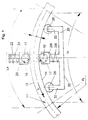
- FIG. 2 shows the measuring device integrated to capture the two arc lengths of the bent part in a typical three-roll bending machine with bending rolls 35 to 37.
- the main difference to the execution 1 is that the measuring unit in FIG. 2 has no guide bar 22 with guide rollers 26, the other version for the continuous radial Alignment of the measuring unit on the bent part ensures. Instead, the common linear guide 22 on the machine body after previous alignment either in steps adjustable - or not adjustable - attached.
- the linear guide 22 can either be behind the bending roller 37 or even just before the bending roller 37 in the feed direction x seen, i.e. in the space between middle role 35 and bending roller 37 are positioned.
Landscapes
- Engineering & Computer Science (AREA)
- Mechanical Engineering (AREA)
- A Measuring Device Byusing Mechanical Method (AREA)
- Length Measuring Devices With Unspecified Measuring Means (AREA)
Claims (17)
- Procédé pour établir les rayons des pièces pliées (10) déterminées par deux surfaces cylindriques, où une surface de cylindre intérieure (14) est tournée vers un centre de courbure et une deuxième surface de cylindre est détournée de celui-ci,
caractérisé par le fait
que la longueur du rayon (Ri) de la surface cylindrique (14) étant plus proche au centre de courbure est déterminé comme le quotient de la distance radiale (b) des deux surfaces cylindriques (14, 12) comme dividende et un diviseur du quotient de la longueur de l'arc (La) de la surface extérieur et la longueur (Li) de la surface intérieur moins le subrahent 1. - Procédé selon le droit 1, caractérisé par le fait que la distance radiale (b) entre les surfaces cylindriques (12, 14) est mesurée après avoir déterminé les longueurs d'arc (Li, La).
- Procédé selon le droit 1 ou 2, caractérisé par le fait que, pendant la flexion, les longueurs d'arc (Li, La) sont mesurées en plusieurs phases de déformation et indépendant de l'orientation radiale.
- Procédé selon un des droits 1 à 3, caractérisé par le fait qu'au moins une des longueurs (Li, La) est mesurée sans contact.
- Dispositif pour effectuer un mesurage selon un des droits 1 à 4, caractérisé par le fait que deux unités de roue de friction encodeur (16, 18) déterminent un diamètre intérieur pour la pièce pliée (10), ou chacune des unités de roue de friction encodeur est montée sur un glissoire (20, 20i) et toutes les deux peuvent être mues sur une glissière linéaire (22) commune. La glissière linéaire (22) peut être alignée radialement par rapport à la pièce pliée courbée se trouvant dans le diamètre intérieur.
- Dispositif selon le droit 5, caractérisé par le fait que chaque glissoire (20, 20i), à son côté détourné de la pièce pliée (10), s'appuie contre un accumulateur d'énergie (24, 24i).
- Dispositif selon le droit 5 ou 6, caractérisé par le fait que la glissière linéaire (22) et part d'un arbre de guidage (30) contenant un bras conducteur traversant (28). A chaque extrémité libre du bras, une roulette de guidage (26) est montée pour la pièce pliée.
- Dispositif selon un des droits 5 à 7, caractérisé par le fait que le bras conducteur (28) est courbé en soi-même.
- Dispositif selon le droit 7, caractérisé par le fait que le bras conducteur (28) est en position perpendiculaire par rapport à la glissière linéaire (22).
- Dispositif selon un des droits 7 à 9, caractérisé par le fait qu'à tous extrémités libres du bras de conducteur (28) un chaise (32) pour une roulette de guidage descend.
- Dispositif selon le droit 10, caractérisé par le fait que le chaise (28) s'étire environ en parallèle par rapport à la glissière linéaire (22).
- Dispositif selon un des droits 6 à 11, caractérisé par le fait que le l'accumulateur d'énergie du guide(20) se trouvent radial extérieur a une force plus grande que l'accumulateur d'énergie (24) du guide (20i) se trouvant radial intérieur.
- Dispositif selon un des droits 5 à 12, caractérisé par un capteur de distance pour déterminer la distance (b) entre les guides (20, 20i) respectivement les surfaces des cylindres (12, 14) de la part pliée.
- Dispositif selon un des droits 5 à 13, caractérisé par le fait que les guides (20, 20i) procèdent, en direction de transport (x) à tous les deux côtés de la voie de mouvement pour la pièce pliée, au moins la circonférence d'une roulette (35, 36, 37)
- Dispositif selon un des droits 5 à 14, caractérisé par le fait que le la glissière linéaire commune (22) est montée avec les guides (20, 20i) dans l'espace entre une roulette centrale (35) et une roulette de courbure (37), préférablement en direction d'avancement (x) un peu devant la roulette de courbure.
- Dispositif selon le droit 14 ou 15, caractérisé par le fait qu'au côté intérieur de courbure de la pièce pliée (10) une roulette centrale (35) est prévue faisant face au côté extérieure de courbure à une roulette de guidage (36) et à une roulette de courbure (37) près du guide.
- Dispositif selon un des droits 14 à 16, caractérisé par le fait que la roulette de guidage (36) et la roulette de courbure (37) se trouvent aux côtés différents d'une axe central diamétral allant à travers le centre (M) de la roulette centrale (35).
Applications Claiming Priority (2)
| Application Number | Priority Date | Filing Date | Title |
|---|---|---|---|
| DE19536938 | 1995-10-04 | ||
| DE19536938 | 1995-10-04 |
Publications (3)
| Publication Number | Publication Date |
|---|---|
| EP0767016A2 EP0767016A2 (fr) | 1997-04-09 |
| EP0767016A3 EP0767016A3 (fr) | 1997-12-03 |
| EP0767016B1 true EP0767016B1 (fr) | 1999-06-02 |
Family
ID=7773990
Family Applications (1)
| Application Number | Title | Priority Date | Filing Date |
|---|---|---|---|
| EP19960115724 Expired - Lifetime EP0767016B1 (fr) | 1995-10-04 | 1996-10-01 | Procédé et dispositif pour mesurer des rayons de pièces cintrées |
Country Status (2)
| Country | Link |
|---|---|
| EP (1) | EP0767016B1 (fr) |
| DE (1) | DE19602504A1 (fr) |
Families Citing this family (6)
| Publication number | Priority date | Publication date | Assignee | Title |
|---|---|---|---|---|
| IT1394105B1 (it) * | 2009-05-06 | 2012-05-25 | Cml Int Spa | Macchina per curvare in modo continuo un pezzo allungato secondo raggi predeterminati |
| IT1400500B1 (it) * | 2010-06-22 | 2013-06-11 | Crippa Spa | Procedimento per la curvatura di tubi, fili o nastri di metallo a serpentina o a molla e macchinaper curva tubi, fili o nastri di metallo per la fabbricazione di una serpentina o una molla presentante un andamento ad elica comprendente una pluralità di spire |
| ITTO20130936A1 (it) | 2013-11-19 | 2015-05-20 | Cte Sistemi Srl | Gruppo di misura per misurare il raggio di curvatura e l'avanzamento in una macchina curvatrice, in particolare in una macchina curvatrice per la curvatura di conduttori per bobine superconduttive |
| DE102016013144A1 (de) * | 2016-10-31 | 2018-05-03 | Technische Universität Dortmund | Vorrichtung zur taktilen Erfassung und Analyse der Geometrie von gebogenen Profilen oder Rohren |
| DE102020127164B3 (de) * | 2020-10-15 | 2021-07-15 | Jenoptik Industrial Metrology Germany Gmbh | Radialkraft-Vorrichtung für ein Konturmessgerät und Messsystem |
| CN113884958B (zh) * | 2021-09-27 | 2023-07-25 | 中国科学院合肥物质科学研究院 | 一种测量超导带材临界侧弯半径的装置及方法 |
Family Cites Families (5)
| Publication number | Priority date | Publication date | Assignee | Title |
|---|---|---|---|---|
| CH572200A5 (fr) * | 1973-09-18 | 1976-01-30 | Haeusler Christian Ag | |
| DE3041212C2 (de) * | 1980-11-03 | 1982-08-26 | August Wilhelm 5901 Wilnsdorf Schäfer | Vorrichtung zum Biegen, insbesondere Runden von Blechen oder Profilen |
| GB2087561A (en) * | 1980-11-11 | 1982-05-26 | Smt Pullmax | Apparatus for measuring the curvature of a single-curved surface |
| US4532787A (en) * | 1981-03-16 | 1985-08-06 | C.M.L. Costruzioni Meccaniche Liri S.R.L. | Portable electromechanically-controlled pipe-bending apparatus |
| DE4225878C2 (de) * | 1992-08-05 | 1996-02-29 | Bayer Isolierglasfab Kg | Verfahren und Vorrichtung zum Biegen eines Bogens an einem hohlen Abstandhalterprofil |
-
1996
- 1996-01-25 DE DE19602504A patent/DE19602504A1/de not_active Withdrawn
- 1996-10-01 EP EP19960115724 patent/EP0767016B1/fr not_active Expired - Lifetime
Also Published As
| Publication number | Publication date |
|---|---|
| EP0767016A3 (fr) | 1997-12-03 |
| DE19602504A1 (de) | 1997-04-10 |
| EP0767016A2 (fr) | 1997-04-09 |
Similar Documents
| Publication | Publication Date | Title |
|---|---|---|
| EP0916425B1 (fr) | Dispositif de dressage d'un laminé | |
| EP0494430B1 (fr) | Procédé pour mesurer le diamètre des cylindes, en particulier des tambours | |
| EP2093537A1 (fr) | Système et procédé pour déterminer l'alignement de deux pièces de machine rotatives, l'alignement de deux cylindres creux, ou pour éprouver la rectitude d'u component | |
| DE2704122C2 (de) | Andrückvorrichtung für eine Drahtwickelmaschine | |
| EP0767016B1 (fr) | Procédé et dispositif pour mesurer des rayons de pièces cintrées | |
| DE7010870U (de) | Vorrichtung zum schleifen der oberflaeche von gedrechselten gegenstaenden. | |
| DE3816130C2 (fr) | ||
| DE19502918B4 (de) | Vorrichtung zur kontinuierlichen Herstellung längsnahtgeschweißter dünnwandiger schraubenlinien- oder ringförmig gewellter Metallrohre | |
| EP0348340B1 (fr) | Procédé et dispositif pour la détection du cours de l'axe d'un corps allongé cylindrique | |
| DE3211489A1 (de) | Verfahren und vorrichtung zur korrektur von sollform-abweichungen platisch verformbarer gegenstaende | |
| AT506313A4 (de) | Biegegesenk für eine biegepresse, insbesondere abkantpresse | |
| EP3517923B1 (fr) | Dispositif d'avancement pour un système d'inspection | |
| DE69829295T2 (de) | Verfahren und vorrichtung zum messen einer aussenoberfläche | |
| EP0033310A1 (fr) | Dispositif de mesure prévu à un chemin de roulement formé de rouleaux montés à rotation et méthode pour l'interprétation de la valeur mesurée | |
| WO2001024953A1 (fr) | Dresseuse servant a dresser des corps allonges | |
| WO1989009104A1 (fr) | Procede et dispositif de cintrage de materiaux, de preference sous forme de barres | |
| DE3322777A1 (de) | Verfahren zum richtenden umformen, insbesondere biegerichten und/oder torsionsrichten, von werkstuecken | |
| DE3025320A1 (de) | Verfahren und vorrichtung zum zufuehren von stangenmaterial um vorbestimmte laengen | |
| EP1221584A1 (fr) | Procédé et dispositif d'alignement d'un véhicule relatif à sa direction de course | |
| DE2362805B2 (de) | Meßwertgeberanordnung | |
| EP0384477A2 (fr) | Procédé et machine de pliage de tubes | |
| WO2022017969A1 (fr) | Dispositif de transport de fil métallique et procédé | |
| DE102019205798A1 (de) | Nachführsteuerung für eine Induktionshärteanlage | |
| DE3815304A1 (de) | Verfahren und vorrichtung zum biegen bzw. richten von profilen und baendern mit walzen bzw. rollen | |
| DE19510330C2 (de) | Biegegerät |
Legal Events
| Date | Code | Title | Description |
|---|---|---|---|
| PUAI | Public reference made under article 153(3) epc to a published international application that has entered the european phase |
Free format text: ORIGINAL CODE: 0009012 |
|
| AK | Designated contracting states |
Kind code of ref document: A2 Designated state(s): CH FR IT LI NL SE |
|
| PUAL | Search report despatched |
Free format text: ORIGINAL CODE: 0009013 |
|
| AK | Designated contracting states |
Kind code of ref document: A3 Designated state(s): CH FR IT LI NL SE |
|
| 17P | Request for examination filed |
Effective date: 19980416 |
|
| GRAG | Despatch of communication of intention to grant |
Free format text: ORIGINAL CODE: EPIDOS AGRA |
|
| GRAG | Despatch of communication of intention to grant |
Free format text: ORIGINAL CODE: EPIDOS AGRA |
|
| GRAH | Despatch of communication of intention to grant a patent |
Free format text: ORIGINAL CODE: EPIDOS IGRA |
|
| 17Q | First examination report despatched |
Effective date: 19980805 |
|
| GRAH | Despatch of communication of intention to grant a patent |
Free format text: ORIGINAL CODE: EPIDOS IGRA |
|
| GRAA | (expected) grant |
Free format text: ORIGINAL CODE: 0009210 |
|
| AK | Designated contracting states |
Kind code of ref document: B1 Designated state(s): CH FR IT LI NL SE |
|
| PG25 | Lapsed in a contracting state [announced via postgrant information from national office to epo] |
Ref country code: SE Free format text: THE PATENT HAS BEEN ANNULLED BY A DECISION OF A NATIONAL AUTHORITY Effective date: 19990602 Ref country code: NL Free format text: LAPSE BECAUSE OF FAILURE TO SUBMIT A TRANSLATION OF THE DESCRIPTION OR TO PAY THE FEE WITHIN THE PRESCRIBED TIME-LIMIT Effective date: 19990602 Ref country code: IT Free format text: LAPSE BECAUSE OF FAILURE TO SUBMIT A TRANSLATION OF THE DESCRIPTION OR TO PAY THE FEE WITHIN THE PRESCRIBED TIME-LIMIT;WARNING: LAPSES OF ITALIAN PATENTS WITH EFFECTIVE DATE BEFORE 2007 MAY HAVE OCCURRED AT ANY TIME BEFORE 2007. THE CORRECT EFFECTIVE DATE MAY BE DIFFERENT FROM THE ONE RECORDED. Effective date: 19990602 Ref country code: FR Free format text: LAPSE BECAUSE OF FAILURE TO SUBMIT A TRANSLATION OF THE DESCRIPTION OR TO PAY THE FEE WITHIN THE PRESCRIBED TIME-LIMIT Effective date: 19990602 |
|
| REG | Reference to a national code |
Ref country code: CH Ref legal event code: EP |
|
| EN | Fr: translation not filed | ||
| PLBE | No opposition filed within time limit |
Free format text: ORIGINAL CODE: 0009261 |
|
| STAA | Information on the status of an ep patent application or granted ep patent |
Free format text: STATUS: NO OPPOSITION FILED WITHIN TIME LIMIT |
|
| 26N | No opposition filed | ||
| PG25 | Lapsed in a contracting state [announced via postgrant information from national office to epo] |
Ref country code: LI Free format text: LAPSE BECAUSE OF NON-PAYMENT OF DUE FEES Effective date: 20001031 Ref country code: CH Free format text: LAPSE BECAUSE OF NON-PAYMENT OF DUE FEES Effective date: 20001031 |
|
| REG | Reference to a national code |
Ref country code: CH Ref legal event code: PL |