EP0767016B1 - Method and apparatus for measuring the radius of bent products - Google Patents
Method and apparatus for measuring the radius of bent products Download PDFInfo
- Publication number
- EP0767016B1 EP0767016B1 EP19960115724 EP96115724A EP0767016B1 EP 0767016 B1 EP0767016 B1 EP 0767016B1 EP 19960115724 EP19960115724 EP 19960115724 EP 96115724 A EP96115724 A EP 96115724A EP 0767016 B1 EP0767016 B1 EP 0767016B1
- Authority
- EP
- European Patent Office
- Prior art keywords
- fact
- roller
- bending
- centre
- cylinder
- Prior art date
- Legal status (The legal status is an assumption and is not a legal conclusion. Google has not performed a legal analysis and makes no representation as to the accuracy of the status listed.)
- Expired - Lifetime
Links
Images

Classifications
-
- B—PERFORMING OPERATIONS; TRANSPORTING
- B21—MECHANICAL METAL-WORKING WITHOUT ESSENTIALLY REMOVING MATERIAL; PUNCHING METAL
- B21D—WORKING OR PROCESSING OF SHEET METAL OR METAL TUBES, RODS OR PROFILES WITHOUT ESSENTIALLY REMOVING MATERIAL; PUNCHING METAL
- B21D7/00—Bending rods, profiles, or tubes
- B21D7/14—Bending rods, profiles, or tubes combined with measuring of bends or lengths
-
- B—PERFORMING OPERATIONS; TRANSPORTING
- B21—MECHANICAL METAL-WORKING WITHOUT ESSENTIALLY REMOVING MATERIAL; PUNCHING METAL
- B21D—WORKING OR PROCESSING OF SHEET METAL OR METAL TUBES, RODS OR PROFILES WITHOUT ESSENTIALLY REMOVING MATERIAL; PUNCHING METAL
- B21D7/00—Bending rods, profiles, or tubes
- B21D7/08—Bending rods, profiles, or tubes by passing between rollers or through a curved die
Definitions
- the invention relates to a method for determining Radii in - bending parts defining - two cylinder surfaces, an inner cylindrical surface having a center of curvature facing as well as a second - outer - cylinder surface this is turned away.
- the invention also covers a device particularly suitable for this method.
- a portable device for bending pipes is an example can be found in DE-PS 32 09 539.
- a measurement the curvature can be done, for example, by hand using a Three-point measuring device.
- Radii can be curved Objects, for example with the so-called three-point measuring method, using strain gauges and measuring methods, where - touching or non-contact - several Detects points on a contour and uses this to calculate the radius becomes (see for example GB-A-2087561), however, many of these methods are either relatively imprecise or tied to boundary conditions that in can hardly be followed in practice.
- the inventor was aware of this state of the art set the goal, a measuring method and a device to develop with the help of the radius of the arc of bent parts by means of fewer and easy to grasp geometrical Sizes can be determined.
- the length of the radius of the inner cylinder surface closer to the center of curvature is determined as a quotient from the radial distance between the two cylinder surfaces as a dividend and a divisor which is the difference of the quotient of the arc length of the outer cylinder surface by the arc length of the inner cylinder surface minus the subtrahend 1.
- the three geometric sizes are determined using two - preferably identical - friction wheel encoder units, which are arranged opposite each other; each this unit is mounted on a separate carriage, and both sledges can be independent of each other be moved on a common linear guide.
- Each one of these Sled is an energy store, especially one Compression spring, assigned. Thanks to this requirement is a continuous Ensure that the friction wheels rest on the curved object; this is between the two described Friction wheels. That continuous plant of Friction wheels are supported by the proviso that the Compression spring of the outer slide with a higher force is equipped as the compression spring of the inner slide.
- the distance between the Cylinder surfaces with a displacement transducer known per se in a bending machine or outside of it - for example with a handheld meter - be measured on the bent part.
- the distance between the carriage can also be detected by a displacement sensor; this Distance corresponds to the width of the curved object.
- Rod 10 corresponds to the distance from its outer Side surface 12 to that not recognizable in the drawing Center of curvature of the sum of the rod width b and the inner bending radius Ri, i.e. the distance of the inner one Side surface 14 to that center of curvature.
- Each of the two side surfaces 12, 14 determine one of two to each other equidistant cylinder surface sections.
- the acquisition of the three geometric sizes is in the Made that the arc lengths La, Li by means of a outer and an inner friction wheel encoder 16 and 18 as well the distance b between the two cylinder or side surfaces 12.14 by a potentiometric displacement sensor be determined.
- the friction wheel rotary encoders 16, 18 are located on two slides 20, 20 i , which can move independently of one another on a linear guide 22 oriented radially to the arc segment.
- a continuous application of the friction wheels 17 of that friction wheel encoder units 16,18 at those side faces 12,14 is achieved i with two compression springs 24,24, the i are supported in each case at one end to the carriage 24 and 24 respectively. Since the outer compression spring 24 exerts a higher force on its slide 20 than the inner compression spring 24 i on the inner slide 20 i , a continuous application of guide rollers 26 on the curved rod 10 is achieved at the same time.
- the guide rollers 26 are two at the ends - each offered by part of a guide beam 28 - side arms of a T-shaped guide tree 30 in plan view fixed, the central bar forms that linear guide 22. Their necessary radial alignment is compared to that of you reach the guide bar 28 protruding at right angles, from the free ends of each one - for linear guidance parallel - bearing arm 32 protrudes for those guide rollers 26.
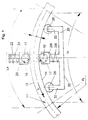
- FIG. 2 shows the measuring device integrated to capture the two arc lengths of the bent part in a typical three-roll bending machine with bending rolls 35 to 37.
- the main difference to the execution 1 is that the measuring unit in FIG. 2 has no guide bar 22 with guide rollers 26, the other version for the continuous radial Alignment of the measuring unit on the bent part ensures. Instead, the common linear guide 22 on the machine body after previous alignment either in steps adjustable - or not adjustable - attached.
- the linear guide 22 can either be behind the bending roller 37 or even just before the bending roller 37 in the feed direction x seen, i.e. in the space between middle role 35 and bending roller 37 are positioned.
Description
Die Erfindung betrifft ein Verfahren zum Feststellen von Radien bei -- zwei Zylinderflächen bestimmenden -- Biegeteilen, wobei eine innere Zylinderfläche einem Krümmungsmittelpunkt zugewandt sowie eine zweite -- äußere -- Zylinderfläche diesem abgewandt ist. Zudem erfaßt die Erfindung eine für dieses Verfahren besonders geeignete Vorrichtung.The invention relates to a method for determining Radii in - bending parts defining - two cylinder surfaces, an inner cylindrical surface having a center of curvature facing as well as a second - outer - cylinder surface this is turned away. The invention also covers a device particularly suitable for this method.
Eine tragbare Vorrichtung zum Biegen von Rohren ist beispielhaft der DE-PS 32 09 539 zu entnehmen. Eine Messung der Krümmung kann beispielsweise von Hand mittels eines Dreipunktmeßgerätes erfolgen.A portable device for bending pipes is an example can be found in DE-PS 32 09 539. A measurement the curvature can be done, for example, by hand using a Three-point measuring device.
Bei einem segmentförmigen Ausschnitt eines derart gekrümmten Gegenstandes mit konstantem Radius weist die dem Mittelpunkt zugewandte Zylinderfläche eine der Krümmung und der Gegenstandsbreite proportional kleinere Bogenlänge auf als die andere -- dem Mittelpunkt abgewandte -- äquidistant gekrümmte Zylinderfläche. Zwar lassen sich Radien gekrümmter Gegenstände beispielsweise mit der sog. Dreipunktmeßmethode, mit Dehnungsmeßstreifen sowie mit Meßverfahren feststellen, bei denen -- berührend oder berührungslos -- mehrere Punkte einer Kontur erfaßt und daraus der Radius errechnet wird (siehe zum beispiel GB-A-2087561), jedoch sind viele dieser Methoden entweder relativ ungenau oder an Randbedingungen gebunden, die in der Praxis kaum einzuhalten sind.In the case of a segment-shaped section of a curved section of this type Object with constant radius points to the center facing cylinder surface one of the curvature and smaller arc length proportional to the object width than the other - facing away from the center - equidistant curved cylinder surface. Radii can be curved Objects, for example with the so-called three-point measuring method, using strain gauges and measuring methods, where - touching or non-contact - several Detects points on a contour and uses this to calculate the radius becomes (see for example GB-A-2087561), however, many of these methods are either relatively imprecise or tied to boundary conditions that in can hardly be followed in practice.
In Kenntnis dieses Standes der Technik hat sich der Erfinder das Ziel gesetzt, ein Meßverfahren und eine Vorrichtung dazu zu entwickeln, mit deren Hilfe der Radius des Bogens von Biegeteilen mittels weniger und einfach erfaßbarer geometrischer Größen bestimmt zu werden vermag. The inventor was aware of this state of the art set the goal, a measuring method and a device to develop with the help of the radius of the arc of bent parts by means of fewer and easy to grasp geometrical Sizes can be determined.
Erfindungsgemäß ist diese aufgabe durch das im Patentanspruch 1
definierte.
Verfahren bzw. durch die im Patentanspruch 5 definierte
vorrichtung gelöst;
die Unteransprüche geben günstige Weiterbildungen
an.According to the invention, this object is achieved in
Erfindungsgemäß wird die Länge des Radius der dem Krümmungsmittelpunkt
näherliegenden inneren Zylinderfläche als
Quotient aus dem radialen Abstand der beiden Zylinderflächen
als Divident und einen Divisor bestimmt, der die Differenz
des Quotienten der Bogenlänge der äußeren Zylinderfläche
durch die Bogenlänge der inneren Zylinderfläche abzüglich
des Subtrahenden 1 ist. Dazu werden durch drei Meßwertaufnehmer
die folgenden Größen erfaßt: die Bogenlänge
La der äußeren Zylinderfläche, die Bogenlänge Li der inneren
Zylinderfläche sowie der radiale Abstand der beiden Zylinderflächen
voneinander. Dadurch läßt sich mittels der
nachstehenden Formel der Radius Ri des inneren Bogens berechnen:
Die Bestimmung der drei geometrischen Größen erfolgt mittels zweier -- bevorzugt baugleicher -- Reibrad-Drehgeber-Einheiten, welche einander gegenüber angeordnet sind; jede dieser Einheiten ist auf einem gesonderten Schlitten montiert, und beide Schlitten können voneinander unabhängig auf einer gemeinsam Linearführung bewegt werden. Jedem dieser Schlitten ist ein Kraftspeicher, insbesondere eine Druckfeder, zugeordnet. Dank dieser Maßgabe ist eine kontinuierliche Anlage der Reibräder am gebogenen Gegenstand gewährleistet; dieser befindet sich zwischen den beiden geschilderten Reibrädern. Jene kontinuierliche Anlage der Reibräder wird noch durch die Maßgabe unterstützt, daß die Druckfeder des äußeren Schlittens mit einer höheren Kraft ausgestattet ist als die Druckfeder des inneren Schlittens. The three geometric sizes are determined using two - preferably identical - friction wheel encoder units, which are arranged opposite each other; each this unit is mounted on a separate carriage, and both sledges can be independent of each other be moved on a common linear guide. Each one of these Sled is an energy store, especially one Compression spring, assigned. Thanks to this requirement is a continuous Ensure that the friction wheels rest on the curved object; this is between the two described Friction wheels. That continuous plant of Friction wheels are supported by the proviso that the Compression spring of the outer slide with a higher force is equipped as the compression spring of the inner slide.
Gemäß der Erfindung kann der Abstand zwischen den Zylinderflächen mit einem an sich bekannten Wegaufnehmer in einer Biegemaschine oder außerhalb dieser -- beispielsweise mit einem Handmeßgerät -- am gebogenen Teil gemessen werden.According to the invention, the distance between the Cylinder surfaces with a displacement transducer known per se in a bending machine or outside of it - for example with a handheld meter - be measured on the bent part.
Als günstig hat es sich erwiesen, die Linearführung mit einem zu ihr rechtwinkelig angeordneten Führungsbalken zu verbinden und an den freien Enden des Führungsbalkens jeweils eine Führungsrolle vorzusehen. Diese kann bei einem besonderen Ausführungsbeispiel an einem Tragarm des Führungsbalkens gelagert sein.It has proven to be cheap to use the linear guide with a to the right-angled guide bar connect and at the free ends of the guide beam each to provide a leadership role. This can be with a special embodiment on a support arm of the guide beam be stored.
Von Bedeutung für das erfindungsgemäße Verfahren ist zudem, daß beim Biegen in mehreren Umformstufen die Bogenlängen auch ohne eine radiale Ausrichtung des Führungsbalkens gemessen werden können. Da während einer Umformstufe die Lage des Biegeteils relativ zu den Reibrad-Drehgebereinheiten konstant bleibt, werden zwei zusammengehörende Bogenlängen gemessen, die eine Radienbestimmung ermöglichen.It is also important for the method according to the invention that that when bending in several stages, the arc lengths measured even without a radial alignment of the guide bar can be. As the situation during a forming stage of the bent part relative to the friction wheel encoder units remains constant, two arc lengths belonging together measured, which allow a radius determination.
Gemäß der Erfindung kann der Abstand zwischen den Schlitten auch durch einen Wegaufnehmer erfaßt werden; dieser Abstand entspricht der Breite des gebogenen Gegenstandes. According to the invention, the distance between the carriage can also be detected by a displacement sensor; this Distance corresponds to the width of the curved object.
Weitere Vorteile, Merkmale und Einzelheiten der Erfindung ergeben sich aus der nachfolgenden Beschreibung bevorzugter Ausführungsbeispiele sowie anhand der Zeichnungen; diese zeigen in ihren beiden Figuren schematische Draufsichten auf eine erfindungsgemäße Vorrichtung.Further advantages, features and details of the invention result from the following description more preferred Exemplary embodiments and with reference to the drawings; this show schematic plan views in their two figures a device according to the invention.
Bei einem durch Biegeumformung eines geraden Profils gebogenen
Stab 10 entspricht die Entfernung von dessen äußerer
Seitenfläche 12 zu dem in der Zeichnung nicht erkennbaren
Krümmungsmittelpunkt der Summe aus der Stabbreite b und dem
inneren Biegeradius Ri, also der Entfernung der inneren
Seitenfläche 14 zu jenem Krümmungsmittelpunkt. Jede der
beiden Seitenflächen 12,14 bestimmt einen von zwei zueinander
äquidistanten Zylinderflächenabschnitten.In the case of a bent profile by bending a
Zum Festlegen des inneren Biegeradius Ri erfassen drei Meßwertaufnehmer
die folgenden Größen:
sowie
such as
Mit Hilfe der folgenden Formel läßt sich dann beispielsweise
der Radius Ri des inneren Bogens berechnen:
Die Erfassung der drei geometrischen Größen wird in der
Weise vorgenommen, daß die Bogenlängen La, Li mittels eines
äußeren und eines inneren Reibrad-Drehgebers 16 bzw. 18 sowie
der Abstand b zwischen den beiden Zylinder- oder Seitenflächen
12,14 durch einen potentiometrischen Wegaufnehmer
festgestellt werden. The acquisition of the three geometric sizes is in the
Made that the arc lengths La, Li by means of a
outer and an inner
Die Reibrad-Drehgeber 16,18 befinden sich auf zwei Schlitten
20,20i, die sich unabhängig voneinander auf einer radial
zum Bogensegment ausgerichteten Linearführung 22 bewegen
können. Ein kontinuierliches Anlegen der Reibräder 17 jener
Reibrad-Drehgeber-Einheiten 16,18 an jenen Seitenflächen
12,14 wird mit zwei Druckfedern 24,24i erreicht, die sich
jeweils einends am Schlitten 24 bzw. 24i abstützen. Da die
äußere Druckfeder 24 eine höhere Kraft auf ihren Schlitten
20 ausübt als die innere Druckfeder 24i auf den inneren
Schlitten 20i, wird gleichzeitig ein kontinuierliches Anlegen
von Führungsrollen 26 am gekrümmten Stab 10 erreicht.The friction wheel
Die Führungsrollen 26 sind an den Enden zweier -- jeweils
von einem Teil eines Führungsbalkens 28 angebotener -- Seitenarme
eines in Draufsicht T-förmigen Führungsbaumes 30
festgelegt, dessen Mittelbalken jene Linearführung 22 bildet.
Deren notwendige radiale Ausrichtung wird mit dem von
ihr rechtwinkelig abstehenden Führungsbalken 28 erreicht,
von dessen freien Enden jeweils ein -- zur Linearführung
paralleler -- Lagerarm 32 für jene Führungsrollen 26 abragt.The
Das Ausführungsbeispiel der Fig. 2 zeigt die Meßvorrichtung
zum Erfassen der beiden Bogenlängen des Biegeteils integriert
in eine typische Drei-Rollen-Biegemaschine mit Biegerollen
35 bis 37. Der wesentliche Unterschied zur Ausführung
der Fig. 1 besteht darin, daß die Meßeinheit in Fig. 2
keinen Führungsbalken 22 mit Führungsrollen 26 aufweist,
der bei der anderen Ausführung für die kontinuierliche radiale
Ausrichtung der Meßeinheit auf dem Biegeteil sorgt.
Statt dessen wird die gemeinsame Linearführung 22 am Maschinenkorpus
nach vorherigem Ausrichten entweder in Stufen
verstellbar -- oder nicht verstellbar -- befestigt.The embodiment of FIG. 2 shows the measuring device
integrated to capture the two arc lengths of the bent part
in a typical three-roll bending machine with
Dabei kann die Linearführung 22 entweder hinter der Biegerolle
37 oder sogar kurz vor der Biegerolle 37 in Vorschubrichtung
x gesehen, d.h. in dem Raum zwischen Mittelrolle
35 und Biegerolle 37 positioniert werden. The
Nachdem das Biegeteil im ersten Umformschritt auf den Radius
Ri gebogen wurde, erfolgt bei Biegevorgängen, bei denen
in mehreren Schritten die fertige Kontur des Biegeteils erzeugt
wird, eine Zustellung der Biegerolle 37 so, daß sich
der Abstand zwischen Biegerolle 37 und Mittelrolle 35 verringert.After the bent part in the first forming step on the radius
Ri has been bent takes place during bending processes in which
The finished contour of the bent part is created in several steps
is, a delivery of the
Wenn danach das auf Ri gebogene Teil durch den Antrieb der
Rollen 35 bis 37 eine Bewegung in x-Richtung erfährt, verändert
sich der Biegeradius von Ri auf Ro < Ri. Nach einer
kurzen Anlaufphase bleibt die Anordnung des Biegeteils während
des restlichen Biegevorganges relativ zu den Biegerollen
35 bis 37 und insbesondere zu der Meßeinheit unverändert.
Bei einem Meßvorgang, der nach der Anlaufphase beginnt,
werden die zugehörigen Bogenlängen La und Li mit der
dargestellten Einheit erfaßt, ohne daß diese Einheit radial
auf dem Biegeteil ausgerichtet sein muß.If afterwards the part bent on Ri by the drive of the
Claims (17)
- Procedure to establish the radii of bending parts (10) determined by two surfaces of a cylinder where one inner surface of a cylinder (14) is turned towards a centre of curvature and a second surface of a cylinder (12) is turned away from it,
characterised by the fact
that the length of the radius (Ri) of the surface of a cylinder (14) laying nearer to the centre of curvature is determined by the quotient of the radial distance (b) of both surfaces of a cylinder (14, 12) as the divident and a divisor which is the difference of the quotient of the curve length (La) of the outer surface of a cylinder and the curve length (Li) of the inner surface of a cylinder minus the subtrahend 1. - Procedure according to claim 1, characterised by the fact that the radial distance (b) between the surfaces of the cylinders (12, 114) is measured after established the curve lengths (Li, La) have been established.
- Procedure according to claim 1 or 2, characterised by the fact that, while bending, the curve lengths (Li, La) are measured independently from the radial orientation in several deformation phases.
- Procedure according to one of the claims 1 to 3, characterised by the fact that at least one of the curve lengths (Li, La) is measured using a contactless method.
- Device to perform the measuring method according to one of the claims 1 to 4, characterised by the fact that two friction wheel encoder units (16, 18) define an inner width for the bending part (10), where each of the friction wheel encoder units is mounted on a slide (20,20 i) and both slides can be moved on a common linear guide (22). The linear guide (22) can be radially oriented with reference to the curved bending part (10) being in the inner width.
- Device according to claim 5, characterised by the fact that each slide (20, 20i) supports itself against an energy accumulator (24, 24i) at the side which is turned away from the bending part (10).
- Device according to claim 5 or 6, characterised by the fact that the linear guide (22) is part of a guiding way (30) containing a traversing guiding arm (28) at the free ends of which one each guiding roller (26) is mounted for the bending part.
- Device according to one of the claims 5 to 7, characterised by the fact that the guiding arm (28) is bent in itself.
- Device according to claim 7, characterised by the fact that the that the guiding arm (28) is in rectangular position with reference to the linear guide (22).
- Device according to one of the claims 7 to 9, characterised by the fact that from the free ends of the guiding arm (28) one each bracket (32) for a guiding roller is point is pointing down .
- Device according to claim 10, characterised by the fact that the guiding arm (32) runs approximately parallel along the linear guide (22).
- Device according to one of the claims 6 to 11, characterised by the fact that the accumulator of energy of the slide (20) laying radial outside is provided with more power than the accumulator of energy (24i) of the slide (20i) laying radial inside.
- Device according to one of the claims 5 to 12, characterised by a distance sensor to determine the distance (b) between the slides (20, 20i) respectively the surfaces of the cylinders (12, 14) of the bending part.
- Device according to one of the claims 5 to 13, characterised by the fact that the slides (20, 20i) in conveying direction (x) at both sides of the movement path are at least one circumference of a roller (35, 36, 37) behind the bending part (10).
- Device according to one of the claims 5 to 14, characterised by the fact that the common linear guide (22) with the slides (20, 20i) are mounted in the space between a centre roller (35) and a bending roller (37), preferably in feed direction (x) short in front of the bending roller.
- Device according to one of the claims 14 or 15, characterised by the fact that at the inner side of curvature of the bending part (10) a centre roller (35) is foreseen. At the outside of the curvature a guiding roller (36) and a bending roller (37) near to the guide subtend the centre roller.
- Device according to one of the claims 14 to 16, characterised by the fact that the guiding roller (36) and the bending roller (37)are mounted at different sides of a diametrical centre axle (Q) laid through the centre (M) of the centre roller (35).
Applications Claiming Priority (2)
| Application Number | Priority Date | Filing Date | Title |
|---|---|---|---|
| DE19536938 | 1995-10-04 | ||
| DE19536938 | 1995-10-04 |
Publications (3)
| Publication Number | Publication Date |
|---|---|
| EP0767016A2 EP0767016A2 (en) | 1997-04-09 |
| EP0767016A3 EP0767016A3 (en) | 1997-12-03 |
| EP0767016B1 true EP0767016B1 (en) | 1999-06-02 |
Family
ID=7773990
Family Applications (1)
| Application Number | Title | Priority Date | Filing Date |
|---|---|---|---|
| EP19960115724 Expired - Lifetime EP0767016B1 (en) | 1995-10-04 | 1996-10-01 | Method and apparatus for measuring the radius of bent products |
Country Status (2)
| Country | Link |
|---|---|
| EP (1) | EP0767016B1 (en) |
| DE (1) | DE19602504A1 (en) |
Families Citing this family (6)
| Publication number | Priority date | Publication date | Assignee | Title |
|---|---|---|---|---|
| IT1394105B1 (en) * | 2009-05-06 | 2012-05-25 | Cml Int Spa | MACHINE TO TURN CONTINUOUSLY AN EXTENDED PIECE ACCORDING TO PREDETERMINATED RAYS |
| IT1400500B1 (en) * | 2010-06-22 | 2013-06-11 | Crippa Spa | PROCEDURE FOR THE BENDING OF TUBES, WIRES OR TAPES OF METAL A SERPENTINA OR SPRING AND CURVED MACHINE TUBES, WIRES OR METAL TAPES FOR THE MANUFACTURE OF A SERPENTINE OR A SPRING PRESENTING A PERFORMANCE WITH A PROPELLER INCLUDING A PLURALITY OF LOOPS |
| ITTO20130936A1 (en) | 2013-11-19 | 2015-05-20 | Cte Sistemi Srl | MEASUREMENT GROUP FOR MEASURING THE CURVARY RADIUS AND ADVANCEMENT IN A BENDING MACHINE, IN PARTICULAR IN A BENDING MACHINE FOR BENDING CONDUCTORS FOR SUPERCONDUCTIVE ROLLS |
| DE102016013144A1 (en) * | 2016-10-31 | 2018-05-03 | Technische Universität Dortmund | Device for tactile detection and analysis of the geometry of curved profiles or tubes |
| DE102020127164B3 (en) * | 2020-10-15 | 2021-07-15 | Jenoptik Industrial Metrology Germany Gmbh | Radial force device for a contour measuring device and measuring system |
| CN113884958B (en) * | 2021-09-27 | 2023-07-25 | 中国科学院合肥物质科学研究院 | Device and method for measuring critical lateral bending radius of superconducting strip |
Family Cites Families (5)
| Publication number | Priority date | Publication date | Assignee | Title |
|---|---|---|---|---|
| CH572200A5 (en) * | 1973-09-18 | 1976-01-30 | Haeusler Christian Ag | |
| DE3041212C2 (en) * | 1980-11-03 | 1982-08-26 | August Wilhelm 5901 Wilnsdorf Schäfer | Device for bending, in particular rounding sheet metal or profiles |
| GB2087561A (en) * | 1980-11-11 | 1982-05-26 | Smt Pullmax | Apparatus for measuring the curvature of a single-curved surface |
| US4532787A (en) * | 1981-03-16 | 1985-08-06 | C.M.L. Costruzioni Meccaniche Liri S.R.L. | Portable electromechanically-controlled pipe-bending apparatus |
| DE4225878C2 (en) * | 1992-08-05 | 1996-02-29 | Bayer Isolierglasfab Kg | Method and device for bending a sheet on a hollow spacer profile |
-
1996
- 1996-01-25 DE DE19602504A patent/DE19602504A1/en not_active Withdrawn
- 1996-10-01 EP EP19960115724 patent/EP0767016B1/en not_active Expired - Lifetime
Also Published As
| Publication number | Publication date |
|---|---|
| EP0767016A3 (en) | 1997-12-03 |
| EP0767016A2 (en) | 1997-04-09 |
| DE19602504A1 (en) | 1997-04-10 |
Similar Documents
| Publication | Publication Date | Title |
|---|---|---|
| EP0916425B1 (en) | Apparatus for straightening a rolled section | |
| EP0494430B1 (en) | Method for measuring the diameter of cylinders, particularly of drums | |
| EP2093537A1 (en) | Process and device for the determination of the alignment of two rotatable machine parts, of the alignment of two hollow cylindrical machine parts, or for the examination of a component for straightness | |
| DE2704122C2 (en) | Pressure device for a wire winding machine | |
| EP0767016B1 (en) | Method and apparatus for measuring the radius of bent products | |
| DE19502918B4 (en) | Apparatus for the continuous production of longitudinally welded thin-walled helical or annular corrugated metal pipes | |
| DE102008035480A1 (en) | Surfaces i.e. flange surfaces, measuring method for pipe, involves determining shape and/or position relations between surfaces in computerized and automated manner by evaluation of position values, value differences and/or value curves | |
| DE3211489A1 (en) | METHOD AND DEVICE FOR CORRECTING SETPOINT DIFFERENCES OF PLATFORMALLY DEFORMABLE OBJECTS | |
| AT506313A4 (en) | BENDING BENCH FOR A BENDING PEPPER, IN PARTICULAR BUTTING PRESSURE | |
| EP3517923B1 (en) | Propulsion device for inspection system | |
| DE3817387A1 (en) | METHOD AND DEVICE FOR DETECTING THE EXTERNAL DESIGN OF A LONG STRETCHED, CROSS-SECTION PRISMATIC BODY | |
| EP0033310A1 (en) | Measuring arrangement provided at a roller-way formed by rotatably mounted rollers and evaluation method of the measured value | |
| EP1218122A1 (en) | Straightening machine for straightening elongated bodies | |
| DE102005013746B4 (en) | Back corrugated Roll | |
| WO1989009104A1 (en) | Process and device for bending preferably rod-shaped material | |
| DE3322777A1 (en) | Method for straightening, in particular bending-straightening and/or twisting-straightening, of workpieces | |
| DE3025320A1 (en) | METHOD AND DEVICE FOR FEEDING ROD MATERIAL BY PRESET LENGTHS | |
| EP2336406A1 (en) | Carding wire mounting device for metal wire | |
| DE2362805B2 (en) | Transducer arrangement | |
| EP0384477A2 (en) | Method and machine for bending tubes | |
| WO2022017969A1 (en) | Wire conveyor device and method | |
| DE102019205798A1 (en) | Tracking control for an induction hardening system | |
| DE3815304A1 (en) | Method and apparatus for bending or straightening sections and strips by means of rolls or rollers | |
| DE19510330C2 (en) | Bending device | |
| WO2011020867A1 (en) | Measuring apparatus and method for measuring large components |
Legal Events
| Date | Code | Title | Description |
|---|---|---|---|
| PUAI | Public reference made under article 153(3) epc to a published international application that has entered the european phase |
Free format text: ORIGINAL CODE: 0009012 |
|
| AK | Designated contracting states |
Kind code of ref document: A2 Designated state(s): CH FR IT LI NL SE |
|
| PUAL | Search report despatched |
Free format text: ORIGINAL CODE: 0009013 |
|
| AK | Designated contracting states |
Kind code of ref document: A3 Designated state(s): CH FR IT LI NL SE |
|
| 17P | Request for examination filed |
Effective date: 19980416 |
|
| GRAG | Despatch of communication of intention to grant |
Free format text: ORIGINAL CODE: EPIDOS AGRA |
|
| GRAG | Despatch of communication of intention to grant |
Free format text: ORIGINAL CODE: EPIDOS AGRA |
|
| GRAH | Despatch of communication of intention to grant a patent |
Free format text: ORIGINAL CODE: EPIDOS IGRA |
|
| 17Q | First examination report despatched |
Effective date: 19980805 |
|
| GRAH | Despatch of communication of intention to grant a patent |
Free format text: ORIGINAL CODE: EPIDOS IGRA |
|
| GRAA | (expected) grant |
Free format text: ORIGINAL CODE: 0009210 |
|
| AK | Designated contracting states |
Kind code of ref document: B1 Designated state(s): CH FR IT LI NL SE |
|
| PG25 | Lapsed in a contracting state [announced via postgrant information from national office to epo] |
Ref country code: SE Free format text: THE PATENT HAS BEEN ANNULLED BY A DECISION OF A NATIONAL AUTHORITY Effective date: 19990602 Ref country code: NL Free format text: LAPSE BECAUSE OF FAILURE TO SUBMIT A TRANSLATION OF THE DESCRIPTION OR TO PAY THE FEE WITHIN THE PRESCRIBED TIME-LIMIT Effective date: 19990602 Ref country code: IT Free format text: LAPSE BECAUSE OF FAILURE TO SUBMIT A TRANSLATION OF THE DESCRIPTION OR TO PAY THE FEE WITHIN THE PRESCRIBED TIME-LIMIT;WARNING: LAPSES OF ITALIAN PATENTS WITH EFFECTIVE DATE BEFORE 2007 MAY HAVE OCCURRED AT ANY TIME BEFORE 2007. THE CORRECT EFFECTIVE DATE MAY BE DIFFERENT FROM THE ONE RECORDED. Effective date: 19990602 Ref country code: FR Free format text: LAPSE BECAUSE OF FAILURE TO SUBMIT A TRANSLATION OF THE DESCRIPTION OR TO PAY THE FEE WITHIN THE PRESCRIBED TIME-LIMIT Effective date: 19990602 |
|
| REG | Reference to a national code |
Ref country code: CH Ref legal event code: EP |
|
| EN | Fr: translation not filed | ||
| PLBE | No opposition filed within time limit |
Free format text: ORIGINAL CODE: 0009261 |
|
| STAA | Information on the status of an ep patent application or granted ep patent |
Free format text: STATUS: NO OPPOSITION FILED WITHIN TIME LIMIT |
|
| 26N | No opposition filed | ||
| PG25 | Lapsed in a contracting state [announced via postgrant information from national office to epo] |
Ref country code: LI Free format text: LAPSE BECAUSE OF NON-PAYMENT OF DUE FEES Effective date: 20001031 Ref country code: CH Free format text: LAPSE BECAUSE OF NON-PAYMENT OF DUE FEES Effective date: 20001031 |
|
| REG | Reference to a national code |
Ref country code: CH Ref legal event code: PL |