EP0765202B1 - Drilling tool with internal cavities for chip removal - Google Patents
Drilling tool with internal cavities for chip removal Download PDFInfo
- Publication number
- EP0765202B1 EP0765202B1 EP95922819A EP95922819A EP0765202B1 EP 0765202 B1 EP0765202 B1 EP 0765202B1 EP 95922819 A EP95922819 A EP 95922819A EP 95922819 A EP95922819 A EP 95922819A EP 0765202 B1 EP0765202 B1 EP 0765202B1
- Authority
- EP
- European Patent Office
- Prior art keywords
- chip
- insert
- drill body
- drill
- inserts
- Prior art date
- Legal status (The legal status is an assumption and is not a legal conclusion. Google has not performed a legal analysis and makes no representation as to the accuracy of the status listed.)
- Expired - Lifetime
Links
Images


Classifications
-
- B—PERFORMING OPERATIONS; TRANSPORTING
- B23—MACHINE TOOLS; METAL-WORKING NOT OTHERWISE PROVIDED FOR
- B23B—TURNING; BORING
- B23B51/00—Tools for drilling machines
-
- E—FIXED CONSTRUCTIONS
- E21—EARTH OR ROCK DRILLING; MINING
- E21B—EARTH OR ROCK DRILLING; OBTAINING OIL, GAS, WATER, SOLUBLE OR MELTABLE MATERIALS OR A SLURRY OF MINERALS FROM WELLS
- E21B10/00—Drill bits
- E21B10/60—Drill bits characterised by conduits or nozzles for drilling fluids
-
- B—PERFORMING OPERATIONS; TRANSPORTING
- B23—MACHINE TOOLS; METAL-WORKING NOT OTHERWISE PROVIDED FOR
- B23B—TURNING; BORING
- B23B51/00—Tools for drilling machines
- B23B51/04—Drills for trepanning
- B23B51/0486—Drills for trepanning with lubricating or cooling equipment
- B23B51/0493—Drills for trepanning with lubricating or cooling equipment with exchangeable cutting inserts, e.g. able to be clamped
-
- B—PERFORMING OPERATIONS; TRANSPORTING
- B23—MACHINE TOOLS; METAL-WORKING NOT OTHERWISE PROVIDED FOR
- B23B—TURNING; BORING
- B23B2251/00—Details of tools for drilling machines
- B23B2251/02—Connections between shanks and removable cutting heads
-
- B—PERFORMING OPERATIONS; TRANSPORTING
- B23—MACHINE TOOLS; METAL-WORKING NOT OTHERWISE PROVIDED FOR
- B23B—TURNING; BORING
- B23B2251/00—Details of tools for drilling machines
- B23B2251/56—Guiding pads
-
- B—PERFORMING OPERATIONS; TRANSPORTING
- B23—MACHINE TOOLS; METAL-WORKING NOT OTHERWISE PROVIDED FOR
- B23B—TURNING; BORING
- B23B2270/00—Details of turning, boring or drilling machines, processes or tools not otherwise provided for
- B23B2270/30—Chip guiding or removal
-
- B—PERFORMING OPERATIONS; TRANSPORTING
- B23—MACHINE TOOLS; METAL-WORKING NOT OTHERWISE PROVIDED FOR
- B23B—TURNING; BORING
- B23B51/00—Tools for drilling machines
- B23B51/06—Drills with lubricating or cooling equipment
- B23B51/063—Deep hole drills, e.g. ejector drills
-
- Y—GENERAL TAGGING OF NEW TECHNOLOGICAL DEVELOPMENTS; GENERAL TAGGING OF CROSS-SECTIONAL TECHNOLOGIES SPANNING OVER SEVERAL SECTIONS OF THE IPC; TECHNICAL SUBJECTS COVERED BY FORMER USPC CROSS-REFERENCE ART COLLECTIONS [XRACs] AND DIGESTS
- Y10—TECHNICAL SUBJECTS COVERED BY FORMER USPC
- Y10T—TECHNICAL SUBJECTS COVERED BY FORMER US CLASSIFICATION
- Y10T408/00—Cutting by use of rotating axially moving tool
- Y10T408/44—Cutting by use of rotating axially moving tool with means to apply transient, fluent medium to work or product
- Y10T408/45—Cutting by use of rotating axially moving tool with means to apply transient, fluent medium to work or product including Tool with duct
-
- Y—GENERAL TAGGING OF NEW TECHNOLOGICAL DEVELOPMENTS; GENERAL TAGGING OF CROSS-SECTIONAL TECHNOLOGIES SPANNING OVER SEVERAL SECTIONS OF THE IPC; TECHNICAL SUBJECTS COVERED BY FORMER USPC CROSS-REFERENCE ART COLLECTIONS [XRACs] AND DIGESTS
- Y10—TECHNICAL SUBJECTS COVERED BY FORMER USPC
- Y10T—TECHNICAL SUBJECTS COVERED BY FORMER US CLASSIFICATION
- Y10T408/00—Cutting by use of rotating axially moving tool
- Y10T408/89—Tool or Tool with support
- Y10T408/905—Having stepped cutting edges
- Y10T408/906—Axially spaced
-
- Y—GENERAL TAGGING OF NEW TECHNOLOGICAL DEVELOPMENTS; GENERAL TAGGING OF CROSS-SECTIONAL TECHNOLOGIES SPANNING OVER SEVERAL SECTIONS OF THE IPC; TECHNICAL SUBJECTS COVERED BY FORMER USPC CROSS-REFERENCE ART COLLECTIONS [XRACs] AND DIGESTS
- Y10—TECHNICAL SUBJECTS COVERED BY FORMER USPC
- Y10T—TECHNICAL SUBJECTS COVERED BY FORMER US CLASSIFICATION
- Y10T408/00—Cutting by use of rotating axially moving tool
- Y10T408/89—Tool or Tool with support
- Y10T408/909—Having peripherally spaced cutting edges
Definitions
- the present invention relates to a drilling tool for chip-breaking machining of metallic materials according to claim 1 and as known for example from DE-A-2316762.
- a drilling tool for chip-breaking machining of metallic materials according to claim 1 and as known for example from DE-A-2316762.
- Such a tool primarily is intended for so called ejector drilling. However, it may also advantageously be used for so called BTA-drilling.
- a drill body primarily for ejector drilling is described. It consists of a substantially cylindrical, tube shaped part, with a substantially cylindrical cavity extending from the one end to close to the operative drill head at the other end.
- the drill head is provided with one or more cemented carbide cutting inserts, which are soldered or brazed in insert pockets provided for this purpose.
- the drill body consists of one single piece wherein the drill head includes two branch channels leading down from the cutting insert area into the central cylindrical cavity.
- a drilling tool comprising a drill body on which two or more cutting inserts are mounted.
- the inserts are substantially formed as parallel-trapezoids and are axially mounted, i.e., the abutment surfaces of the cutting inserts extend axially, the inserts suitably being fixed by brazing.
- this drill body has sometimes caused chip jamming in the area where the two chip canals and the central hole meet.
- the drill body consists of two parts which are joined by welding, namely the drill head as such or the drill crown, and the cylindrical, partly threaded part.
- This weld joint in combination with the fact that the drill crown has been cast, has with a certain frequency resulted in an imperfect roundness of the final product. This has in turn implied that some customers have required a finishing grinding in order to attain a perfect roundness and rotation symmetry around the central axis, which unnecessarily increases the production cost of the drill.
- a further drawback of this weld joint has turned out to be that chips occasionally get stuck in the weld joint, since in practice a weld joint is never fully through but leaves a certain gap on the interior side. It is often enough that one single chip gets wedged to make the following chips pile up and cause chip jamming and in worst case a tool breakdown.
- a primary object of the present invention is to provide a drill body, particularly a drill body for ejector drilling, that practically eliminates any risk for chip jamming.
- a further object of the present invention is to eliminate any unevenness on the inside, in which a chip could get jammed.
- Another object of the present invention is to provide a drill body with practically perfect roundness.
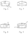
- a drilling tool of ejector type is generally designated by reference numeral 1.
- the tool comprises a drilling crown or head 2, an intermediate part 3 and a shaft 4.
- the shaft 4 is provided with an outer thread 5, which is intended to, in a way known per se , be fixed by threading it upon a fastening outer tube (not shown).
- An inner tube (not shown) that is concentrical with said outer tube is inserted in a way known per se into the inner, substantially cylindrical cavity of the drill, past the cooling medium holes 6, whereby formed chips follow the cutting medium through said inner tube.
- the top side of the drill head is provided with three cutting insert seats or pockets 7, 8 and 9 each intended to accommodate a drill cutting insert 10.
- the three cutting inserts are equal, the only difference being that the central cutting insert is reversed in comparison to the peripheral and intermediate cutting inserts.
- the number of cutting inserts in an ejector drill may be chosen between one and five.
- the disadvantage with one single cutting insert is that the cutting forces that the support pads have to endure become large since the drill becomes unbalanced. It has been found that the number of three is a good compromise between complicity, life and out-balancing.
- the ejector drill is usually produced as a one-way drill and the cemented carbide inserts according to figure 2 are therefore soldered or brazed in the cutting pockets. Since it is of one-way type, the drill should be worn as long as possible without the product quality and the cassation risk becoming disturbing.
- the periphery insert 10A determines the diameter of the drilled hole, which is usually between 20 and 65 mm. Radially inwardly the cutting edge of this insert is inclined upwardly.
- the adjacent central cutting insert 10C in the cutting pocket 8 overlaps the center axis of the drill, since no remaining core is desired. Contrary to the peripheral insert, axially downwardly its cutting edge is inclined radially inwardly, since otherwise the trailing cutting insert would be submitted to so large stress that it would very soon break.
- the head tip is provided with a conical recess 25.
- the intermediate cutting insert 10B is in the insert pocket 9.
- the revolution path of the cutting edge of the intermediate insert overlaps somewhat with both the cutting edges of the peripheral and the central cutting inserts, in order to obtain a continuous cutting line from the central axis to the periphery.
- the inserts may be either tangentially positioned, as illustrated in the appended figures, or axially positioned, as for instance disclosed in EP-A-491 670. However, they are preferably arranged in accordance with the appended figures.
- Two chip canals, ducts or flutes end in the top side of the drill: one common, larger chip canals 11 for the peripheral and the central inserts, and one somewhat smaller chip flute 12 for the intermediate cutting insert.
- the opposed, lower ends of these chip canals end in a turned-out inner chip space 13, which has a frustoconical shape, with the bottom surface turned upwards in direction towards the top side of the drill.
- the central and intermediate cutting inserts will be on a bridge-shaped device 14, that extends transversely over the space 13 and connects to two, substantially diametrically opposed parts of the drill's top side.
- this space 13 is turned by a turning tool being introduced through the opening or substantially cylindrical cavity 15 in the rear end side of the drill.
- This space 13 results in several advantages, of which may be mentioned increased chip space with minimized risk for chip jamming, and a lighter construction. It would be impossible to cast. However, thanks to the fact that the whole drill body is cast in one single turned piece, cavities may be formed which increase inwardly. The chip canals 11 and 12 have been milled out from above, from the drill's topside.
- the milling tool has been angled relative to the central axis of the drill, adjacent to the periphery of the drill, so that outwardly angled, bevelled surfaces have been obtained, which adjoin either to the immediate proximity of the outer envelope surface of the drill via a small land portion 16, or which directly form a break line 17 with said envelope surface.
- the combination effect should be evident of an integral drilling tool together with the turned-out chip space 13; namely that both cooperate to achieve maximal and fully unhindered chip flow.
- the chip space 13 were formed in a welded drill, the weld joint would be located on the conical envelope surface of said space, where the weld joint gap earlier or later would cause a wedging of a chip.
- the boring 15 would continue uniformly without any chip space 13, the available chip flow space would diminish and thereby the risk for chip jamming would increase.
- the rotation-symmetrical outer surface of the drill is suitably made by turning while the other external surface portions are formed by milling.
- the insert pockets or seats 7, 8 and 9 are made in the simplest possible way, namely by one single short, straight end milling operation per insert seat, with one and the same end mill.
- the rear abutment surface of the insert pocket gets a rounded, semi circle-formed shape corresponding to the cutting diameter of the end mill.
- the inner cavity 15 is bored, whereafter as mentioned above, the chip space 13 is turned out. It may be pointed out that also the part that is occupied by the chip space 13 before then consists of a continuous portion of the boring 15.
- figure 2 reproduces a cutting insert 10 according to the present invention.
- a cutting insert 10 comprises a relief surface 18 and a rounded edge side 19.
- the chip surface comprises an extended chip breaker 20 and below that a substantially plane chip surface portion 21.
- a distance knob 22 which sets aside any interferences when positioning the insert in the insert pocket due to unevennesses that may arise when the inserts are pressed.
- the distance knob 22 minimizes the risk for any positioning discrepancies caused by the varying thickness of the solder layer, by the fact that the contact between the two opposed semi circle-shaped surfaces becomes minimal.
- the rounded back of the cutting insert gives a considerably reduced risk for the formation of cracks, since it permits a favourable stress picture without any sham corners which involve stess concentrations. Further, since the length of the insert is large in comparison to the insert width, a larger support is obtained for taking up cutting forces. Moreover, the insert is very favourable at the pressing per se and does not cause any compacting problems whatsoever.
- the drill according to the invention is equipped with support pads 23, which are soldered or brazed in the support pad pockets 24. Also these support pad pockets are suitably milled out by one sole straight milling operation with an end mill, in the same way as the insert pockets 7, 8 and 9.
- the support pad may suitably have a matching shape, i.e., an elongated body with a rounded end.
- the outer side of the support pad is suitably given a rounded form, with the shape of a cylinder surface segment, in order to substantially conform to the substantially cylindrical envelope surface of the drill.
- the rounded rear abutment surface functions for guidance in the initial stage of the mourning, i.e., it permits a certain dislocation laterally, which is a necessity for automated mounting.
Landscapes
- Engineering & Computer Science (AREA)
- Mechanical Engineering (AREA)
- Geology (AREA)
- Life Sciences & Earth Sciences (AREA)
- Mining & Mineral Resources (AREA)
- Environmental & Geological Engineering (AREA)
- Fluid Mechanics (AREA)
- Physics & Mathematics (AREA)
- General Life Sciences & Earth Sciences (AREA)
- Geochemistry & Mineralogy (AREA)
- Drilling Tools (AREA)
- Earth Drilling (AREA)
- Perforating, Stamping-Out Or Severing By Means Other Than Cutting (AREA)
- Drilling And Boring (AREA)
Applications Claiming Priority (3)
| Application Number | Priority Date | Filing Date | Title |
|---|---|---|---|
| SE9402037 | 1994-06-13 | ||
| SE9402037A SE509383C2 (sv) | 1994-06-13 | 1994-06-13 | Borrverktyg |
| PCT/SE1995/000616 WO1995034398A1 (en) | 1994-06-13 | 1995-05-31 | Drilling tool with internal cavities for chip removal |
Publications (2)
| Publication Number | Publication Date |
|---|---|
| EP0765202A1 EP0765202A1 (en) | 1997-04-02 |
| EP0765202B1 true EP0765202B1 (en) | 2000-02-16 |
Family
ID=20394337
Family Applications (1)
| Application Number | Title | Priority Date | Filing Date |
|---|---|---|---|
| EP95922819A Expired - Lifetime EP0765202B1 (en) | 1994-06-13 | 1995-05-31 | Drilling tool with internal cavities for chip removal |
Country Status (14)
| Country | Link |
|---|---|
| US (1) | US5964553A (pl) |
| EP (1) | EP0765202B1 (pl) |
| JP (1) | JPH10501184A (pl) |
| KR (1) | KR100340397B1 (pl) |
| CN (1) | CN1059851C (pl) |
| AT (1) | ATE189785T1 (pl) |
| AU (1) | AU683394B2 (pl) |
| BR (1) | BR9508000A (pl) |
| CA (1) | CA2192580C (pl) |
| DE (1) | DE69515117T2 (pl) |
| PL (1) | PL178302B1 (pl) |
| RU (1) | RU2135331C1 (pl) |
| SE (1) | SE509383C2 (pl) |
| WO (1) | WO1995034398A1 (pl) |
Cited By (1)
| Publication number | Priority date | Publication date | Assignee | Title |
|---|---|---|---|---|
| CN106736657A (zh) * | 2017-02-28 | 2017-05-31 | 中兴能源装备有限公司 | 内排屑抗震刀杆 |
Families Citing this family (29)
| Publication number | Priority date | Publication date | Assignee | Title |
|---|---|---|---|---|
| CN1314506C (zh) * | 2001-07-03 | 2007-05-09 | 王峻 | 单出屑口内排屑喷吸钻 |
| US20040018064A1 (en) * | 2002-03-15 | 2004-01-29 | Liu Chunghorng R. | Cutting tools |
| SE526387C2 (sv) * | 2003-05-08 | 2005-09-06 | Seco Tools Ab | Borr för spånavskiljande bearbetning med alla delar utförda i ett material samt med innesluten spolkanal |
| SE0301456D0 (sv) * | 2003-05-20 | 2003-05-20 | Sandvik Ab | Ett eggbärande borrkropp, och ett förfarande för tillverkning av samt ett borrverktyg innefattande en dylik borrkropp |
| SE526676C2 (sv) * | 2003-05-20 | 2005-10-25 | Sandvik Intellectual Property | Eggbärande borrkropp för långhålsborrning med eggar förfärdigade i ett stycke med borrkroppen |
| JP4272021B2 (ja) * | 2003-09-12 | 2009-06-03 | ユニタック株式会社 | 深孔切削具 |
| JP4908900B2 (ja) * | 2006-04-07 | 2012-04-04 | ユニタック株式会社 | 深穴切削装置 |
| CN101730603B (zh) | 2007-06-29 | 2013-11-13 | 联合机械工程公司 | 喷吸钻系统 |
| IL187034A0 (en) * | 2007-10-30 | 2008-02-09 | Iscar Ltd | Cutting tool |
| JP5078731B2 (ja) * | 2008-04-25 | 2012-11-21 | ユニタック株式会社 | 深穴切削用スローアウェイチップ及び深穴切削用ドリルヘッド |
| JP2010000581A (ja) * | 2008-06-23 | 2010-01-07 | Yunitakku Kk | 深孔切削用ドリルヘッド |
| JP2010042493A (ja) * | 2008-08-18 | 2010-02-25 | Takuji Nomura | 複数ワークの連通穿孔方法 |
| RU2481925C2 (ru) * | 2011-02-21 | 2013-05-20 | Константин Эдуардович Огоньков | Крепежное устройство для режущих пластин |
| WO2012157063A1 (ja) * | 2011-05-16 | 2012-11-22 | Nomura Takuji | 深穴切削用ドリルヘッド |
| US9232952B2 (en) | 2012-04-16 | 2016-01-12 | Medtronic Ps Medical, Inc. | Surgical bur with non-paired flutes |
| CN102814526A (zh) * | 2012-08-30 | 2012-12-12 | 太原重工股份有限公司 | 一种钻深孔装置 |
| US9883873B2 (en) | 2013-07-17 | 2018-02-06 | Medtronic Ps Medical, Inc. | Surgical burs with geometries having non-drifting and soft tissue protective characteristics |
| US10335166B2 (en) | 2014-04-16 | 2019-07-02 | Medtronics Ps Medical, Inc. | Surgical burs with decoupled rake surfaces and corresponding axial and radial rake angles |
| DE102014111846A1 (de) * | 2014-08-19 | 2016-02-25 | Kennametal Inc. | Spiralbohrer mit Keramikeinsätzen |
| CN104526229B (zh) * | 2014-12-15 | 2016-04-13 | 哈尔滨理工大学 | 一种内排屑深孔钻刀片用焊接夹具及使用方法 |
| US9955981B2 (en) | 2015-03-31 | 2018-05-01 | Medtronic Xomed, Inc | Surgical burs with localized auxiliary flutes |
| US10265082B2 (en) | 2015-08-31 | 2019-04-23 | Medtronic Ps Medical, Inc. | Surgical burs |
| JP6620939B2 (ja) * | 2016-04-18 | 2019-12-18 | 株式会社NejiLaw | 切削用工具 |
| CN105772808A (zh) * | 2016-04-18 | 2016-07-20 | 哈尔滨理工大学 | 一种吸气式自排屑麻花钻头 |
| WO2019087656A1 (ja) * | 2017-10-30 | 2019-05-09 | 京セラ株式会社 | 切削工具及び切削加工物の製造方法 |
| CN110886758B (zh) * | 2018-09-10 | 2021-07-13 | 庆达科技股份有限公司 | 具低旋锁扭力的螺丝 |
| JP6835194B1 (ja) * | 2019-12-12 | 2021-02-24 | 株式会社タンガロイ | 穴あけ工具 |
| CN116220562B (zh) * | 2023-05-10 | 2023-07-14 | 北京中联勘工程技术有限责任公司 | 一种岩土工程勘察钻探装置 |
| CN116658083B (zh) * | 2023-08-01 | 2023-10-03 | 陕西星通石油工程技术有限公司 | 一种pdc钻头水眼防堵塞模块 |
Family Cites Families (14)
| Publication number | Priority date | Publication date | Assignee | Title |
|---|---|---|---|---|
| SE347450B (pl) * | 1969-11-24 | 1972-08-07 | Sandvikens Jernverks Ab | |
| DE2316762A1 (de) * | 1973-04-04 | 1974-10-17 | Heller Geb | Bohrwerkzeug mit innerem abfuehrkanal |
| US4108567A (en) * | 1975-01-20 | 1978-08-22 | Sandvik Aktiebolag | Boring tool |
| SE381592B (sv) * | 1975-01-20 | 1975-12-15 | Sandvik Ab | Borrverktyg |
| SE7710434L (sv) * | 1977-09-19 | 1979-03-20 | Sandvik Ab | Sker for spanskerande bearbetning |
| US4285618A (en) * | 1979-10-12 | 1981-08-25 | Shanley Stephen E Jr | Rotary milling cutter |
| DE3611999A1 (de) * | 1986-04-09 | 1987-10-15 | Guehring Gottlieb Fa | Zwei- oder mehrschneidiges bohrwerkzeug mit austauschbaren schneidelementen |
| SU1572765A1 (ru) * | 1988-03-09 | 1990-06-23 | Одесский Политехнический Институт | Инструмент дл обработки отверстий |
| SE468930B (sv) * | 1989-06-09 | 1993-04-19 | Sandvik Ab | Borr med axiella spaankanaler i vilka haardlister aer foersaenkta |
| SE502199C2 (sv) * | 1990-12-19 | 1995-09-11 | Sandvik Ab | Borrskär med snedställd främre skäregg samt borrverktyg för detta |
| US5146669A (en) * | 1991-07-31 | 1992-09-15 | Fabiano Joseph F | Method of manufacturing an insert drill |
| SE500824C2 (sv) * | 1993-01-15 | 1994-09-12 | Sandvik Ab | Långhålsborr med skär av titanbaserad karbonitridlegering |
| US5401209A (en) * | 1993-01-15 | 1995-03-28 | Ripol; George J. | Current regulated electronic stunning apparatus |
| SE504331C2 (sv) * | 1994-09-12 | 1997-01-13 | Sandvik Ab | Stödlist för borr |
-
1994
- 1994-06-13 SE SE9402037A patent/SE509383C2/sv not_active IP Right Cessation
-
1995
- 1995-05-31 AT AT95922819T patent/ATE189785T1/de active
- 1995-05-31 EP EP95922819A patent/EP0765202B1/en not_active Expired - Lifetime
- 1995-05-31 US US08/750,617 patent/US5964553A/en not_active Expired - Lifetime
- 1995-05-31 CA CA002192580A patent/CA2192580C/en not_active Expired - Lifetime
- 1995-05-31 RU RU97100309/02A patent/RU2135331C1/ru active
- 1995-05-31 CN CN95194014A patent/CN1059851C/zh not_active Expired - Lifetime
- 1995-05-31 JP JP8502011A patent/JPH10501184A/ja not_active Ceased
- 1995-05-31 KR KR1019960707160A patent/KR100340397B1/ko not_active Expired - Lifetime
- 1995-05-31 BR BR9508000A patent/BR9508000A/pt not_active IP Right Cessation
- 1995-05-31 PL PL95317661A patent/PL178302B1/pl unknown
- 1995-05-31 AU AU27566/95A patent/AU683394B2/en not_active Expired
- 1995-05-31 WO PCT/SE1995/000616 patent/WO1995034398A1/en not_active Ceased
- 1995-05-31 DE DE69515117T patent/DE69515117T2/de not_active Expired - Lifetime
Cited By (2)
| Publication number | Priority date | Publication date | Assignee | Title |
|---|---|---|---|---|
| CN106736657A (zh) * | 2017-02-28 | 2017-05-31 | 中兴能源装备有限公司 | 内排屑抗震刀杆 |
| CN106736657B (zh) * | 2017-02-28 | 2019-04-16 | 中兴能源装备有限公司 | 内排屑抗震刀杆 |
Also Published As
| Publication number | Publication date |
|---|---|
| CA2192580A1 (en) | 1995-12-21 |
| EP0765202A1 (en) | 1997-04-02 |
| DE69515117T2 (de) | 2000-11-09 |
| AU2756695A (en) | 1996-01-05 |
| WO1995034398A1 (en) | 1995-12-21 |
| RU2135331C1 (ru) | 1999-08-27 |
| SE9402037L (sv) | 1995-12-14 |
| CA2192580C (en) | 2005-02-22 |
| JPH10501184A (ja) | 1998-02-03 |
| CN1059851C (zh) | 2000-12-27 |
| ATE189785T1 (de) | 2000-03-15 |
| KR970703830A (ko) | 1997-08-09 |
| BR9508000A (pt) | 1997-11-18 |
| SE509383C2 (sv) | 1999-01-18 |
| US5964553A (en) | 1999-10-12 |
| PL317661A1 (en) | 1997-04-28 |
| CN1152269A (zh) | 1997-06-18 |
| KR100340397B1 (ko) | 2002-11-18 |
| AU683394B2 (en) | 1997-11-06 |
| PL178302B1 (pl) | 2000-04-28 |
| SE9402037D0 (sv) | 1994-06-13 |
| DE69515117D1 (de) | 2000-03-23 |
Similar Documents
| Publication | Publication Date | Title |
|---|---|---|
| EP0765202B1 (en) | Drilling tool with internal cavities for chip removal | |
| EP0765201B1 (en) | Drilling tool with rounded insert support surfaces | |
| US6039515A (en) | Drill having radially overlapping indexable cutting inserts | |
| US9004826B2 (en) | Solid step drill | |
| KR101255715B1 (ko) | 드릴 | |
| JP5823316B2 (ja) | 鋳造材を切削するためのドリル工具 | |
| US20130051940A1 (en) | Milling cutter, especially a round-head milling cutter | |
| US20030053873A1 (en) | Cutting point for a drill | |
| US20110268519A1 (en) | Method for Forming Through-Hole | |
| KR100597499B1 (ko) | 반경 방향 중첩 절삭날을 갖는 삽입체를 구비한 금속 절삭 드릴 | |
| KR102554321B1 (ko) | 4-날 드릴 | |
| CN104936730B (zh) | 钻头 | |
| KR101544208B1 (ko) | 가공대상물을 가공하는 공구 | |
| CN100515630C (zh) | 钻孔工具及其所用的可更换刀片 | |
| US5782587A (en) | Drilling tool | |
| US12515264B2 (en) | Milling tool with coolant distributing holes | |
| JP4057936B2 (ja) | 深孔切削具 | |
| KR20030046894A (ko) | 인덱스블 솔리드 인써트를 구비하는 드릴 | |
| KR200383648Y1 (ko) | 인덱스블 솔리드 인써트를 구비하는 드릴 | |
| JP3470004B2 (ja) | スローアウェイドリル | |
| JPS6393508A (ja) | 穴明け工具 |
Legal Events
| Date | Code | Title | Description |
|---|---|---|---|
| PUAI | Public reference made under article 153(3) epc to a published international application that has entered the european phase |
Free format text: ORIGINAL CODE: 0009012 |
|
| 17P | Request for examination filed |
Effective date: 19961212 |
|
| AK | Designated contracting states |
Kind code of ref document: A1 Designated state(s): AT BE CH DE DK ES FR GB IE IT LI LU NL PT SE |
|
| 17Q | First examination report despatched |
Effective date: 19981016 |
|
| GRAG | Despatch of communication of intention to grant |
Free format text: ORIGINAL CODE: EPIDOS AGRA |
|
| GRAG | Despatch of communication of intention to grant |
Free format text: ORIGINAL CODE: EPIDOS AGRA |
|
| GRAH | Despatch of communication of intention to grant a patent |
Free format text: ORIGINAL CODE: EPIDOS IGRA |
|
| GRAH | Despatch of communication of intention to grant a patent |
Free format text: ORIGINAL CODE: EPIDOS IGRA |
|
| GRAA | (expected) grant |
Free format text: ORIGINAL CODE: 0009210 |
|
| AK | Designated contracting states |
Kind code of ref document: B1 Designated state(s): AT BE CH DE DK ES FR GB IE IT LI LU NL PT SE |
|
| PG25 | Lapsed in a contracting state [announced via postgrant information from national office to epo] |
Ref country code: NL Free format text: LAPSE BECAUSE OF FAILURE TO SUBMIT A TRANSLATION OF THE DESCRIPTION OR TO PAY THE FEE WITHIN THE PRESCRIBED TIME-LIMIT Effective date: 20000216 Ref country code: ES Free format text: THE PATENT HAS BEEN ANNULLED BY A DECISION OF A NATIONAL AUTHORITY Effective date: 20000216 Ref country code: BE Free format text: LAPSE BECAUSE OF FAILURE TO SUBMIT A TRANSLATION OF THE DESCRIPTION OR TO PAY THE FEE WITHIN THE PRESCRIBED TIME-LIMIT Effective date: 20000216 |
|
| REF | Corresponds to: |
Ref document number: 189785 Country of ref document: AT Date of ref document: 20000315 Kind code of ref document: T |
|
| REG | Reference to a national code |
Ref country code: CH Ref legal event code: EP |
|
| REG | Reference to a national code |
Ref country code: CH Ref legal event code: NV Representative=s name: BOVARD AG PATENTANWAELTE |
|
| REF | Corresponds to: |
Ref document number: 69515117 Country of ref document: DE Date of ref document: 20000323 |
|
| REG | Reference to a national code |
Ref country code: IE Ref legal event code: FG4D |
|
| ITF | It: translation for a ep patent filed | ||
| PG25 | Lapsed in a contracting state [announced via postgrant information from national office to epo] |
Ref country code: PT Free format text: LAPSE BECAUSE OF FAILURE TO SUBMIT A TRANSLATION OF THE DESCRIPTION OR TO PAY THE FEE WITHIN THE PRESCRIBED TIME-LIMIT Effective date: 20000516 Ref country code: DK Free format text: LAPSE BECAUSE OF FAILURE TO SUBMIT A TRANSLATION OF THE DESCRIPTION OR TO PAY THE FEE WITHIN THE PRESCRIBED TIME-LIMIT Effective date: 20000516 |
|
| PG25 | Lapsed in a contracting state [announced via postgrant information from national office to epo] |
Ref country code: LU Free format text: LAPSE BECAUSE OF NON-PAYMENT OF DUE FEES Effective date: 20000531 Ref country code: IE Free format text: LAPSE BECAUSE OF NON-PAYMENT OF DUE FEES Effective date: 20000531 |
|
| ET | Fr: translation filed | ||
| NLV1 | Nl: lapsed or annulled due to failure to fulfill the requirements of art. 29p and 29m of the patents act | ||
| PLBE | No opposition filed within time limit |
Free format text: ORIGINAL CODE: 0009261 |
|
| STAA | Information on the status of an ep patent application or granted ep patent |
Free format text: STATUS: NO OPPOSITION FILED WITHIN TIME LIMIT |
|
| 26N | No opposition filed | ||
| REG | Reference to a national code |
Ref country code: IE Ref legal event code: MM4A |
|
| REG | Reference to a national code |
Ref country code: GB Ref legal event code: IF02 |
|
| REG | Reference to a national code |
Ref country code: GB Ref legal event code: 732E |
|
| REG | Reference to a national code |
Ref country code: CH Ref legal event code: PUE Owner name: SANDVIK INTELLECTUAL PROPERTY HB Free format text: SANDVIK AKTIEBOLAG##811 81 SANDVIKEN (SE) -TRANSFER TO- SANDVIK INTELLECTUAL PROPERTY HB##811 81 SANDVIKEN (SE) |
|
| REG | Reference to a national code |
Ref country code: GB Ref legal event code: 732E |
|
| REG | Reference to a national code |
Ref country code: CH Ref legal event code: PUE Owner name: SANDVIK INTELLECTUAL PROPERTY AB Free format text: SANDVIK INTELLECTUAL PROPERTY HB##811 81 SANDVIKEN (SE) -TRANSFER TO- SANDVIK INTELLECTUAL PROPERTY AB##811 81 SANDVIKEN (SE) |
|
| REG | Reference to a national code |
Ref country code: FR Ref legal event code: TP |
|
| REG | Reference to a national code |
Ref country code: FR Ref legal event code: TP |
|
| REG | Reference to a national code |
Ref country code: CH Ref legal event code: PFA Owner name: SANDVIK INTELLECTUAL PROPERTY AB Free format text: SANDVIK INTELLECTUAL PROPERTY AB# #811 81 SANDVIKEN (SE) -TRANSFER TO- SANDVIK INTELLECTUAL PROPERTY AB# #811 81 SANDVIKEN (SE) |
|
| PGFP | Annual fee paid to national office [announced via postgrant information from national office to epo] |
Ref country code: GB Payment date: 20140528 Year of fee payment: 20 |
|
| PGFP | Annual fee paid to national office [announced via postgrant information from national office to epo] |
Ref country code: FR Payment date: 20140509 Year of fee payment: 20 Ref country code: IT Payment date: 20140509 Year of fee payment: 20 Ref country code: CH Payment date: 20140513 Year of fee payment: 20 Ref country code: AT Payment date: 20140428 Year of fee payment: 20 Ref country code: SE Payment date: 20140513 Year of fee payment: 20 Ref country code: DE Payment date: 20140528 Year of fee payment: 20 |
|
| REG | Reference to a national code |
Ref country code: DE Ref legal event code: R071 Ref document number: 69515117 Country of ref document: DE |
|
| REG | Reference to a national code |
Ref country code: CH Ref legal event code: PL |
|
| REG | Reference to a national code |
Ref country code: GB Ref legal event code: PE20 Expiry date: 20150530 |
|
| REG | Reference to a national code |
Ref country code: AT Ref legal event code: MK07 Ref document number: 189785 Country of ref document: AT Kind code of ref document: T Effective date: 20150531 |
|
| PG25 | Lapsed in a contracting state [announced via postgrant information from national office to epo] |
Ref country code: GB Free format text: LAPSE BECAUSE OF EXPIRATION OF PROTECTION Effective date: 20150530 |
|
| REG | Reference to a national code |
Ref country code: SE Ref legal event code: EUG |